IEEE Hybrid Grounding
IEEE Hybrid Grounding
IEEE Hybrid Grounding

Create successful ePaper yourself
Turn your PDF publications into a flip-book with our unique Google optimized e-Paper software.
overcurrent relay to trip the generator. For a ground fault in<br />
the system external to the generator, the current transformer<br />
output will be zero. Therefore, the relay can be safely set to a<br />
low value for optimum protection of the generator. The limit<br />
of sensitivity can be affected by having to energize a large<br />
block of transformer load and by the physical position of<br />
leads in the window of the toroid.<br />
Fig. 23. Wye-Broken-Delta Vt, Ground Overcurrent<br />
Protection<br />
Fig. 22. Instantaneous Ground Overcurrent (Self-Balancing<br />
Differential Ground Current) Protection<br />
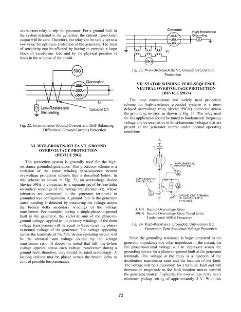
VII. STATOR WINDING ZERO-SEQUENCE<br />
NEUTRAL OVERVOLTAGE PROTECTION<br />
(DEVICE 59GN)<br />
The most conventional and widely used protection<br />
scheme for high-resistance grounded systems is a timedelayed<br />
overvoltage relay (device 59GN) connected across<br />
the grounding resistor, as shown in Fig. 24. The relay used<br />
for this application should be tuned to fundamental frequency<br />
voltage and be insensitive to third-harmonic voltages that are<br />
present at the generator neutral under normal operating<br />
conditions.<br />
VI. WYE-BROKEN-DELTA VT, GROUND<br />
OVERVOLTAGE PROTECTION<br />
(DEVICE 59G)<br />
This protection system is generally used for the highresistance<br />
grounded generators. This protection scheme is a<br />
variation of the stator winding zero-sequence neutral<br />
overvoltage protection scheme that is described below. In<br />
this scheme as shown in Fig. 23, an overvoltage device<br />
(device 59G) is connected to a separate set of broken-delta<br />
secondary windings of the voltage transformer (vt), whose<br />
primaries are connected to the generator terminals in<br />
grounded wye configuration. A ground fault in the generator<br />
stator winding is detected by measuring the voltage across<br />
the broken delta secondary windings of the voltage<br />
transformer. For example, during a single-phase-to-ground<br />
fault in the generator, the vectorial sum of the phase-toground<br />
voltages applied to the primary windings of the three<br />
voltage transformers will be equal to three times the phaseto-neutral<br />
voltage of the generator. The voltage appearing<br />
across the terminals of the 59G device operating circuit will<br />
be the vectorial sum voltage divided by the voltage<br />
transformer ratio. It should be noted that full line-to-line<br />
voltage appears across each voltage transformer during a<br />
ground fault; therefore, they should be rated accordingly. A<br />
loading resistor may be placed across the broken delta to<br />
control possible ferroresonance.<br />
51GN<br />
59GN<br />
Neutral Overvoltage Relay<br />
Neutral Overvoltage Relay Tuned to the<br />
Fundamental (60Hz) Frequency<br />
Fig. 24. High-Resistance Grounded, Unit-connected<br />
Generator, Zero-Sequence Voltage Protection<br />
Since the grounding resistance is large compared to the<br />
generator impedance and other impedance in the circuit, the<br />
full phase-to-neutral voltage will be impressed across the<br />
grounding device for a phase-to-ground fault at the generator<br />
terminals. The voltage at the relay is a function of the<br />
distribution transformer ratio and the location of the fault.<br />
The voltage will be a maximum for a terminal fault and will<br />
decrease in magnitude as the fault location moves towards<br />
the generator neutral. Typically, the overvoltage relay has a<br />
minimum pickup setting of approximately 5 V. With this<br />
73