MANUAL: Metro I & II Fixed Gallonage Nozzle - Los Angeles County ...
MANUAL: Metro I & II Fixed Gallonage Nozzle - Los Angeles County ...
MANUAL: Metro I & II Fixed Gallonage Nozzle - Los Angeles County ...

Create successful ePaper yourself
Turn your PDF publications into a flip-book with our unique Google optimized e-Paper software.
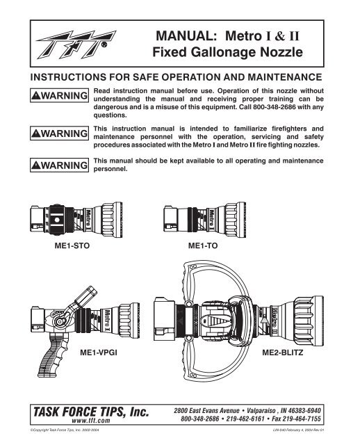
INSTRUCTIONS FOR SAFE OPERATION AND MAINTENANCE<br />
WARNING<br />
<strong>MANUAL</strong>: <strong>Metro</strong> I & <strong>II</strong><br />
<strong>Fixed</strong> <strong>Gallonage</strong> <strong>Nozzle</strong><br />
Read instruction manual before use. Operation of this nozzle without<br />
understanding the manual and receiving proper training can be<br />
dangerous and is a misuse of this equipment. Call 800-348-2686 with any<br />
questions.<br />
WARNING<br />
WARNING<br />
This instruction manual is intended to familiarize firefighters and<br />
maintenance personnel with the operation, servicing and safety<br />
procedures associated with the <strong>Metro</strong> I and <strong>Metro</strong> <strong>II</strong> fire fighting nozzles.<br />
This manual should be kept available to all operating and maintenance<br />
personnel.<br />
<strong>Metro</strong> I<br />
<strong>Metro</strong> I<br />
ME1-STO<br />
ME1-TO<br />
ME1-VPGI<br />
ME2-BLITZ<br />
TASK FORCE TIPS, Inc.<br />
www.tft.com<br />
©Copyright Task Force Tips, Inc. 2002-2004<br />
2800 East Evans Avenue • Valparaiso , IN 46383-6940<br />
800-348-2686 • 219-462-6161 • Fax 219-464-7155<br />
LIN-040 February 4, 2004 Rev 01
TABLE OF CONTENTS<br />
1.0 MEANING OF SAFETY SIGNAL WORDS<br />
2.0 GENERAL INFORMATION<br />
2.1 VARIOUS MODELS AND TERMS<br />
2.2 NOZZLE COUPLINGS<br />
3.0 FLOW CHARACTERISTICS<br />
3.1 FLOW SETTING<br />
3.2 WASHER SETTING<br />
4.0 NOZZLE CONTROLS<br />
4.1 FLOW CONTROL<br />
4.1.1 LEVER TYPE FLOW CONTROL<br />
4.1.2 TWIST SHUTOFF<br />
4.1.3 TIP ONLY NOZZLES<br />
4.2 BALL SHUTOFF<br />
4.3 PATTERN CONTROL<br />
4.4 FLUSH CONTROL<br />
4.5 USE WITH FOAM<br />
4.5.1 FOAM ASPIRATING ATTACHMENTS<br />
5.0 USE OF METRO NOZZLES<br />
6.0 FIELD INSPECTION<br />
7.0 REPAIR<br />
8.0 ANSWERS TO YOUR QUESTIONS<br />
9.0 METRO I DRAWINGS AND PARTS LIST<br />
10.0 METRO <strong>II</strong> DRAWINGS AND PARTS LIST<br />
11.0 INSPECTION CHECKLIST<br />
12.0 WARRANTY<br />
2<br />
©Copyright Task Force Tips, Inc. 2002-2004<br />
LIN-040 February 4, 2004 Rev 01
1.0 MEANING OF SAFETY SIGNAL WORDS<br />
A safety related message is identified by a safety alert symbol and a signal word to indicate the level of risk involved<br />
with a particular hazard. Per ANSI standard Z535.4-1998 the definitions of the three signal words are as follows:<br />
DANGER<br />
WARNING<br />
DANGER indicates an imminently hazardous situation which, if not avoided, will result in<br />
death or serious injury.<br />
WARNING indicates a potentially hazardous situation which, if not avoided, could result<br />
in death or serious injury.<br />
CAUTION<br />
CAUTION indicates a potentially hazardous situation which, if not avoided, may result in<br />
minor or moderate injury.<br />
2.0 GENERAL INFORMATION<br />
The Task Force Tips <strong>Metro</strong> nozzles are designed to provide excellent performance under most fire fighting conditions.<br />
Their rugged construction is compatible with the use of fresh water (see section 5.0 for saltwater use) as well as fire<br />
fighting foam solutions. Other important operating features are:<br />
- Interchangeable washer to allow for user defined flow and pressure<br />
- Quick-acting pattern control from straight stream to wide fog<br />
- "Power fog teeth" for full-fill fog<br />
- Easily flushable while flowing to clear trapped debris<br />
- TFT's five-year warranty and unsurpassed customer service<br />
WARNING<br />
WARNING<br />
WARNING<br />
This equipment is intended for use by trained personnel for firefighting. Their use for<br />
other purposes may involve hazards not addressed by this manual. Seek appropriate<br />
guidance and training to reduce risk of injury.<br />
<strong>Nozzle</strong> reaction will vary as supply conditions change: such as opening or closing other<br />
nozzles, hose line kinks, changes in pump settings, etc. Changes in spray pattern or<br />
flushing will also affect nozzle reaction. The nozzle operator must always be prepared in<br />
the event of those changes. Failure to restrain nozzle reaction can cause firefighter injury<br />
from loss of footing and/or stream protection.<br />
If nozzle gets out of control or away from operator, retreat from nozzle immediately. Do<br />
not attempt to regain control of nozzle while flowing water. Injury from whipping can<br />
occur.<br />
WARNING<br />
CAUTION<br />
Water is a conductor of electricity. Application of water solutions on high voltage<br />
equipment can cause injury or death by electrocution. The amount of current that may be<br />
carried back to the nozzle will depend on the following factors:<br />
Voltage of the line or equipment<br />
Distance from the nozzle to the line or equipment<br />
Size of the stream<br />
Whether the stream is solid or broken<br />
1<br />
Purity of the water<br />
1 The Fire Fighter and Electrical Equipment,<br />
The University of Michigan Extension<br />
Service, Fourth Printing 1983. Page 47.<br />
Fire streams are capable of injury and damage. Do not direct water stream to cause injury<br />
or damage to persons or property.<br />
©Copyright Task Force Tips, Inc. 2002-2004<br />
3<br />
LIN-040 February 4, 2004 Rev 01
2.1 VARIOUS MODELS AND TERMS<br />
<strong>Fixed</strong> Flow: A nozzle with a discharge orifice that is a fixed opening size.<br />
Tip Only: a nozzle without an integral ball shutoff valve. A <strong>Metro</strong> tip only nozzle is available in a variety of flow<br />
ranges and configurations. All models deliver the rated flow when the rated pressure is supplied to the nozzle.<br />
SERIES RECOMMENDED FLOW SETTINGS NOZZLE TYPE<br />
HOSE SIZE (INCHES)<br />
METRO I 1-1/2 Field Changeable <strong>Fixed</strong> Flow<br />
(small body)<br />
To Any of 10 Sizes<br />
METRO <strong>II</strong> 1-1/2 to 2-1/2 Field Changeable <strong>Fixed</strong> Flow<br />
(large body)<br />
To Any of 8 Sizes<br />
DETENTS<br />
COUPLING<br />
ON<br />
FLOW CONTROL<br />
OFF<br />
STREAM<br />
SHAPER<br />
NAME LABEL<br />
BARREL<br />
LABEL<br />
FLOW<br />
CONTROL<br />
WASHER<br />
RUBBER<br />
GASKET<br />
PISTOL<br />
GRIP<br />
NOZZLE WITH VALVE<br />
and INTEGRAL PISTOL GRIP<br />
TIP ONLY NOZZLE<br />
VALVE POSITION<br />
LABEL<br />
VALVE RING<br />
FIGURE 1 COMMON MODEL AND TERMS<br />
TIP ONLY NOZZLE<br />
WITH TWIST SHUTOFF<br />
2.2 NOZZLE COUPLING<br />
NH (National Hose Threads per NFPA #1963) threads are standard on all nozzles. Other threads such as NPSH (National<br />
Pipe Straight Hose threads per ANSI/ASME #B1.20.7) can be specified at time of order.<br />
CAUTION<br />
<strong>Nozzle</strong> must be properly connected. Mismatched or damaged threads may cause nozzle<br />
to leak or uncouple under pressure and could cause injury.<br />
4<br />
CAUTION<br />
©Copyright Task Force Tips, Inc. 2002-2004<br />
Dissimilar metals coupled together can cause galvanic corrosion that can result<br />
in the inability to unscrew the threads of complete loss of thread engagement<br />
over time. Per NFPA 1962 (1998 edition), if dissimilar metals are left coupled<br />
together an anti-corrosive lubricant should be applied to the threads. Also the<br />
coupling should be disconnected and inspected at least quarterly.<br />
LIN-040 February 4, 2004 Rev 01
3.0 FLOW CHARACTERISTICS<br />
The opening size of the <strong>Metro</strong> nozzles may be field set to any one of the several different sizes. At each flow setting the<br />
nozzle is set to a predetermined fixed orifice. Relationship of flow and nozzle pressure at each setting is shown below.<br />
PRESSURE (PSI)<br />
150<br />
140<br />
130<br />
120<br />
110<br />
100<br />
90<br />
80<br />
70<br />
60<br />
50<br />
40<br />
METRO I FLOW CHART<br />
FLOW (L/min)<br />
190 380 550 750 950 1140<br />
10.34 bar<br />
<br />
95 GPM @ 100 PSI (K=9.5)<br />
125 GPM @ 100 PSI (K=12.5)<br />
125 GPM @ 75 PSI (K=14.4)<br />
150 GPM @ 100 PSI (K=15.0)<br />
150 GPM @ 75 PSI (K=17.3)<br />
175 GPM @ 100 PSI (K=17.5)<br />
30<br />
200 GPM @ 100 PSI (K=20.0) 2.07 bar<br />
20<br />
175 GPM @ 75 PSI (K=20.2)<br />
1.38 bar<br />
150 GPM @ 50PSI (K=21.2)<br />
10<br />
0.69 bar<br />
200 GPM @ 75 PSI (K=23.1)<br />
0<br />
0 50 100 150 200 250 300<br />
FLOW (GPM)<br />
<br />
<br />
<br />
<br />
<br />
<br />
<br />
9.65 bar<br />
8.96 bar<br />
8.27 bar<br />
7.58 bar<br />
6.90 bar<br />
6.20 bar<br />
5.52 bar<br />
4.83 bar<br />
4.12 bar<br />
3.45 bar<br />
2.76 bar<br />
REACTION FORCE (LBF)<br />
200<br />
180<br />
160<br />
140<br />
120<br />
100<br />
80<br />
60<br />
40<br />
20<br />
METRO I FLOW VS REACTION FORCE<br />
FLOW (L/min)<br />
190 380 550 750 950 1140<br />
90.7 kgf<br />
<br />
<br />
200 GPM @ 75 PSI (K=23.1)<br />
0<br />
0 50 100 150 200 250 300<br />
<br />
FLOW (GPM)<br />
<br />
<br />
<br />
<br />
<br />
<br />
<br />
<br />
<br />
<br />
<br />
<br />
<br />
<br />
<br />
<br />
<br />
95 GPM @ 100 PSI (K=9.5)<br />
125 GPM @ 100 PSI (K=12.5)<br />
125 GPM @ 75 PSI (K=14.4)<br />
150 GPM @ 100 PSI (K=15.0)<br />
150 GPM @ 75 PSI (K=17.3)<br />
175 GPM @ 100 PSI (K=17.5)<br />
200 GPM @ 100 PSI (K=20.0)<br />
175 GPM @ 75 PSI (K=20.2)<br />
150 GPM @ 50 PSI (K=21.2)<br />
68.0 kgf<br />
45.4 kgf<br />
22.7 kgf<br />
©Copyright Task Force Tips, Inc. 2002-2004<br />
5<br />
LIN-040 February 4, 2004 Rev 01
3.0 FLOW CHARACTERISTICS (continued)<br />
150<br />
METRO <strong>II</strong> FLOW CHART<br />
FLOW (L/min)<br />
190 380 550 750 950 1140 1325 1525 1700<br />
10.34 bar<br />
140<br />
9.65 bar<br />
130<br />
8.96 bar<br />
120<br />
8.27 bar<br />
110<br />
7.58 bar<br />
100<br />
6.90 bar<br />
PRESSURE (PSI)<br />
90<br />
80<br />
70<br />
60<br />
50<br />
40<br />
30<br />
20<br />
10<br />
125 GPM @ 75 PSI (K=14.4)<br />
175 GPM @ 100 PSI (K=17.5)<br />
185 GPM @ 75 PSI (K=21.4)<br />
200 GPM @ 75 PSI (K=23.1)<br />
250 GPM @ 100 PSI (K=25.0)<br />
250 GPM @ 75 PSI (K=28.9)<br />
325 GPM @ 100 PSI (K=32.5)<br />
250 GPM @ 50 PSI (K=35.4)<br />
6.20 bar<br />
5.52 bar<br />
4.83 bar<br />
4.12 bar<br />
3.45 bar<br />
2.76 bar<br />
2.07 bar<br />
1.38 bar<br />
0.69 bar<br />
0<br />
0 50 100 150 200 250 300 350 400 450<br />
FLOW (GPM)<br />
METRO <strong>II</strong> FLOW VS. REACTION FORCE<br />
FLOW (L/min)<br />
300<br />
190 380 550 750 950 1140 1325 1525 1700<br />
136.1 kgf<br />
250<br />
113.4 kgf<br />
REACTION FORCE (LBF)<br />
200<br />
150<br />
100<br />
50<br />
125 GPM @ 75 PSI (K=14.4)<br />
175 GPM @ 100 PSI (K=17.5)<br />
185 GPM @ 75 PSI (K=21.4)<br />
200 GPM @ 75 PSI (K=23.1)<br />
250 GPM @ 100 PSI (K=25.0)<br />
250 GPM @ 75 PSI (K=28.9)<br />
325 GPM @ 100 PSI (K=32.5)<br />
250 GPM @ 50 PSI (K=35.4)<br />
90.7 kgf<br />
68.0 kgf<br />
45.4 kgf<br />
22.7 kgf<br />
0<br />
0 50 100 150 200 250 300 350 400 450<br />
FLOW (GPM)<br />
6<br />
©Copyright Task Force Tips, Inc. 2002-2004<br />
LIN-040 February 4, 2004 Rev 01
3.1 FLOW SETTING<br />
The washers are marked with various flow settings. Change washer to the desired setting. The nozzle will flow the<br />
indicated amount when the pressure at the nozzle is at the indicated level.<br />
3.2 WASHER SETTING<br />
To change flow and pressure setting of the <strong>Metro</strong>,<br />
use the following instructions:<br />
1) Set nozzle into FLUSH.<br />
2) Push baffle down to barrel cone.<br />
3) Remove screw and washer using a 5/32 hex key.<br />
4) Remove pre-set flow washer and slide desired<br />
flow washer onto shaft, markings facing up.<br />
5) Thread screw with washer back into shaft until<br />
snug (Do not over tighten).<br />
FLOW WASHER<br />
HM410-** METRO I<br />
HX410-** METRO <strong>II</strong><br />
WASHER<br />
VW687X281-50<br />
METRO I & <strong>II</strong><br />
SCREW<br />
VT25Y28BH500<br />
METRO I & <strong>II</strong><br />
SHAFT<br />
HM470 - METRO I<br />
HX470 - METRO <strong>II</strong><br />
BAFFLE<br />
HM461 - METRO I<br />
HX461 - METRO <strong>II</strong><br />
DANGER<br />
WARNING<br />
WARNING<br />
WARNING<br />
CAUTION<br />
An inadequate supply of nozzle pressure and/or flow will cause an ineffective stream and<br />
can result in injury, death or loss of property. See flow charts in section 3.0 or call 800-<br />
348-2686 for assistance.<br />
Failure to secure screw and washer will result in the baffle becoming loose. This will<br />
produce poor stream, improper flows and possible discharge of the complete baffle.<br />
Failure to restrain nozzle reaction can cause firefighter injury from loss of footing and/or<br />
stream protection. <strong>Nozzle</strong> reaction will vary as supply conditions change: such as<br />
opening or closing other nozzles, hose line kinks, changes in pump settings, etc.<br />
Changes in spray pattern or flushing will also affect nozzle reaction. The nozzle operator<br />
must always be positioned to restrain the nozzle reaction in the event of those changes.<br />
Injury from whipping can occur. If nozzle gets out of control or away from operator, retreat<br />
from nozzle immediately. Do not attempt to regain control of nozzle while flowing water.<br />
Fire streams are capable of injury and damage. Do not direct water stream to cause injury<br />
or damage to persons or property.<br />
4.0 NOZZLE CONTROLS<br />
4.1 FLOW CONTROL<br />
4.1.1 LEVER TYPE FLOW CONTROL<br />
On models that use a lever type valve handle, the nozzle is shut<br />
off when the handle is fully forward. The valve handle has six<br />
detent flow positions. These detent positions allow the nozzle<br />
operator to regulate the flow of the nozzle depending on the<br />
need or what can be safely and effectively handled. TFT<br />
recommends the use of a pistol grip for easier handling. For<br />
additional stress reduction, a hose rope or strap may also be<br />
used. This permits more effective use and ease of<br />
advancement, while minimizing strain and fatigue.<br />
©Copyright Task Force Tips, Inc. 2002-2004<br />
FLOW CONTROL<br />
ON<br />
OFF<br />
7<br />
LIN-040 February 4, 2004 Rev 01
4.1.2 TWIST SHUTTOFF<br />
On models that use a twist flow control, the valve is opened or closed by rotating the valve ring. Rotating the ring<br />
clockwise (as seen from the operating position behind the nozzle) closes the valve, while counterclockwise rotation<br />
opens it. Detents are provided at four intermediate positions and the position of the valve is shown by the exposed valve<br />
position label.<br />
VALVE POSITION<br />
LABEL<br />
VALVE RING<br />
FLOW PATTERN<br />
LABEL<br />
4.1.3 TIP ONLY NOZZLES<br />
Tip only nozzles have NO shut off valve contained within the nozzle and MUST be used with a separate ball valve<br />
attached to the nozzle.<br />
<strong>Metro</strong> <strong>II</strong><br />
4.2 BALL VALVE SHUTOFF<br />
Models with a ball valve are shut off when the valve handle is fully forward. Pulling<br />
back on the handle opens the valve. Open valve slowly to avoid sudden changes in<br />
nozzle reaction. Close valve slowly to prevent water hammer. Note: In partially open<br />
positions a ball valve will cause turbulence and adversely affect stream quality.<br />
FLOW CONTROL<br />
ON<br />
OFF<br />
FLOW CONTROL<br />
ON<br />
OFF<br />
8<br />
©Copyright Task Force Tips, Inc. 2002-2004<br />
LIN-040 February 4, 2004 Rev 01
4.3 PATTERN CONTROL<br />
TFT's <strong>Metro</strong> has full pattern control from straight stream to wide fog. Turning the STREAM SHAPER clockwise (as seen<br />
from the operating position behind the nozzle) moves the SHAPER to the straight stream position. Turning the SHAPER<br />
counterclockwise will result in an increasingly wider pattern.<br />
Since the stream trim point varies with the flow, the stream should be "trimmed" after changing the flow to obtain the<br />
straightest and farthest reaching stream. To properly trim a stream, first open the pattern to a narrow fog. Then close the<br />
stream to parallel to give maximum reach. NOTE: Turning the shaper further forward will cause stream crossover<br />
and reduce the effective reach of the nozzle.<br />
The nozzle reaction is greatest when the shaper is in the straight stream position. The nozzle operator must be prepared<br />
for a change in reaction as the pattern is changed.<br />
4.4 FLUSH CONTROL<br />
Small debris may get caught inside the nozzle. This trapped material will cause poor stream quality, shortened reach and<br />
reduced flow. To remove this trapped debris the nozzle can be flushed as follows; while still flowing water, turn the<br />
SHAPER counterclockwise past the full fog position (increased resistance will be felt on the SHAPER as the nozzle goes<br />
into flush). This will open the nozzle allowing debris to pass through. Rotate the SHAPER clockwise and out of flush to<br />
continue normal operation. During flush the nozzle reaction will decrease as the pattern becomes wider and the pressure<br />
drops. The nozzle operator must be prepared for an increase of nozzle reaction when returning the nozzle from the flush<br />
position to retain control of the nozzle.<br />
WARNING<br />
Large amounts or pieces of debris may be unflushable and can reduce the flow of the<br />
nozzle resulting in an ineffective flow. In the event of a blockage, it may be necessary<br />
to retreat to a safe area, uncouple nozzle and remove debris.<br />
4.5 USE WITH FOAM<br />
The <strong>Metro</strong> nozzles may be used with foam solutions. Refer to fire service training for the proper use of foam.<br />
WARNING<br />
WARNING<br />
WARNING<br />
For Class B fires, lack of foam or interruption in the foam stream can cause a break in the<br />
foam blanket and greatly increase the risk of injury or death. Assure that:<br />
Application rate is sufficient (see NFPA 11 or foam manufacturer's<br />
recommendations).<br />
Enough concentrate is on hand to complete task (see NFPA for minimum duration<br />
time requirements).<br />
Foam logistics have been carefully planned. Allow for such things as:<br />
Storage of foam in a location not exposed to the hazard it protects.<br />
Personnel, equipment and technique to deliver foam at a rapid enough rate.<br />
Removal of empty foam containers.<br />
Clear path to deliver foam, as hoses and other equipment and vehicles are<br />
deployed.<br />
Improper use of foam can result in injury or damage to the environment. Follow foam<br />
manufacturer's instructions and fire service training to avoid:<br />
Using wrong type of foam on a fire, i.e. Class A foam on a Class B fire.<br />
Plunging foam into pools of burning liquid fuels.<br />
Causing environmental damage.<br />
Directing stream at personnel.<br />
There is a wide variety of foam concentrates. Each user is responsible for verifying that<br />
any foam concentrate chosen to be used with this unit has been tested to assure that the<br />
foam obtained is suitable for the purpose intended.<br />
©Copyright Task Force Tips, Inc. 2002-2004<br />
9<br />
LIN-040 February 4, 2004 Rev 01
4.5.1 FOAM ASPIRATING ATTACHMENTS<br />
To increase the expansion ratio, Task Force Tips "MX Foamjet" (model FJ-MX-HM) multi expansion attachment or LX<br />
Foamjet (model FJ-LX-HM) low expansion attachment may be used with the <strong>Metro</strong> I nozzle and (model FJ-HMX) multi<br />
expansion attachment or LX Foamjet (model FJ-H) low expansion attachment may be used with the <strong>Metro</strong> <strong>II</strong> nozzle.<br />
These foam tubes attach and detach quickly from the nozzle. Note: As expansion ratio is increased, the reach of the<br />
nozzle will be decreased due to the greater amount of bubbles in the stream and their inability to penetrate the air.<br />
Generally the reach with foam is approximately 10% less than with water only. Actual results will vary based on brand of<br />
foam, hardness of water, temperature, etc. See Foamjet instruction manual for specific information.<br />
METRO I<br />
METRO <strong>II</strong><br />
FJ-MX-HM - Multi Expansion<br />
Foam Attachment<br />
FJ-HMX - Multi Expansion<br />
Foam Attachment<br />
FJ-LX-HM - Low Expansion<br />
Foam Attachment<br />
FJ-H - Low Expansion<br />
Foam Attachment<br />
5.0 USE OF METRO NOZZLES<br />
IT IS THE RESPONSIBILITY OF THE INDIVIDUAL FIRE DEPARTMENT OR AGENCY TO DETERMINE PHYSICAL<br />
CAPABILITIES AND SUITABILITY FOR AN INDIVIDUAL'S USE OF THIS EQUIPMENT.<br />
Many factors contribute to the extinguishment of a fire. Among the most important is delivering water at a flow rate<br />
sufficient to absorb heat faster than it is being generated. The flow rate depends largely on the pump discharge pressure<br />
and hose friction loss. It can be calculated using a hydraulic equation such as:<br />
PDP = NP+FL+DL+EL<br />
For additional information on calculating specific hose<br />
layouts, consult an appropriate fire service training manual,<br />
such as IFSTA, or A Guide to Automatic <strong>Nozzle</strong>s, or call TFT's<br />
"Hydraulics Hotline" at 800-348-2686.<br />
PDP = Pump discharge pressure in PSI<br />
NP = <strong>Nozzle</strong> pressure in PSI<br />
FL = Hose friction loss in PSI<br />
DL = Device loss in PSI<br />
EL = Elevation loss in PSI<br />
10<br />
©Copyright Task Force Tips, Inc. 2002-2004<br />
LIN-040 February 4, 2004 Rev 01
6.0 FIELD INSPECTION<br />
TFT's <strong>Metro</strong> is designed and manufactured to be damage resistant and require minimal maintenance. However, as the<br />
primary fire fighting tools upon which your life depends, they should be treated accordingly.<br />
Use with saltwater is permissible provided nozzle is thoroughly cleaned with fresh water after each use. The service life of<br />
the nozzle may be shortened due to the effects of corrosion and is not covered under warranty.<br />
WARNING<br />
<strong>Nozzle</strong> must be inspected for proper operation and function according to inspection<br />
checklist on last page before each use. Any nozzle that fails inspection is dangerous to<br />
use and must be repaired before using.<br />
Performance tests shall be conducted on the <strong>Metro</strong> nozzle after a repair, or anytime a problem is reported to verify<br />
operation in accordance with TFT test procedures. Consult factory for the procedure that corresponds to the model and<br />
serial number of the nozzle. Any equipment which fails the related test criteria should be removed from service<br />
immediately. Troubleshooting guides are available with each test procedure or equipment can be returned to the factory<br />
for service and testing.<br />
Factory service is available with repair time seldom exceeding one day in our facility. Factory serviced nozzles are<br />
repaired by experienced technicians to original specifications, fully tested and promptly returned. Any returns should<br />
include a note as to the nature of the problem, who to reach in case of questions and if a repair estimate is required.<br />
CAUTION<br />
Any alterations to the nozzle and its markings could diminish safety and constitutes a<br />
misuse of this product.<br />
All Task Force Tip nozzles are factory lubricated with high quality silicone grease. This lubricant has excellent washout<br />
resistance and long term performance. If your department has unusually hard or sandy water, the moving parts may be<br />
affected. Foam agents and water additives contain soaps and chemicals that may break down the factory lubrication.<br />
The moving parts of the nozzle should be checked on a regular basis for smooth and free operation, and signs of<br />
damage. IF THE NOZZLE IS OPERATING CORRECTLY, THEN NO ADDITIONAL LUBRICATION IS NEEDED. Any<br />
nozzle that is not operating correctly should be immediately removed from service and the problem corrected.<br />
7.0 REPAIR<br />
Factory service is available with repair time seldom exceeding one day in our facility. Factory-serviced nozzles are<br />
repaired by experienced technicians to original specifications, fully wet tested, and promptly returned. Repair charges for<br />
non-warranty items are minimal. Any returns should include a note as to the nature of the problem and whom to reach in<br />
case of questions.<br />
Task Force Tips assumes no liability for damage to equipment or injury to personnel that is a result of user service.<br />
Repair kits and repair parts are stocked for immediate shipment. Contact the factory or visit the website at www.tft.com for<br />
parts lists, exploded views, test procedures and trouble shooting guides.<br />
8.0 ANSWERS TO YOUR QUESTIONS<br />
We appreciate the opportunity of serving you and making your job easier. If you have any problems or questions, our tollfree<br />
"Hydraulics Hotline", 800-348-2686, is normally available to you 24 hours a day, 7 days a week.<br />
©Copyright Task Force Tips, Inc. 2002-2004<br />
11<br />
LIN-040 February 4, 2004 Rev 01
10.0 METRO I DRAWINGS &<br />
PART LIST<br />
BACK END<br />
PARTS<br />
FRONT END PARTS<br />
12<br />
©Copyright Task Force Tips, Inc. 2002-2004<br />
LIN-040 February 4, 2004 Rev 01
METRO I - SERVICE PROCEDURE PARTS LIST<br />
DESCRIPTION QTY ORDER #<br />
1 1.5" COUPLING GASKET 1 V3130<br />
2 1.5" ROCKER LUG COUPLING 1 HM697*<br />
5 3/16 SS BALLS 33 V2120<br />
7 ¼-28 X 3/8 SOCKET SET SCREW 1 VT25-28SS375<br />
8 GASKET GRABBER 1 HM730<br />
9 O-RING-134 1 VO-134<br />
10 VALVE BODY<br />
VALVE DISK<br />
DRAG NUB<br />
SMALLEY RING<br />
* Specify Thread<br />
1<br />
2<br />
4<br />
2<br />
HM600<br />
HM640<br />
HM650<br />
V4270<br />
11 VALVE HANDLE 1 HM620<br />
12 DETENT SPRING 2 HM770<br />
13 DETENT BALL 2 VB243TO<br />
14 HANDLE SCREW 2 HM645<br />
15 CAM PIN 1 HM630<br />
16 SAFETY PIN 1 HM635<br />
17 VALVE HANDLE COVER 2 HM625-BLK<br />
18 8-32 x 3/8 BUTTON HEAD CAP SCREW 4 HM626<br />
19 10-32 x 3/16 SOCKET SET SCREW 2 VT10Y32SS187<br />
20 QUADX-4221 1 VOQ-4221<br />
21 QUADX-4130 1 VOQ-4130<br />
22 SLIDER 1 HM660<br />
23 VALVE PLUG 1 HM590<br />
26 S.T.O. TAIL PIECE 1 HM662<br />
27 O-RING-129 1 VO-129<br />
28 O-RING-138 1 VO-138<br />
29 S.T.O. SLIDER 1 HM661<br />
30 QUADX-4037 2 VOQ-4037<br />
31 "OFF" LABEL 1 HD755<br />
32 "ON" LABEL 1 HD750<br />
33 S.T.O. BASE 1 HM655<br />
34 DETENT SPRING 2 VM4200<br />
35 3/16" TORLON BALLS 2 V2120-TORLON<br />
36 S.T.O. SLEEVE 1 HM668<br />
37 DETENT SCREW 2 HD785<br />
38 CAM SCREW 2 HD780<br />
39 S.T.O. VALVE PLUG 1 HM592<br />
40 T.O. BASE 1 HM670<br />
41 T.O. VALVE PLUG 1 HM591<br />
46 O-RING-139 1 VO-139<br />
47 SHAPER GUIDE 1 HM510<br />
48 NAME LABEL 1 HM745-RED<br />
52 TORLON GUIDE BALLS 3 VB243TO<br />
53 FIN CAN/BARREL 1 HM545<br />
55 BARREL LABEL 1 HM740-RED<br />
57 O-RING-030 1 VO-030<br />
58 WS-175-S02 SMALLEY RING 1 VR4230<br />
59 FLUSH WAVE SPRING 1 HM785<br />
60 BARREL CONE 1 HM520<br />
61 1/8 NYLON BALL 64 V2135<br />
62 O-RING-230 1 VO-230<br />
63 SHAPER WITH BUMPER 1 HM500<br />
64 ¼-28 X ¾ SH CAP SCREW 1 VT25-28SH750<br />
65 LOCKING SLEEVE 1 HM571<br />
66 SHAFT 1 HM470<br />
67 O-RING 011 1 VO-011<br />
68 BAFFLE 1 HM461<br />
69 FLOW WASHER K=12.5 OR 9.5<br />
FLOW WASHER K=15.0 OR 14.4<br />
FLOW WASHER K=17.5 OR 17.3<br />
FLOW WASHER K-20.0 OR 20.2<br />
FLOW WASHER K=23.1 OR 21.2<br />
1 HM410-14<br />
HM410-15<br />
HM410-17<br />
HM410-21<br />
HM410-23<br />
70 FLAT WASHER 1 VW687X281-50<br />
71 ¼-28 X ½ BUTTON HEAD 1 VT25Y28BH500<br />
80 PISTOL GRIP 1 HM692-BLK<br />
81 SPACER 1 HM693-HM<br />
82 WASHER 1 VM4901<br />
83 3/8-16 X 1 SOCKET HEAD CAP SCREW 1 VT37-16SH1.0<br />
©Copyright Task Force Tips, Inc. 2002-2004<br />
13<br />
LIN-040 February 4, 2004 Rev 01
11.0 METRO <strong>II</strong> DRAWINGS &<br />
PART LIST<br />
BACK END<br />
PARTS<br />
COUPLINGS<br />
VALVE PARTS<br />
FRONT END PARTS<br />
SPRAY ADJUSTMENT PARTS<br />
14<br />
©Copyright Task Force Tips, Inc. 2002-2004<br />
LIN-040 February 4, 2004 Rev 01
©Copyright Task Force Tips, Inc. 2002-2004<br />
METRO <strong>II</strong>- SERVICE PROCEDURE PARTS LIST<br />
INDEX DESCIRPTION QTY PART NUMBER<br />
1 CAP NUT 1 H420<br />
2 GASKET - 2.5" HOSE COUPLING 1 V3190<br />
3 COUPLING 2.5" NH ROCKERLUG 1 P198N (P198I - NPSH)<br />
4 3/16" BALL - 302 STAINLESS 37 V2120<br />
5 1/4-28 X 3/16 SOCKET SET SCREW<br />
¼-28 X 3/8 SOCKET SET SCREW<br />
1 VT25-28SS187 (SWIVEL)<br />
VT25-28SS375 (LOCK-OUT)<br />
6 O-RING-141 2-5/16 ID 3/32 C/S 1 VO-141<br />
7 ANTI GG RING 2 P147<br />
8 BARREL LABEL – RED 1 H740-RED<br />
10 BARREL 1 HX440<br />
11 O-RING-033 1 VO-033<br />
16 BARREL CONE 1 HX520<br />
17 METRO <strong>II</strong> NAME LABEL 1 H745-RED<br />
18 SHAPER GUIDE 1 HX510<br />
19 O-RING-336 2-7/8 ID 3/16 C/S 1 VO-336<br />
20 3/16" BALL – ACETAL 48 V2115<br />
21 SHAPER WITH BUMPER 1 H500<br />
22 SHAFT 1 HX470<br />
23 O-RING-011 5/16 ID 1/16 C/S 1 VO-011<br />
24 BAFFLE 1 H461<br />
25 FLOW WASHER<br />
FLOW WASHER K=17.0 OR K=14.4<br />
FLOW WASHER K=23.1 OR K=21.3<br />
FLOW WASHER K=28.9 OR K=25.0<br />
FLOW WASHER K=35.4 OR K=32.5<br />
1<br />
1<br />
1<br />
1<br />
HX410-16<br />
HX410-22<br />
HX410-26<br />
HX410-34<br />
27 FLAT WASHER 1 VW687X281-50<br />
28 ¼-28 BUTTON HEAD SCREW 1 VT25Y28BH500<br />
29 SMALLEY RING 1 VR4270<br />
30 WAVE SPRING 1 HX785<br />
31 2.5” ROCKERLUG COUPLING 1 P197<br />
32 O-RING –151 1 VO-151<br />
33 ¼-28 X ¼ SET SCREW 1 VT25-28SS250<br />
34 1/4-28 X 3/8 SOCKET SET SCREW 1 VT25-28SS375<br />
35 3/16 SS BALL 38 V2120<br />
36 2.5” BLITZ BASE 1 H675<br />
38 ¼-20 ACORN NUT – STAINLESS 8 VT25E20AC<br />
39 ¼-20 X 2” STUD – STAINLESS 4 VT25-20ST2.0<br />
40 ¼ WASHER 8 VW500X265-63<br />
41 BLITZ BRACKET 4 H676<br />
42 PLAYPIPE HANDLE 2 P220<br />
43 1.5” GASKET 1 V3130<br />
44 1.5” ROCKERLUG COUPLING 1 H694<br />
45 SAFETY PIN 1 HX635<br />
46 VALVE HANDLE 1 HX620<br />
47 CAM PIN 1 HX630<br />
48 HANDLE SCREW 2 VT37E24BH750<br />
49 BLACK HANDLE COVER 2 HM625-BLK<br />
50 8-32 X 3/8 BUTTON HEAD 4 HM626-1<br />
51 BALL .243” - TORLON 2 VB243TO<br />
52 DETENT SPRING 2 HM770<br />
53 DETENT VALVE BODY<br />
BLUE VALVE LABEL<br />
1<br />
1<br />
P110<br />
H750<br />
54 BALL VALVE SEAT 2 P104<br />
55 BALL VALVE 1 P103<br />
56 O-RING –227 1 VO-227<br />
57 PLAYPIPE ADAPTER 1 HX450<br />
58 GRIP SPACER 1 HM693-H<br />
59 PISTOL GRIP 1 HM692-BLK<br />
60 FLAT WASHER 1 VM4901<br />
61 3/8-16 X 1 SOCKET HEAD CAP 1 VT37-16SH1.0<br />
62 3/8-24 X 3/8 SOCKET SET SCREW 1 VT37-24SS375<br />
63 BALL .344” – TORLON 3 VB344TO<br />
64 10-32 x 3/16 SOCKET SET SCREW 2 VT10Y32SS187<br />
65 3/16 X 9/16 HDP SPIROL 2 V2005<br />
66 TRUNNION DRIVER 2 HX650<br />
67 TRUNNION – LEFT<br />
TRUNNION – RIGHT<br />
1<br />
1<br />
P120L<br />
P120R<br />
68 TRUNNION SHIM 2 P170<br />
69 O-RING –118 2 VO-118<br />
* Specify Thread 15<br />
LIN-040 February 4, 2004 Rev 01
12.0 INSPECTION CHECKLIST<br />
<strong>Nozzle</strong> must be inspected before each use for proper operation and function according<br />
to this checklist. Check that:<br />
1) There is no obvious damage such as missing, broken or loose parts, damaged labels, etc.<br />
2) Coupling is tight and leak free<br />
3) Valve handle moves freely though full range and shuts off flow<br />
4) <strong>Nozzle</strong> flow is adequate as indicated by pump pressure and nozzle reaction<br />
5) Shaper turns freely and adjusts pattern through full range<br />
6) <strong>Nozzle</strong> moves smoothly in and out of flush position<br />
WARNING<br />
Any nozzle failing any part of the inspection checklist is unsafe and must have the<br />
problem corrected before use. Operating a nozzle that fails any of the above inspections<br />
is a misuse of this equipment.<br />
13.0 WARRANTY<br />
Task Force Tips, Inc., 2800 East Evans Avenue, Valparaiso, Indiana 46383-6940 ("TFT") warrants to the original purchaser<br />
of its <strong>Metro</strong> series nozzles ("equipment"), and to anyone to whom it is transferred, that the equipment shall be free from<br />
defects in material and workmanship during the five (5) year period from the date of purchase.<br />
TFT's obligation under this warranty is specifically limited to replacing or repairing the equipment (or its parts) which are<br />
shown by TFT's examination to be in a defective condition attributable to TFT. To qualify for this limited warranty, the<br />
claimant must return the equipment to TFT, at 2800 East Evans Avenue, Valparaiso, Indiana 46383-6940, within a<br />
reasonable time after discovery of the defect. TFT will examine the equipment. If TFT determines that there is a defect<br />
attributable to it, TFT will correct the problem within a reasonable time. If the equipment is covered by this limited<br />
warranty, TFT will assume the expenses of repair.<br />
If any defect attributable to TFT under this limited warranty cannot be reasonably cured by repair or replacement, TFT<br />
may elect to refund the purchase price of the equipment, less reasonable depreciation, in complete discharge of its<br />
obligations under this limited warranty. If TFT makes this election, claimant shall return the equipment to TFT free and<br />
clear of any liens and encumbrances.<br />
This is a limited warranty. The original purchaser of the equipment, any person to whom it is transferred, and any person<br />
who is an intended or unintended beneficiary of the equipment, shall not be entitled to recover from TFT any<br />
consequential or incidental damages for injury to person and/or property resulting from any defective equipment<br />
manufactured or assembled by TFT. It is agreed and understood that the price stated for the equipment is in part<br />
consideration for limiting TFT's liability. Some states do not allow the exclusion or limitation of incidental or consequential<br />
damages, so the above may not apply to you.<br />
TFT shall have no obligation under this limited warranty if the equipment is, or has been, misused or neglected (including<br />
failure to provide reasonable maintenance) or if there have been accidents to the equipment or if it has been repaired or<br />
altered by someone else.<br />
THIS IS A LIMITED EXPRESS WARRANTY ONLY. TFT EXPRESSLY DISCLAIMS WITH RESPECT TO THE<br />
EQUIPMENT ALL IMPLIED WARRANTIES OF MERCHANTABILITY AND ALL IMPLIED WARRANTIES OF FITNESS<br />
FOR A PARTICULAR PURPOSE. THERE IS NO WARRANTY OF ANY NATURE MADE BY TFT BEYOND THAT<br />
STATED IN THIS DOCUMENT.<br />
This limited warranty gives you specific legal rights, and you may also have other rights which vary from state to state.<br />
TASK FORCE TIPS, Inc.<br />
www.tft.com<br />
©Copyright Task Force Tips, Inc. 2002-2004<br />
2800 East Evans Avenue • Valparaiso , IN 46383-6940<br />
800-348-2686 • 219-462-6161 • Fax 219-464-7155<br />
LIN-040 February 4, 2004 Rev 01