CLC fa2005.pdf - Odeon
CLC fa2005.pdf - Odeon
CLC fa2005.pdf - Odeon

Create successful ePaper yourself
Turn your PDF publications into a flip-book with our unique Google optimized e-Paper software.
Forum Acusticum 2005 Budapest<br />
Christensen, Rindel<br />
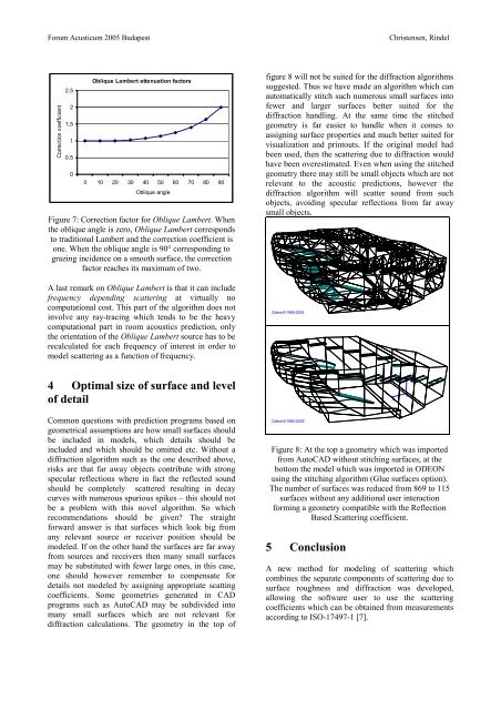
Correction coefficient<br />
2,5<br />
2<br />
1,5<br />
1<br />
0,5<br />
0<br />
Oblique Lambert attenuation factors<br />
0 10 20 30 40 50 60 70 80 90<br />
Oblique angle<br />
Figure 7: Correction factor for Oblique Lambert. When<br />
the oblique angle is zero, Oblique Lambert corresponds<br />
to traditional Lambert and the correction coefficient is<br />
one. When the oblique angle is 90° corresponding to<br />
grazing incidence on a smooth surface, the correction<br />
factor reaches its maximum of two.<br />
figure 8 will not be suited for the diffraction algorithms<br />
suggested. Thus we have made an algorithm which can<br />
automatically stitch such numerous small surfaces into<br />
fewer and larger surfaces better suited for the<br />
diffraction handling. At the same time the stitched<br />
geometry is far easier to handle when it comes to<br />
assigning surface properties and much better suited for<br />
visualization and printouts. If the original model had<br />
been used, then the scattering due to diffraction would<br />
have been overestimated. Even when using the stitched<br />
geometry there may still be small objects which are not<br />
relevant to the acoustic predictions, however the<br />
diffraction algorithm will scatter sound from such<br />
objects, avoiding specular reflections from far away<br />
small objects.<br />
Z<br />
A last remark on Oblique Lambert is that it can include<br />
frequency depending scattering at virtually no<br />
computational cost. This part of the algorithm does not<br />
involve any ray-tracing which tends to be the heavy<br />
computational part in room acoustics prediction, only<br />
the orientation of the Oblique Lambert source has to be<br />
recalculated for each frequency of interest in order to<br />
model scattering as a function of frequency.<br />
<strong>Odeon</strong>©1985-2005<br />
X<br />
O<br />
Y<br />
4 Optimal size of surface and level<br />
of detail<br />
X<br />
Z<br />
O<br />
Y<br />
Common questions with prediction programs based on<br />
geometrical assumptions are how small surfaces should<br />
be included in models, which details should be<br />
included and which should be omitted etc. Without a<br />
diffraction algorithm such as the one described above,<br />
risks are that far away objects contribute with strong<br />
specular reflections where in fact the reflected sound<br />
should be completely scattered resulting in decay<br />
curves with numerous spurious spikes – this should not<br />
be a problem with this novel algorithm. So which<br />
recommendations should be given? The straight<br />
forward answer is that surfaces which look big from<br />
any relevant source or receiver position should be<br />
modeled. If on the other hand the surfaces are far away<br />
from sources and receivers then many small surfaces<br />
may be substituted with fewer large ones, in this case,<br />
one should however remember to compensate for<br />
details not modeled by assigning appropriate scatting<br />
coefficients. Some geometries generated in CAD<br />
programs such as AutoCAD may be subdivided into<br />
many small surfaces which are not relevant for<br />
diffraction calculations. The geometry in the top of<br />
<strong>Odeon</strong>©1985-2005<br />
Figure 8: At the top a geometry which was imported<br />
from AutoCAD without stitching surfaces, at the<br />
bottom the model which was imported in ODEON<br />
using the stitching algorithm (Glue surfaces option).<br />
The number of surfaces was reduced from 869 to 115<br />
surfaces without any additional user interaction<br />
forming a geometry compatible with the Reflection<br />
Based Scattering coefficient.<br />
5 Conclusion<br />
A new method for modeling of scattering which<br />
combines the separate components of scattering due to<br />
surface roughness and diffraction was developed,<br />
allowing the software user to use the scattering<br />
coefficients which can be obtained from measurements<br />
according to ISO-17497-1 [7].