paper - Odeon
paper - Odeon
paper - Odeon

Create successful ePaper yourself
Turn your PDF publications into a flip-book with our unique Google optimized e-Paper software.
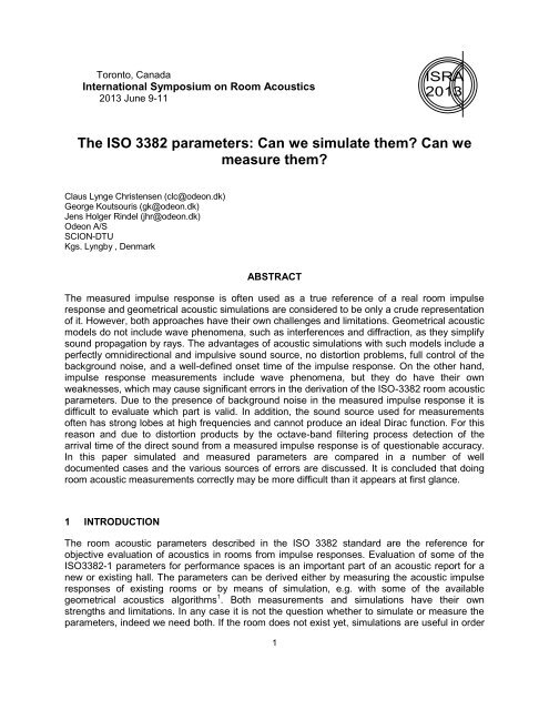
Toronto, Canada<br />
International Symposium on Room Acoustics<br />
2013 June 9-11<br />
ISRA<br />
2013<br />
The ISO 3382 parameters: Can we simulate them? Can we<br />
measure them?<br />
Claus Lynge Christensen (clc@odeon.dk)<br />
George Koutsouris (gk@odeon.dk)<br />
Jens Holger Rindel (jhr@odeon.dk)<br />
<strong>Odeon</strong> A/S<br />
SCION-DTU<br />
Kgs. Lyngby , Denmark<br />
ABSTRACT<br />
The measured impulse response is often used as a true reference of a real room impulse<br />
response and geometrical acoustic simulations are considered to be only a crude representation<br />
of it. However, both approaches have their own challenges and limitations. Geometrical acoustic<br />
models do not include wave phenomena, such as interferences and diffraction, as they simplify<br />
sound propagation by rays. The advantages of acoustic simulations with such models include a<br />
perfectly omnidirectional and impulsive sound source, no distortion problems, full control of the<br />
background noise, and a well-defined onset time of the impulse response. On the other hand,<br />
impulse response measurements include wave phenomena, but they do have their own<br />
weaknesses, which may cause significant errors in the derivation of the ISO-3382 room acoustic<br />
parameters. Due to the presence of background noise in the measured impulse response it is<br />
difficult to evaluate which part is valid. In addition, the sound source used for measurements<br />
often has strong lobes at high frequencies and cannot produce an ideal Dirac function. For this<br />
reason and due to distortion products by the octave-band filtering process detection of the<br />
arrival time of the direct sound from a measured impulse response is of questionable accuracy.<br />
In this <strong>paper</strong> simulated and measured parameters are compared in a number of well<br />
documented cases and the various sources of errors are discussed. It is concluded that doing<br />
room acoustic measurements correctly may be more difficult than it appears at first glance.<br />
1 INTRODUCTION<br />
The room acoustic parameters described in the ISO 3382 standard are the reference for<br />
objective evaluation of acoustics in rooms from impulse responses. Evaluation of some of the<br />
ISO3382-1 parameters for performance spaces is an important part of an acoustic report for a<br />
new or existing hall. The parameters can be derived either by measuring the acoustic impulse<br />
responses of existing rooms or by means of simulation, e.g. with some of the available<br />
geometrical acoustics algorithms 1 . Both measurements and simulations have their own<br />
strengths and limitations. In any case it is not the question whether to simulate or measure the<br />
parameters, indeed we need both. If the room does not exist yet, simulations are useful in order<br />
1
to predict and optimize the acoustics, and when the same room has been built measurements<br />
are useful for documentation. When an existing room is to be refurbished, measurement of<br />
acoustics parameters in the room is an invaluable input in order to objectively evaluate the<br />
acoustics under existing conditions and as input to the simulation process, so that the initial<br />
simulation model can be calibrated to best mimic the existing conditions before starting to<br />
simulate changes. Precision of measurements and simulations are equally important – indeed<br />
making decisions based on imprecise measurement results or calibrating a simulation model to<br />
fit imprecise measurement data is just as bad as imperfect simulations. This has been one of<br />
our major motivations for implementing robust measurement facilities into the ODEON Room<br />
Acoustics Software, which is not too sensitive to user interaction or measurement conditions.<br />
Impulse response measurements are important for the analysis of the acoustics in any kind of<br />
room, small or large, simple or complex. An impulse response is simply the response of a room<br />
to a Dirac function emitted as a sound signal from a source. In principle more than one source<br />
can be used for the impulse response excitation, but for ISO 3382 measurements one and only<br />
one omni-directional source should be used. The ISO 3382 standard give the framework for<br />
measurement of room acoustic parameters, but lack detail on the requirements needed for<br />
derivation of certain room acoustic parameters 2 . One of the major problems is the correct<br />
truncation of the impulse response at the correct time. Any recording of a room impulse<br />
response is likely to have a degree of background noise, due to the ambient noise in the room<br />
and/or to the noise of the measuring equipment. This background noise is visible at the cease of<br />
the impulse response and needs to be left out of the analysis. Otherwise the real energy decay<br />
in the room might be misinterpreted, often leading to longer reverberation times. The truncation<br />
according to ISO 3382 can be done manually, without any guidelines given. This can be a<br />
source of serious errors, if not performed carefully for the different octave bands considered.<br />
Another important aspect in the post-processing of an impulse response is correct detection of<br />
the onset time, i.e., the arrival of direct sound from the source at the receiver – this is tricky as<br />
the real life sound source will not produce a perfect Dirac function. Careless post-processing<br />
can result in large differences between measured and simulated results for parameters such as<br />
clarity C 80 3 :<br />
(1)<br />
where<br />
is the sound pressure as a function of time (pressure impulse response).<br />
In this <strong>paper</strong> a selection of the most important ISO 3382-1 parameters is investigated in terms of<br />
measurements and simulations. The differences are discussed and their significance is<br />
concluded within the frame of the corresponding Just Noticeable Difference – JND. Table 1<br />
shows the parameters used in the present study, together with the respective JND. Both<br />
measurements and simulations are carried out with the ODEON Room Acoustics Software,<br />
version 12.1.<br />
2
Table 1: Room Acoustic Parameters investigated in this <strong>paper</strong>. All parameters are derived by<br />
formulas given in the ISO 3382 standard 3 .<br />
ISO 3382 Parameter Symbol Subjective Limen<br />
Early Decay Time EDT [s] 5%<br />
Reverberation Time 20 T 20 [s] 5%<br />
Reverberation Time 30 T 30 [s] 5%<br />
Clarity C 50 [dB] 1 dB<br />
Clarity C 80 [dB] 1 dB<br />
Definition D 50 0.05<br />
Gravity Time T s [s] 10ms<br />
Sound Strength G [dB] 1 dB<br />
2 IMPULSE RESPONSE SIMULATIONS<br />
Simulations in room acoustics are well known to provide fast and effortless estimation for the<br />
ISO 3382 parameters. They are mainly based on geometrical acoustics algorithms which<br />
simplify the wave phenomena to fundamental geometrical tasks. Phase information is generally<br />
excluded, so that the results can be considered valid for frequencies above Schroeder’s limiting<br />
frequency 4 : [Hz], where is the reverberation time in the room in seconds<br />
and V is its volume in m 3 . Below this limit the modes in a room are very distinct and prominent,<br />
but cannot be accurately predicted, due to the lack of phase information. On the other hand,<br />
above a high modal overlap is present, so that wave effects due to phase can be neglected<br />
without significant loss of information for the acoustic field. Despite their simplified approach,<br />
geometrical acoustic simulations are invaluable for predicting the ISO 3382 parameters in a<br />
wide variety of rooms, from offices and music studios to auditoriums and concert halls. Even<br />
though simulations offer a simplified approach of a real-world sound field they still have a<br />
number of advantages over measurements: The source is perfectly omni-directional, there are<br />
no problems with distortion, there is no background noise so the dynamic range is infinite at all<br />
frequencies, no filtering is required and the results are reproducible if the stochastic nature of<br />
the algorithm used is eliminated (deterministic ray tracing 5 ).<br />
2.1 Modelling the Room – Uncertainty of Input Data<br />
The basis for simulating the impulse response is the digital model of the room. This implies that<br />
the geometry of the room is simplified, sometimes to make a very rough room model only<br />
representing the main shape of the room, and in other cases being a rather close<br />
approximation, if created directly from the architect’s 3D model. However, because of the<br />
3
wavelength of audible sound, the degree of geometrical detail in the room model is generally not<br />
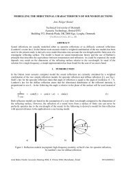
the main source of uncertainty in the simulations. The acoustical data representing the<br />
materials, i.e. the absorption coefficients (α) and the scattering coefficients (s) are often more<br />
important for the uncertainty. The available data for a well defined highly absorbing material,<br />
which has been tested in the laboratory, come with a significant uncertainty (see Table 2 and<br />
Table 3).<br />
Table 2: Uncertainty of measured absorption coefficients.<br />
Frequency, Hz 125 250 500 1000 2000 4000<br />
Type A mounting, α(mean) 0,26 0,85 1,11 1,07 1.02 1,03<br />
Standard deviation 0,070 0,051 0,030 0,040 0,046 0,047<br />
Type E-400 mounting, α (mean) 0,64 0,78 0,98 1,06 1,06 1,06<br />
Standard deviation 0,107 0,053 0,038 0,032 0,035 0,047<br />
Average std.dev. 0,088 0,052 0,034 0,036 0,040 0,047<br />
95% confidence range ± 0,18 ± 0,10 ± 0,07 ± 0,07 ± 0,08 ± 0,09<br />
Table 3: Estimated uncertainty of measured scattering coefficients<br />
Frequency, Hz 125 250 500 1000 2000 4000<br />
Assumed α s 0,25 0,25 0,25 0,25 0,25 0,25<br />
Assumed α spec 0,29 0,33 0,59 0,74 0,83 0,87<br />
s (example) 0,05 0,10 0,45 0,65 0,77 0,83<br />
Standard deviation, δ s 0,04 0,04 0,04 0,04 0,04 0,07<br />
95% confidence range ± 0,08 ± 0,08 ± 0,08 ± 0,08 ± 0,08 ± 0,14<br />
The standard deviation on absorption coefficients is the Inter-laboratory reproducibility from a<br />
Round Robin in 2002 organized by ASTM 6 with 16 participating laboratories. Two different test<br />
samples were applied, a 51 mm thick glass fibre panel, which was either laid directly on the floor<br />
(Type A mounting) or suspended 400 mm from a rigid surface (Type E-400 mounting). The<br />
mean value and the standard deviation between the 16 laboratory results are given in Table 2.<br />
Looking at the 1 kHz octave band as an example, the absorption coefficient reported from a<br />
laboratory test has a 95% confidence range of ± 0.07, which means that with 95% probability<br />
the true value is within this range. In other words, there is a 5% risk that the true absorption<br />
coefficient deviates more than 0.07 from the measured value. At 125 Hz the 95% confidence<br />
range is even higher: ± 0.18. This clearly shows that the absorption data represents a significant<br />
source of uncertainty in any room acoustic calculation, including the traditional use of Sabine’s<br />
equation.<br />
The uncertainty on the scattering coefficient is also worth noting, although the influence on the<br />
uncertainty of the calculation results may be less dramatic as for the absorption. The standard<br />
deviation on scattering coefficients has been calculated here using equation (A5) found in ISO<br />
17497-1 7 and applying data on the Intra-laboratory repeatability on the measurement of<br />
absorption coefficients also reported in 6 . For the purpose of the calculations a typical set of<br />
4
scattering coefficients have been applied, having s = 0.50 at the mid-frequencies (between 500<br />
and 1000 Hz).<br />
Looking at the influence of scattering on the simulated room acoustic parameters, high<br />
scattering coefficients above 0.40 tend to give approximately the same results. However, low<br />
scattering coefficients in the range from 0.00 to 0.10 can have a very strong influence on the<br />
calculation results, and thus should always be regarded carefully. In fact, it is recommended to<br />
look at the scattering coefficients in a logarithmic scale; for example the following steps in<br />
scattering coefficient are approximately of equal importance: 0.40 – 0.20 – 0.10 – 0.05 – 0.025 –<br />
0.0125. Finally, the quality of a simulation result is influenced by the knowledge and experience<br />
of the user. This is particularly important in relation to the input data for the materials.<br />
2.2 Calculation of the impulse response<br />
Although geometrical models for room acoustics simulation can be a fairly complicated matter, it<br />
is much easier to derive ISO 3382 parameters from such a simulation than it is from a real<br />
impulse response measurement: 1) the onset time of the impulse response is well defined from<br />
geometry, 2) there is no need for digital filtering which may blur octave band results in the time<br />
domain and 3) background noise is not a problem. Two types of parameters shall be described<br />
shortly. Decay parameters such as T 30 and time interval parameters such as C 80 .<br />
ODEON makes use of hybrid calculation methods which is based on a combination of the image<br />
source method and a special ray radiosity method in order to predict arrival times of reflections<br />
at a receiver and the strength of reflections in octave bands 5 . The calculation methods are<br />
energy based, so adding the octave band energy to a time histogram forms directly the squared<br />
impulse response which is needed in order to derive parameters such as T 30 and C 80 , without<br />
the need for any digital filtering. The length of the impulse response predicted is usually limited<br />
by maximum path length for which the rays are traced. The early part of the response (early<br />
reflections) is determined by a list of image sources up to a transition order, typically up to 2 nd<br />
order. For higher order reflections a Fibonacci-spiral shooting of rays is initiated, resulting in a<br />
large number of reflection points, distributed on the surfaces of the room. Each point is replaced<br />
by a secondary source, which radiates sound according to the relative strength and delay of the<br />
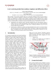
corresponding reflection. An algorithm called reflection and vector based scattering uses as<br />
input data the scattering coefficient of the surface, the distance between the present and the<br />
previous reflection points, as well as the angle of incidence, to produce a unique directivity<br />
pattern for the secondary source 5 . Once all image and secondary sources have been detected,<br />
the energy information they carry can be collected from all visible receivers in the room,<br />
effectively leading to an energy (squared) impulse response.<br />
2.3 Deriving decay parameters<br />
Decay parameters, such as T 30 , can be derived from the squared impulse response. The ISO<br />
3382 standard describes that T 30 can be derived in the following way:<br />
The decay curve is the “graphical representation of the sound pressure level in a room as a<br />
function of time after the sound source has stopped” (interrupted noise assumed). The decay<br />
curve can also be derived from an impulse response measurement using Schroeder’s<br />
backwards integration 8 . This backwards integrated decay curve, derived from an impulse<br />
5
SPL (dB)<br />
response, corresponds to the decay curve obtained from the decay of interrupted noise – if<br />
taking the average of curves from an infinite number of measurements 3 :<br />
(2)<br />
One problem with the backwards integration is that some energy is not included in the real<br />
impulse response due to its finite length t 1 . The problem can be corrected by estimating the<br />
energy that is lost due to the truncation. This amount of energy can be added as an optional<br />
constant C in Eq.(2):<br />
(3)<br />
If the curve is not corrected for truncation, the estimated decay time may be too short.<br />
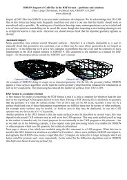
In Figure 1 a simulated decay curve is shown at 1000 Hz. The blue curves are the squared<br />
impulse response in dB and the backwards integrated curve. The black curve is the backwards<br />
integrated curve which has been corrected for truncation. In order to derive a decay parameter,<br />
the appropriate range of the backwards integrated and corrected decay curve is evaluated and<br />
a least-squares fitted line is computed for the range. For T 20 the range is from 5 dB to 25 dB<br />
below the steady state level and for T 30 the range is from 5 dB to 35 dB below the steady state<br />
level. The slope of the fitted line gives the decay rate, d in dB per second, from which the<br />
reverberation time is calculated e.g. as T 30 = 60/d.<br />
Decay curves at 1000 Hz, T(30)=1,90<br />
Zoomed decay T(15,67, -46,26)=1,90 s<br />
15<br />
10<br />
5<br />
0<br />
gfedcb<br />
gfedcb<br />
gfedcb<br />
gfedc<br />
gfedc<br />
E, Simulated<br />
E, Integrated<br />
E, Corrected<br />
I, Simulated<br />
I, Integrated<br />
-5<br />
-10<br />
-15<br />
-20<br />
-25<br />
-30<br />
-35<br />
-40<br />
-45<br />
-50<br />
-55<br />
-60<br />
-65<br />
0<br />
0,1<br />
0,2<br />
0,3<br />
0,4<br />
0,5<br />
0,6<br />
0,7<br />
0,8 0,9 1 1,1<br />
Time (seconds rel. direct sound)<br />
1,2<br />
1,3<br />
1,4<br />
1,5<br />
1,6<br />
1,7<br />
1,8<br />
1,9<br />
<strong>Odeon</strong>©1985-2013 Licensed to: <strong>Odeon</strong><br />
Figure 1: Example of simulated squared impulse response curves and integrated decay curves.<br />
2.4 Deriving Time Interval Parameters<br />
Parameters such as C 80 make use of the energy arriving at the receiver in specific time<br />
intervals, relative to the direct sound. In the case of C 80 (Eq.(1)) the time intervals are from 0 to<br />
80 ms and from 80 ms to infinity, after the arrival of direct sound. In order to make a decent<br />
6
prediction of C 80 it is important that the onset time is well defined. When the source is visible<br />
from the receiver this is not a problem as the onset time can be derived from source and<br />
receiver position and even in slightly coupled spaces this may be precise enough.<br />
Measured time interval parameters may not be precisely derived if calculated directly from the<br />
filtered response, because filters create delay and smear the response in time. This can be<br />
particularly significant for the lower frequency octave bands where the filters are “long”. In order<br />
to bypass this filter problem, ISO 3382-1 suggest the “Window-before-filtering” approach which<br />
is the method implemented in ODEON. First the onset time is estimated from the broad band<br />
impulse response. In order to estimate the energy arriving for example during the first 80 ms,<br />
the first 80 ms of the broad band response arriving after the onset time is gated and octave<br />
band filtered afterwards. This creates a filtered response which is longer than the original broad<br />
band response in order to include the filter tail. Then the energy of the gated filtered response is<br />
counted including the tail of the filter, taking into account most of the smeared energy. Note that<br />
the C 80 parameter may not make sense in a space where receiver and source positions are<br />
strongly decoupled as the build-up of the impulse response may take considerably longer than<br />
the 80 milliseconds.<br />
3 IMPULSE RESPONSE MEASUREMENTS<br />
In contrast to impulse response simulations (Sec.2), measurements may be considered<br />
accurate in a broader frequency area, due to the actual representation of wave phenomena<br />
(interaction due to phase shifts, diffraction etc.). Input data such as absorption and scattering<br />
coefficients are inherent and the room geometry is fully included by definition. On the other<br />
hand, a group of limitations, such as imperfect omni-directional sources, presence of<br />
background noise and distortion due to the filtering required impose errors in the final results.<br />
Table 4 summarizes the facts associated with existing measurement and simulation processes.<br />
The main issues for measurements are those related to the sound source and the background<br />
noise. For the simulations the most important issues are the material data and the<br />
approximation of the wave phenomena.<br />
Table 4: Facts associated to measurements and simulations.<br />
Facts Measurements Simulations<br />
Room geometry Fully included by definition Approximated<br />
Alteration of room geometry Difficult Easy<br />
Wave phenomena (phase<br />
information, diffraction)<br />
Wall properties<br />
Fully included – inherent in<br />
the real sound field<br />
Fully included – inherent in<br />
the real room<br />
Approximated with varying<br />
accuracy<br />
Absorption - scattering<br />
coefficients have to measured<br />
or assumed, with limited<br />
accuracy<br />
7
Air absorption (a function of<br />
temperature and humidity)<br />
Source directivity<br />
Dynamic range of source<br />
Calibration of source<br />
Background Noise<br />
Microphone directivity<br />
Results in different octavebands<br />
Reproducibility<br />
Influence of operator<br />
Fully included but may vary<br />
significantly in different<br />
measurements<br />
Not perfect: Lobes at high<br />
frequencies<br />
Insufficient at very low and<br />
very high frequencies<br />
Distortion at high levels<br />
Special procedure needed for<br />
the G parameter<br />
Present and limits the<br />
dynamic range<br />
Omnidirectional microphone<br />
Some parameters require<br />
figure-of eight pattern or a<br />
dummy head<br />
Filtering is required, which<br />
alters the original signal<br />
Not perfect: Depends heavily<br />
on the source<br />
Knowledge and experience<br />
important<br />
Calculated from theoretical<br />
formulas, but very accurate<br />
Perfectly omni-directional<br />
Unlimited dynamic range at all<br />
frequencies<br />
No distortion<br />
Perfect per definition<br />
Not present<br />
All directivities available<br />
Results are derived directly in<br />
different bands - no alteration<br />
due to filtering.<br />
Can be perfect, depending on<br />
the algorithm<br />
Knowledge and experience<br />
very important<br />
3.1 Measuring an Impulse Response<br />
An impulse response can be obtained directly by recording the response to hand-clapping,<br />
popping of a balloon/<strong>paper</strong>-bag, a gunshot or even a hard footstep. As a modern alternative an<br />
impulse response can be obtained indirectly by producing a Maximum Length Sequence (MLS)<br />
or a sweep signal using an electro acoustic source. The latter methods stretches the impulse<br />
(Dirac function) in time and the measured response is deconvolved in order to form the impulse<br />
response. Using time stretched excitation, a substantial amount of energy is emitted from an<br />
electro acoustic source with limited maximum acoustic output, allowing superior signal to noise<br />
ratio. Reproducibility is also easier to control with electro-acoustic stimuli, due to uniform<br />
radiation.<br />
Among the many available measurement methods the preferred one today is the swept sine<br />
method using a rather long exponential sweep 9 . This method can produce impulse responses<br />
with very good dynamic range and minimized harmonic distortion by the loudspeaker. Still there<br />
8
SPL(dB)<br />
can be some influence from non-harmonic distortion 10,11 . Figure 2 shows an example of<br />
squared impulse response with indication of estimated noise floor and truncation time.<br />
D:\Measured Impulse responses\isra_measurements1\Auditorium21GEorgeClaus15feb2013\s1r1_4000.wav<br />
Raw decay curve at 4000Hz<br />
-8<br />
-10<br />
-12<br />
-14<br />
-16<br />
-18<br />
-20<br />
-22<br />
-24<br />
-26<br />
-28<br />
-30<br />
-32<br />
-34<br />
-36<br />
-38<br />
-40<br />
-42<br />
-44<br />
-46<br />
-48<br />
-50<br />
-52<br />
-54<br />
-56<br />
-58<br />
-60<br />
-62<br />
-64<br />
-66<br />
T t<br />
Noise floor<br />
gfedcb<br />
gfedcb<br />
gfedcb<br />
gfedcb<br />
E, Measured<br />
Noise floor<br />
Onset time<br />
Truncation time<br />
-0.2 0 0.2 0.4 0.6<br />
<strong>Odeon</strong>©1985-2013 Licensed to: <strong>Odeon</strong> A/S<br />
0.8<br />
1<br />
1.2<br />
1.4<br />
1.6 1.8 2<br />
time (seconds)<br />
2.2<br />
2.4<br />
2.6<br />
2.8<br />
3<br />
3.2<br />
3.4<br />
3.6<br />
3.8<br />
Figure 2: An impulse response with background noise and correct truncation (cross) point T t.<br />
3.2 Filtering the Impulse Response<br />
The octave-band filters typically used in the processing of room impulse responses are 2 nd order<br />
Butterworth filters in accordance with the IEC 61260 12 . These analogue filters can be<br />
implemented using digital infinite impulse response (IIR) filters. ODEON uses such type of filters<br />
and defines a finite effective length, allowing 99.9% of the energy in the tail of the filtered<br />
impulse response to be included. The filtering process introduces unwanted transient effects in<br />
the beginning of the response, which cease after about one effective length of the filter.<br />
A reverse filtering algorithm is applied for decay analysis (Sec.2.3) so that all the transients are<br />
re-positioned at the tail of the impulse response. ODEON automatically excludes this transient<br />
tail when processing the impulse response. The reverse method has also the advantage of<br />
eliminating the stretching of the filtered signal, which occurs due to the delay of the filter itself.<br />
This stretching effectively leads to energy smearing, altering the slope of the decay curve. After<br />
processing the signal with reverse filtering, an extra forward filtering is applied, allowing for<br />
suppression of phase distortion. This combination of reverse-forward filtering in the decay<br />
analysis is used for the calculation of decay parameters, such as T 30 . For the time interval<br />
parameters (Sec.2.4) only forward filtering is applied for each gated window. The smearing of<br />
the energy is precluded by taking into account the effective length of the filter at the end of each<br />
window, as extra impulse response time.<br />
9
SPL(dB)<br />
3.3 Detecting the Onset Time<br />
An ideal impulse response, according to geometrical acoustics 1 , would consist of an ensemble<br />
of Dirac functions with appropriate delays and strengths. The ideal direct sound from a source<br />
should be a perfect Dirac function too, arriving at a time equivalent to the distance between the<br />
source and the receiver. However in reality the direct sound and all the other reflections are not<br />
perfect Dirac functions. In fact, each reflection consists of an onset (before the peak value), a<br />
peak and some decay. As the frequency gets lower, the decay of a reflection may overlap with<br />
the onset of a subsequent reflection. In the derivation of many of the ISO 3382 parameters it is<br />
vital to capture the amount of early energy correctly. ODEON uses advanced algorithms for<br />
successfully detecting the energy from the direct sound and discriminating it from the following<br />
reflections. For every impulse response the detected onset time is indicated in the display.<br />
According to the ISO 3382-1 standard 3, pp. 18-19 the onset of the direct sound and of the whole<br />
impulse response should be at least 20 dB below the peak of the direct sound. In ODEON this<br />
value is called Trigger level and by default is set to 40 dB. This number is automatically<br />
moderated if the trigger point is getting too close to the noise floor. The onset time is detected<br />
from the broad band impulse response as suggested in the above reference.<br />
\Claus\Documents\<strong>Odeon</strong> filer\Measurements\isra_measurements1\Auditorium21GEorgeClaus15feb2013\s2r5_georges handclaps.wav<br />
Raw decay curve at 1000Hz<br />
20<br />
15<br />
10<br />
5<br />
0<br />
gfedcb<br />
gfedcb<br />
gfedcb<br />
gfedcb<br />
E, Measured<br />
Noise floor<br />
Onset time<br />
Truncation time<br />
-5<br />
-10<br />
-15<br />
-20<br />
-25<br />
-30<br />
-35<br />
-12 -10 -8<br />
<strong>Odeon</strong>©1985-2013 Licensed to: <strong>Odeon</strong><br />
-6<br />
-4 -2<br />
time (seconds)<br />
0<br />
2<br />
4<br />
Figure 3: Display of onset time and truncation time at 1000 Hz for a series of handclaps. The<br />
recording contains multiple impulse responses – ODEON chooses the one with the maximum<br />
broad band peak level.<br />
In the ODEON software both the trigger level and a number of other parameters can be set<br />
manually in order to provide the flexibility to the user to control the onset time. However the<br />
default value of -40 dB for the trigger level seems to work well. A short time interval, the Noise<br />
floor window length, can be specified for the detection of noise floor before the onset time. This<br />
10
is used for separating multiple impulse response from each other or indeed to exclude small<br />
amounts of impulsive noise - the default value of 10 ms for the Noise floor window length seems<br />
to work well too.<br />
3.4 Noise Floor and Truncation of the Impulse Response<br />
When measuring an impulse response the dynamic range is limited by background noise which<br />
may influence all parameters that can be derived from the impulse response significantly if its<br />
level isn’t very low or compensated for. At some time after the onset time the impulse response<br />
will decay to the level of the noise floor and the rest of the recorded response is not valid – this<br />
time we denote truncation time. The Truncation time is unique to each band of interest. The<br />
energy of noise arriving after the Truncation time should be excluded from analysis; however<br />
energy before it is also influenced by noise. Most of the impulse response recordings, whether<br />
recorded directly or obtained using the sweep method, come with a noticeable noise tail, due to<br />
the ambient background noise and noise of the transmission line involved (PC sound card,<br />
cables and microphone). This noise tail should be removed before deriving the decay curve and<br />
the ISO 3382 room acoustic parameters. Lundeby et al. have proposed an algorithm for<br />
detecting the noise floor and truncating the recording at the cross-point between the pure<br />
impulse response and the noise floor 13 . The cross-point is estimated by an iteration process of<br />
impulse response smoothing and regression line fitting. The ODEON measurement system<br />
utilizes a modification of this method in order to estimate the appropriate truncation time for<br />
each octave-band.<br />
3.5 Decay Curve and Noise Correction<br />
Still the background noise is present in the backwards integrated decay curve in the range<br />
between the onset time and the truncation time and this will result in an over estimation of the<br />
decay time when the energy contained in the noise floor is not negligible. However this may also<br />
be compensated for if the level of the noise floor is well estimated. Apart from the tail correction<br />
we suggest that the estimated background noise floor excluding the truncated tail (Sec.3.4) can<br />
be subtracted from the valid part of the backwards integrated decay curve.<br />
4 INVESTIGATIONS ON MEASUREMENTS<br />
Two different rooms are studied in this investigation an auditorium and Hagia Sophia, a large<br />
mosque/cathedral in Istanbul. The first room falls within the category of rooms that are typically<br />
investigated using the ISO 3382-1 standard, where the latter is a large space with many coupled<br />
volumes where it is a bigger challenge to make simulations and measurements of the ISO 3382-<br />
1 parameters agree.<br />
The auditorium was Auditorium 21 at the Technical University of Denmark which is used for<br />
lectures. This auditorium was chosen because it was accessible for measurements and not for<br />
its excellent acoustics conditions. A model of the room consisting of 198 surfaces was modelled<br />
11
in Trimble Sketchup a . We normally model the audience area with a limited level of detail e.g. as<br />
a plane with skirts as this area is normally highly absorbing and scattering. In this room however<br />
in the unoccupied state the audience area consists of hard wooden chairs and desks. It was<br />
found that a model with a more detail audience area gave better agreements between<br />
simulations and measurements so the more detailed version of the audience area was included<br />
in this study. Initial materials were selected according to a visual inspection of the room and<br />
absorption coefficients were fine tuned in order to match average measured and simulated T 30<br />
values.<br />
In this auditorium we examine:<br />
<br />
<br />
<br />
<br />
The influence of different signal to noise ratios on the obtained measurement results by<br />
using different sweep lengths.<br />
Whether meaningful measurement results can be obtained using different excitation signals<br />
(sweep, hand claps, popping balloons).<br />
The sensitivity to uncertainty of exact receiver position on measured and simulated<br />
parameters.<br />
Measured and simulated parameters for a number of receiver positions.<br />
Figure 4: Horizontal directivity pattern of the Dodecahedron Loudspeaker D12, by LANGE<br />
Loudspeakers, at 2000 and 4000 Hz.<br />
For the impulse response series obtained with ODEON a dodecahedron omni-directional source<br />
was employed. Figure 4 shows the directivity pattern for such a source by LANGE<br />
Loudspeakers b . It can be seen that at 2000 and 4000 Hz the source is not perfectly omnidirectional.<br />
a http://www.sketchup.com<br />
b http://www.langeloudspeakers.com<br />
12
p x E-1<br />
Impulse response recordings were made and processed with ODEON 12.1 for 2 sources (P)<br />
and 5 receiver (R) positions, giving a total of 10 combinations in accordance with the ISO 3382-<br />
1 standard 3 . The following study is focused only on the results from source one (P1). A<br />
perspective view of the auditorium, together with a ground plan and the source-receiver<br />
positions is displayed in Figure 5. The impulse responses were recorded with an exponential<br />
sweep signal. Figure 6 shows an example of the impulse response for the combination S1-P1<br />
at 4000 Hz. Room acoustic parameters described in ISO 3382-1 3 where derived.<br />
0 3 5 8 10 13 metres<br />
1<br />
5 metres<br />
3<br />
P1<br />
5<br />
0<br />
4<br />
2<br />
<strong>Odeon</strong>©1985-2013 Licensed to: <strong>Odeon</strong><br />
<strong>Odeon</strong>©1985-2013 Licensed to: <strong>Odeon</strong><br />
Figure 5: Model of the auditorium 21 at the Technical University of Denmark, as it appears<br />
inside ODEON. Left: Three-dimensional rendering of Auditorium 21 with colors corresponding to<br />
the reflectance of the surfaces 14 . Right: Source and receiver positions inside auditorium 21.<br />
D:\Measured Impulse responses\isra_measurements1\Auditorium21GEorgeClaus15feb2013\s1r1_4000.wav<br />
Ray Impulse response at 4000Hz<br />
4<br />
3.5<br />
3<br />
2.5<br />
2<br />
1.5<br />
1<br />
0.5<br />
gfedcb<br />
gfedcb<br />
gfedcb<br />
Omni microphone<br />
Onset time<br />
Truncation time<br />
0<br />
-0.5<br />
-1<br />
-1.5<br />
-2<br />
-2.5<br />
-3<br />
-3.5<br />
-4<br />
-4.5<br />
-0.2 -0.1 0 0.1 0.2<br />
<strong>Odeon</strong>©1985-2013 Licensed to: <strong>Odeon</strong> A/S<br />
0.3<br />
0.4 0.5 0.6 0.7 0.8<br />
time (seconds incl. filter delay)<br />
0.9<br />
1<br />
1.1<br />
1.2<br />
1.3<br />
Figure 6: Typical impulse response obtained with the sweep method in ODEON. Combination<br />
S1-R1 at 4000 Hz.<br />
13
T30 (s)<br />
4.1 Varying Sweep Length<br />
For the combination P1-R5 the different impulse responses were obtained with sweep lengths of<br />
0.5, 1, 2, 4, 8, 16 and 32 sec in order to evaluate whether the signal to noise ratio (S/N)<br />
increases by 3 dB per doubling of sweep length, as expected, and to evaluate the impact on<br />
derived values of T 30 . These measurements were performed at very low level in order to obtain<br />
a wide span of S/N levels in the recorded impulse responses. The values of D 50 and C 80 only<br />
showed small differences with increasing sweep lengths. Thus, are not displayed. T 30 did show<br />
some changes with increasing sweep lengths. Three approaches for deriving T 30 were tested: 1)<br />
T 30 derived directly from the backwards integrated curve with no corrections, 2) T 30 derived from<br />
the curve with correction for truncation according to Eq.(3) and finally 3) T 30 derived from the<br />
curve with correction for truncation, as well as correction for noise floor in the valid part of the<br />
impulse response, as described in 3.5.<br />
2,1<br />
2<br />
1,9<br />
1,8<br />
1,7<br />
T30, no correction<br />
T30, truncation<br />
T30,truncation+noise<br />
1,6<br />
1,5<br />
0,05 0,1 0,125 0,25 0,5 1 2 4 8 16 32 512<br />
Length of sweep (s)<br />
Figure 7: T 30, 1000 Hz derived from measured impulse responses with increasing sweep lengths<br />
and with and without correction for impulse response truncation and noise floor.<br />
In Figure 7 it can be seen that for long sweep lengths/high dynamic range all three methods<br />
agree that T 30 is 1.89 s. When T 30 is derived without compensation for truncation of the impulse<br />
response, the values derived are without a doubt too low for short sweep lengths. For the<br />
inexperienced this can be problematic as the uncorrected curve does provide a (wrong) result<br />
for T 30 where as corrected curves will not allow deriving T 30 . If compensating for the truncation of<br />
the impulse response only then T 30 tends to become too long. When the backwards integrated<br />
curve is compensated for background noise, the result stabilizes much faster at the “correct”<br />
value. This is the method implemented in ODEON 12.1.<br />
In Figure 8 the dynamic range - SPL/Noise, corresponding to the sweep length used in Figure<br />
7 is given. The SPL/Noise is displayed for any impulse response analyzed in ODEON and it is<br />
14
SPL / Noise (dB)<br />
an indicator whether sufficient S/N was present during the impulse response measurement. The<br />
S/N can be increased either by using a higher output on the loudspeaker, by increasing the<br />
sweep length or by using better equipment (cables, sound card etc.). As can be seen the graph<br />
forms an almost straight line indicating an increase in S/N by 3 dB per doubling of sweep length,<br />
which is expected from the sweep-method theory 15 .<br />
105<br />
100<br />
95<br />
90<br />
85<br />
80<br />
75<br />
70<br />
65<br />
60<br />
0,04 0,16 0,63 2,50 10,00 40,00 160,00 640,00<br />
Length of sweep (s)<br />
Figure 8: Measured Signal to Noise ratio with varying length of sweep.<br />
4.2 Uncertainty of position<br />
In practice it is not possible to position the microphone (nor the source) at an exact position<br />
when conducting room acoustic measurements. So, if reproducing the measurement at a later<br />
time slightly different results in terms of ISO3382-1 parameters should be expected. When a<br />
person is sitting in the auditorium the position will not be exact either. In order to give an idea of<br />
the uncertainty of measured parameters if the receiver position is not exact, measurements in a<br />
region close to receiver position 5 in the middle of the audience area was repeated with position<br />
offsets 30 cm right, 30 cm left, 15 cm front, 15 cm back, 10 cm up, and 10 cm down – a total of<br />
7 positions including the original position. The graphs below (Figure 9 to Figure 14) show<br />
statistics for the 7 positions for each of the parameters EDT, T 30 , Ts, D 50 and C 80 . Measured as<br />
well as simulated results are included for comparison. As can be seen the simulated values in<br />
receiver positions that are close to each other only show minor deviations, much less than<br />
deviations between the measured results, probably because phase is not included in the<br />
simulation model. However, as will be seen later, the simulated results do indeed differ between<br />
the significantly spaced receiver positions 1-5.<br />
15
T(30) (s)<br />
EDT (s)<br />
The T 30 value in Figure 10 shows a standard deviation of 0,02 seconds (0.2 JND) at 1000 Hz,<br />
increasing to 0.09 seconds at 125 Hz so it only varies little with position and should be easy to<br />
reproduce even if position is not exact. This agrees with the idea that T 30 should be a global<br />
value that relates to the room not to a local position. All other parameters do show larger<br />
deviations and with some increases in deviations towards lower frequencies. The standard<br />
deviation for the other parameters are however not as big as one may think when visually<br />
inspecting the graphs. At 1000 Hz none of parameters have a standard deviation larger than 0.7<br />
when normalized to Just Noticeable Differences (JND) and even at 125 Hz all parameters<br />
except SPL (the G value obtained with a source power of 31 dB) have a standard deviation less<br />
than 1.2 JND’s.<br />
Statistics<br />
Active receivers: 5,10,11,12,13,14,15<br />
2<br />
1,8<br />
1,6<br />
1,4<br />
1,2<br />
1<br />
gfedcb<br />
gfedcb<br />
gfedcb<br />
gfedcb<br />
gfedcb<br />
gfedcb<br />
gfedcb<br />
gfedcb<br />
Simulated Avr.<br />
Simulated Min<br />
Simulated Max<br />
Simulated Std. dev.<br />
Measured Avr.<br />
Measured Min<br />
Measured Max<br />
Measured Std. dev.<br />
0,8<br />
0,6<br />
0,4<br />
0,2<br />
0<br />
125 250 500 1000 2000 4000<br />
Frequency<br />
<strong>Odeon</strong>©1985-2013 Licensed to: <strong>Odeon</strong><br />
Figure 9: Uncertainty of position. Statistics on early decay time, EDT.<br />
Statistics<br />
Active receivers: 5,10,11,12,13,14,15<br />
1,9<br />
1,8<br />
1,7<br />
1,6<br />
1,5<br />
1,4<br />
1,3<br />
1,2<br />
1,1<br />
1<br />
0,9<br />
0,8<br />
0,7<br />
0,6<br />
0,5<br />
0,4<br />
0,3<br />
0,2<br />
0,1<br />
gfedcb<br />
gfedcb<br />
gfedcb<br />
gfedcb<br />
gfedcb<br />
gfedcb<br />
gfedcb<br />
gfedcb<br />
Simulated Avr.<br />
Simulated Min<br />
Simulated Max<br />
Simulated Std. dev.<br />
Measured Avr.<br />
Measured Min<br />
Measured Max<br />
Measured Std. dev.<br />
125 250 500 1000 2000 4000<br />
Frequency<br />
<strong>Odeon</strong>©1985-2013 Licensed to: <strong>Odeon</strong><br />
Figure 10: Uncertainty of position. Statistics on reverberation time, T 30 .<br />
16
Ts (ms)<br />
SPL (dB)<br />
Statistics<br />
Active receivers: 5,10,11,12,13,14,15<br />
18<br />
17<br />
16<br />
15<br />
14<br />
13<br />
gfedcb<br />
gfedcb<br />
gfedcb<br />
gfedcb<br />
gfedcb<br />
gfedcb<br />
gfedcb<br />
gfedcb<br />
Simulated Avr.<br />
Simulated Min<br />
Simulated Max<br />
Simulated Std. dev.<br />
Measured Avr.<br />
Measured Min<br />
Measured Max<br />
Measured Std. dev.<br />
12<br />
11<br />
10<br />
9<br />
8<br />
125 250 500 1000 2000 4000<br />
Frequency<br />
<strong>Odeon</strong>©1985-2013 Licensed to: <strong>Odeon</strong><br />
Figure 11: Uncertainty of position. Statistics on sound strength, SPL.<br />
Statistics<br />
Active receivers: 5,10,11,12,13,14,15<br />
150<br />
140<br />
130<br />
120<br />
110<br />
100<br />
90<br />
80<br />
70<br />
60<br />
50<br />
40<br />
30<br />
20<br />
10<br />
0<br />
125 250 500 1000 2000 4000<br />
Frequency<br />
<strong>Odeon</strong>©1985-2013 Licensed to: <strong>Odeon</strong><br />
gfedcb<br />
gfedcb<br />
gfedcb<br />
gfedcb<br />
gfedcb<br />
gfedcb<br />
gfedcb<br />
gfedcb<br />
Simulated Avr.<br />
Simulated Min<br />
Simulated Max<br />
Simulated Std. dev.<br />
Measured Avr.<br />
Measured Min<br />
Measured Max<br />
Measured Std. dev.<br />
Figure 12: Uncertainty of position. Statistics on gravity time, Ts.<br />
17
C(80) (dB)<br />
D(50)<br />
Statistics<br />
Active receivers: 5,10,11,12,13,14,15<br />
0,75<br />
0,7<br />
0,65<br />
0,6<br />
0,55<br />
0,5<br />
0,45<br />
0,4<br />
0,35<br />
0,3<br />
0,25<br />
0,2<br />
0,15<br />
0,1<br />
0,05<br />
gfedcb<br />
gfedcb<br />
gfedcb<br />
gfedcb<br />
gfedcb<br />
gfedcb<br />
gfedcb<br />
gfedcb<br />
Simulated Avr.<br />
Simulated Min<br />
Simulated Max<br />
Simulated Std. dev.<br />
Measured Avr.<br />
Measured Min<br />
Measured Max<br />
Measured Std. dev.<br />
125 250 500 1000 2000 4000<br />
Frequency<br />
<strong>Odeon</strong>©1985-2013 Licensed to: <strong>Odeon</strong><br />
10<br />
9<br />
8<br />
7<br />
6<br />
5<br />
4<br />
Figure 13: Uncertainty of position. Statistics on gravity time, D 50 .<br />
Statistics<br />
Active receivers: 5,10,11,12,13,14,15<br />
gfedcb<br />
gfedcb<br />
gfedcb<br />
gfedcb<br />
gfedcb<br />
gfedcb<br />
gfedcb<br />
gfedcb<br />
Simulated Avr.<br />
Simulated Min<br />
Simulated Max<br />
Simulated Std. dev.<br />
Measured Avr.<br />
Measured Min<br />
Measured Max<br />
Measured Std. dev.<br />
3<br />
2<br />
1<br />
0<br />
-1<br />
125 250 500 1000 2000 4000<br />
Frequency<br />
<strong>Odeon</strong>©1985-2013 Licensed to: <strong>Odeon</strong><br />
Figure 14: Uncertainty of position. Statistics on gravity time, C 80 .<br />
18
4.3 Different excitation stimuli<br />
For the best quality of measurements the sweep method is recommended. However for<br />
surveys, it may be convenient to use a simpler approach e.g. to record and analyse hand claps,<br />
popping of balloons/<strong>paper</strong> bags etc. To get an idea how this works when the recorded<br />
measurements are analysed in ODEON we recorded a series of hand claps (Figure 3), popping<br />
of three balloons and as a reference an impulse response obtained from a 4 seconds long<br />
sweep with sufficient signal to noise ratio.<br />
As can be seen in Table 5 the T 30 values obtained with balloons are in fine agreement with the<br />
sweep method. For the rest of the parameters there are some, though not large, differences<br />
from the values obtained with the sweep signal, probably mainly because the source (a person<br />
popping a balloon) is far from being an omni-directional source. There was some deviation<br />
between the T 30 value obtained by hand clap and with the sweep method – it is very likely that<br />
this is due to insufficient S/N – in fact ODEON was not able to estimate the level of the noise<br />
floor which is why the line displaying the noise floor in (Figure 3) is dotted – thus the T 30 value is<br />
expected to be too long as concluded in section 4.1 – the volume of auditorium 21 is to large to<br />
be excited with this stimuli.<br />
Table 5: Values of eight room acoustic parameters at 1000 Hz obtained by impulse responses<br />
from different stimuli: Hand-clap, popping a balloon and sweep signal (reference measurement).<br />
Hand Clap Balloon 1 Balloon 2 Balloon 3 Sweep 4 s<br />
EDT [s] 2.00 1.7 2.00 1.73 1.87<br />
T 20 [s] 2.01 1.92 1.87 1.92 1.80<br />
T 30 [s] 1.98 1.87 1.89 1.89 1.88<br />
C 50 [dB] -3.8 -3.6 -3.7 -5.1 -2.0<br />
C 80 [dB] -1.4 -0.6 -1.1 -1.7 -0.30<br />
D 50 0.30 0.30 0.30 0.24 0.39<br />
T s [s] 145 124 143 140 127<br />
19
5 COMPARISON OF SIMULATED AND MEASURED RESULTS<br />
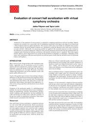
5.1 Auditorium 21<br />
In Figure 15 measured and simulated values of EDT, T 30 , SPL (the G value with a source<br />
power of 31 dB), T s , C 80 and D 50 are displayed for P1 and five receiver positions at 1000 Hz. In<br />
addition an extra frequency band (125 Hz) is displayed for C 80 .<br />
The agreement between measured and simulated parameters at 1000 Hz is within 0.5 JND for<br />
most parameters which is very satisfactory. The difference between measured and simulated<br />
EDT varies from 0.01 to 0.07 seconds with an average deviation of 0.52 JND. As for T 30 , the<br />
difference between measured and simulated values varies from 0.01 to 0.03 seconds with an<br />
average deviation of 0.16 JND (it should be noted that the model was calibrated to match the<br />
average T 30 ). It is interesting to see that both measured and simulated values of EDT (1.98 and<br />
1.96 seconds) are marginally higher that T 30 (1.89 and 1.91 seconds) so this undesired feature<br />
is detected in simulations as well as in the real room. Values of measured and simulated SPL,<br />
Ts, C 80 and D 50 are all in good agreement - and measured and simulated values agree on the<br />
variation with position. There is not space for graphs displaying the rest of the octave bands<br />
from 125 to 4000 Hz, but except for the 125 and 250 Hz band, which shows deviations above 1<br />
JND, there seems to be a fine agreement here too.<br />
20
R3 at 4,55 m<br />
R2 at 6,84 m<br />
R5 at 8,95 m<br />
R1 at 10,12 m<br />
R4 at 12,76 m<br />
R3 at 4,55 m<br />
R2 at 6,84 m<br />
R5 at 8,95 m<br />
R1 at 10,12 m<br />
R4 at 12,76 m<br />
C(80) (dB)<br />
D(50)<br />
R3 at 4,55 m<br />
R2 at 6,84 m<br />
R5 at 8,95 m<br />
R1 at 10,12 m<br />
R4 at 12,76 m<br />
R3 at 4,55 m<br />
R2 at 6,84 m<br />
R5 at 8,95 m<br />
R1 at 10,12 m<br />
R4 at 12,76 m<br />
SPL (dB)<br />
Ts (ms)<br />
R3 at 4,55 m<br />
R2 at 6,84 m<br />
R5 at 8,95 m<br />
R1 at 10,12 m<br />
R4 at 12,76 m<br />
R3 at 4,55 m<br />
R2 at 6,84 m<br />
R5 at 8,95 m<br />
R1 at 10,12 m<br />
R4 at 12,76 m<br />
EDT (s)<br />
T(30) (s)<br />
EDT at 1000 Hz<br />
T(30) at 1000 Hz<br />
2,4<br />
2,2<br />
Simulated 2,1<br />
Measured<br />
2<br />
Simulated<br />
Measured<br />
2<br />
1,8<br />
1,6<br />
1,9<br />
1,8<br />
1,7<br />
Distance<br />
<strong>Odeon</strong>©1985-2013 Licensed SPL at 1000 to: <strong>Odeon</strong> Hz<br />
20<br />
Distance<br />
<strong>Odeon</strong>©1985-2013 Licensed<br />
Ts at 1000<br />
to:<br />
Hz<br />
<strong>Odeon</strong><br />
Simulated<br />
Measured 180<br />
Simulated<br />
Measured<br />
18<br />
16<br />
14<br />
12<br />
160<br />
140<br />
120<br />
100<br />
Distance<br />
<strong>Odeon</strong>©1985-2013 C(80) Licensed at 1000 to: <strong>Odeon</strong> Hz<br />
2<br />
1<br />
0<br />
-1<br />
Distance<br />
<strong>Odeon</strong>©1985-2013 Licensed to: <strong>Odeon</strong><br />
D(50) at 1000 Hz<br />
0,6<br />
Simulated<br />
Measured<br />
0,5<br />
0,4<br />
Simulated<br />
Measured<br />
-2<br />
-3<br />
0,3<br />
0,2<br />
Distance<br />
<strong>Odeon</strong>©1985-2013 Licensed to: <strong>Odeon</strong><br />
Distance<br />
<strong>Odeon</strong>©1985-2013 Licensed to: <strong>Odeon</strong><br />
Figure 15: Simulated and measured room acoustic parameters for the five receivers in<br />
auditorium 21. Simulated parameters displayed with red square and measurements with blue<br />
cross.<br />
21
5.2 Hagia Sophia<br />
The second room studied is Hagia Sophia a large mosque/cathedral in Istanbul. This room has<br />
a length of almost 100 metres, a height of approximately 54 metres, a total volume around<br />
200000 m 3 containing many coupled volumes and a reverberation time in the mid-frequency<br />
range close to 10 seconds. Hagia Sofia may be considered a performance space but not the<br />
typical auditorium for which ISO 3382-1 is probably intended. Therefore it is reasonable to<br />
expect that it is more difficult to find agreement between measured and simulated ISO 3382-1<br />
parameters in this type of room and some of the parameters may have limited use.<br />
Hagia Sophia was studied as part of the CAHRISMA project (Conservation of the Acoustical<br />
Heritage by the Revival and Identification of the Sinan’s Mosques’ Acoustics) a three-year<br />
project financed by the EU. In the CAHRISMA project room acoustics modeling and<br />
measurements were conducted on a number of mosques and byzantine churches according to<br />
ISO 3382. The modeling was done in the ODEON software and measurements were done with<br />
some MATLAB code that was created during the project. The measured impulse responses are<br />
still available so we have analyzed them with our current measurement system – though we do<br />
not have the calibration data for evaluation of the G parameter.<br />
In the CAHRISMA project there was fine agreement between measured and simulated values of<br />
reverberation parameters and SPL however parameters such as Ts, D 50 , and C 80 were in pretty<br />
bad agreement for many positions. Some of the reason probably being that detection of onset<br />
time in measurements was not reliable and that parameters such as C 80 were derived directly<br />
from the octave band filtered impulse response without “Window-before-filtering” as<br />
recommended by the current ISO 3382-1 – some of the C 80 values were off by more than 12 dB!<br />
It must be noted that 6 of the 11 measurement positions presented here were located in distant<br />
galleries without any sight to the source and that a parameter like C 80 is probably not a good<br />
indicator in such locations – still it is comforting for the user of simulation and measurement<br />
software that the output of simulation and measurements are in agreement.<br />
0 20 40 60 metres<br />
50 metres<br />
812 7 11 610<br />
40<br />
30<br />
P1<br />
1<br />
2<br />
P3<br />
4<br />
5<br />
9<br />
20<br />
3<br />
P2<br />
10<br />
0<br />
<strong>Odeon</strong>©1985-2013 Licensed to: <strong>Odeon</strong><br />
<strong>Odeon</strong>©1985-2013 Licensed to: <strong>Odeon</strong><br />
Figure 16: Left: Three-dimensional rendering of Hagia Sophia with colors corresponding to the<br />
reflectance of the surfaces [14]. Right: Ground-plan of Hagia Sophia.<br />
22
In Figure 16 measured and simulated values of EDT, T 30 , T s , C 80 and D 50 are displayed for P1<br />
and 11 receiver positions at 1000 Hz. In addition an extra frequency band (125 Hz) is displayed<br />
for C 80 .<br />
The difference between measured and simulated parameters at 1000 Hz are larger in terms of<br />
JND’s for Hagia Sofia than was the case for Auditorium 21 however the span for some of the<br />
parameters are also much larger than is the case for a normal auditorium.<br />
For EDT the difference between measured and simulated values differs between 0.01 and 3.49<br />
JND’s. The biggest deviation is found at the receiver point where source and receiver are very<br />
close to each other which is 16 meters in this large room! Indeed the first 8 dB of the measured<br />
backwards integrated curve is very steep because it is influenced by direct sound. The average<br />
deviation between measured and simulated EDT for the 11 positions is 1.15 JND.<br />
As for T 30 , the difference between measured and simulated values differs between 0.11 and<br />
0.54 JND’s with an average difference of 0.22 JND’s. Both simulations and measurements<br />
shows that T 30 is almost a constant throughout the whole volume although the space consists<br />
many coupled volumes and some of the receivers are located at very remote positions.<br />
The measured and simulated values of Ts in the 11 positions follow the same trends with<br />
position and vary substantially in the volume from 233 to 975 milliseconds. Using the JND of 10<br />
ms for Ts as given in ISO 3382-1 would suggest that there are large deviations between<br />
measured and simulated values of Ts however this value is highly questionable for a room with<br />
this volume and reverberation time – maybe a relative value of 5 % would be more meaningful.<br />
The D 50 parameter is within 1.19 JND for eight of the eleven positions. The three last positions<br />
are within 2.28 JND’s.<br />
C 80 has a deviation ranging from 0.47 to 4.66 JND’s with an average deviation of 2.27. One may<br />
say that this deviation is very high however considering that C 80 in the 11 positions ranges from<br />
-18.8 to 4.8 dB it shows a much higher fluctuation than in a normal auditorium. In any case one<br />
should be careful using parameters such as C 80 for evaluation of C 80 in coupled spaces such as<br />
Hagia Sofia as the buildup of the squared impulse response by far exceeds the 80 milliseconds<br />
time limit used for the C 80 parameter.<br />
There is not space for graphs displaying the rest of the octave bands from 125 to 4000 Hz, but<br />
the agreement between measured and simulated values are fairly similar to those of the 1000<br />
Hz band.<br />
23
R2 at 16,63 m<br />
R8 at 29,05 m<br />
R12 at 31,91 m<br />
R3 at 32,16 m<br />
R4 at 42,21 m<br />
R7 at 46,39 m<br />
R11 at 49,86 m<br />
R5 at 57,59 m<br />
R6 at 73,05 m<br />
R10 at 74,24 m<br />
R9 at 85,73 m<br />
R2 at 16,63 m<br />
R8 at 29,05 m<br />
R12 at 31,91 m<br />
R3 at 32,16 m<br />
R4 at 42,21 m<br />
R7 at 46,39 m<br />
R11 at 49,86 m<br />
R5 at 57,59 m<br />
R6 at 73,05 m<br />
R10 at 74,24 m<br />
R9 at 85,73 m<br />
C(80) (dB)<br />
C(80) (dB)<br />
R2 at 16,63 m<br />
R8 at 29,05 m<br />
R12 at 31,91 m<br />
R3 at 32,16 m<br />
R4 at 42,21 m<br />
R7 at 46,39 m<br />
R11 at 49,86 m<br />
R5 at 57,59 m<br />
R6 at 73,05 m<br />
R10 at 74,24 m<br />
R9 at 85,73 m<br />
R2 at 16,63 m<br />
R8 at 29,05 m<br />
R12 at 31,91 m<br />
R3 at 32,16 m<br />
R4 at 42,21 m<br />
R7 at 46,39 m<br />
R11 at 49,86 m<br />
R5 at 57,59 m<br />
R6 at 73,05 m<br />
R10 at 74,24 m<br />
R9 at 85,73 m<br />
Ts (ms)<br />
D(50)<br />
R2 at 16,63 m<br />
R8 at 29,05 m<br />
R12 at 31,91 m<br />
R3 at 32,16 m<br />
R4 at 42,21 m<br />
R7 at 46,39 m<br />
R11 at 49,86 m<br />
R5 at 57,59 m<br />
R6 at 73,05 m<br />
R10 at 74,24 m<br />
R9 at 85,73 m<br />
R2 at 16,63 m<br />
R8 at 29,05 m<br />
R12 at 31,91 m<br />
R3 at 32,16 m<br />
R4 at 42,21 m<br />
R7 at 46,39 m<br />
R11 at 49,86 m<br />
R5 at 57,59 m<br />
R6 at 73,05 m<br />
R10 at 74,24 m<br />
R9 at 85,73 m<br />
EDT (s)<br />
T(30) (s)<br />
EDT at 1000 Hz<br />
T(30) at 1000 Hz<br />
12<br />
10<br />
8<br />
Simulated<br />
12<br />
Measured<br />
10<br />
8<br />
Simulated<br />
Measured<br />
6<br />
4<br />
2<br />
0<br />
6<br />
4<br />
2<br />
Receiver<br />
<strong>Odeon</strong>©1985-2013 Licensed to: <strong>Odeon</strong><br />
Ts at 1000 Hz<br />
1.000<br />
800<br />
Distance<br />
<strong>Odeon</strong>©1985-2013 Licensed to: <strong>Odeon</strong><br />
D(50) at 1000 Hz<br />
Simulated<br />
Measured<br />
0,6<br />
Simulated<br />
Measured<br />
600<br />
0,4<br />
400<br />
200<br />
0<br />
0,2<br />
0<br />
Receiver<br />
<strong>Odeon</strong>©1985-2013 Licensed C(80) at 125 to: <strong>Odeon</strong> Hz<br />
10<br />
0<br />
Receiver<br />
<strong>Odeon</strong>©1985-2013 C(80) Licensed at 1000 to: <strong>Odeon</strong> Hz<br />
10<br />
Simulated<br />
Measured<br />
0<br />
Simulated<br />
Measured<br />
-10<br />
-10<br />
-20<br />
-20<br />
Receiver<br />
<strong>Odeon</strong>©1985-2013 Licensed to: <strong>Odeon</strong><br />
Receiver<br />
<strong>Odeon</strong>©1985-2013 Licensed to: <strong>Odeon</strong><br />
Figure 17: Room acoustic parameters simulated and measured in Hagia Sophia at 1000 Hz.<br />
Simulated parameters displayed with red square and measurements with blue cross.<br />
24
6 CONCLUSIONS<br />
It is possible to make reasonable measurement of T 30 using alternative excitation signals such<br />
as hand claps or popping of a balloon if sufficient signal to noise ratio can be obtained. The<br />
other ISO 3382-1 parameters may have limited accuracy probably because the source is not<br />
perfect omni-directional.<br />
Truncation of impulse responses and background noise in impulse responses may lead<br />
systematic errors on T 30 if not compensated for. If compensating for both errors correct results<br />
may be achieved with moderate signal to noise levels.<br />
Deviation was not larger than 0.7 JND for measurements of any of the ISO 3382-1 parameters<br />
tested at 1000 Hz when using 7 different positions within a volume of (w, l, h) = (0.6, 0.3, 0.2)<br />
metres at a central position in an auditorium – this indicates that parameters can be reproduced<br />
even if receiver position is not exact. For simulations in ODEON small deviations in position<br />
seems negligible.<br />
It is possible to simulate and measure room acoustics parameter according to ISO 3382-1 if<br />
care is taken in implementation and use of simulation and measurement algorithms. Indeed the<br />
examples used in this <strong>paper</strong> show reasonable agreement. In the auditorium example there is<br />
fine agreement between measured and simulated values and even in the large cathedral Hagia<br />
Sofia trends with receiver position agree well between simulations and measurements.<br />
7 REFERENCES<br />
1 H. Kuttruff, Room Acoustics, London: Applied science publishers LTD, 1973.<br />
2 C. C. M. Hak, R. H. C. Wenmaekers and L. C. Luxemburg, "Measuring Room Impulse<br />
Responses: Impact of the Decay Range on Derived Room Acoustic Parameters," Acta<br />
Acoustica United with Acustica, vol. 98, pp. 907-915, 2012.<br />
3 ISO 3382-1. Acoustics - Measurement of room acoustic parameters - Part 1: Performance<br />
spaces, Geneva: International Organization for Standardization, 2009.<br />
4 M. R. Schroeder, "On frequency responsem curves in rooms: Comparison of experimental,<br />
theoretical and Monte Carlo results for the average frequency spacing between maxima," J.<br />
Acoust. Soc. Am, vol. 34, pp. 76-80, 1962.<br />
5 C. L. Christensen, ODEON Room Acoustics Software, Version 12, User Manual, Kgs.<br />
Lyngby: <strong>Odeon</strong> A/S, 2013.<br />
6 A. Nash, "On the reproducibility of measuring random incidence sound absorption," in Paper<br />
2aAAp5, 162nd ASA Meeting, San Diego, 2010.<br />
7 ISO 17497-1. Acoustics - Sound-scattering properties of surfaces - Part 1: Measurement of<br />
the random-incidence scattering coefficient in a reverberation room, Geneva: International<br />
25
Organization for Standardization, 2004.<br />
8 M. R. Schroeder, "New method of measuring reverberation," J. Acoust. Soc. Am., vol. 37, pp.<br />
409-412, 1965.<br />
9 ISO 18233. Acoustics - Application of new measurement methods in building and room<br />
acoustics, Geneva: International Organization for Standardization, 2006.<br />
10 A. Torras-Rosell and F. Jacobsen, "A new interpretation of distortion artifacts in sweep<br />
measurements," J. Audio Eng. Soc., vol. 59, no. 5, pp. 283-289, 2011.<br />
11 D. Ciric, M. Markovic, M. Mijic and D. Sumarac-Pavlovic, "On the effects of nonlinearities in<br />
room impulse response measurements with exponential sweeps," Applied Acoustics, vol. 74,<br />
pp. 375-382, 2013.<br />
12 IEC 61260. Electoacoustics - Octave Band and Fractional Octave Band Filters, 1995.<br />
13 A. Lundeby, T. E. Vigran, H. Bietz and M. Vorländer, "Uncertainties of Measurements in<br />
Room Acoustics," Acustica, vol. 81, pp. 344-355, 1995.<br />
14 C. L. Christensen, "Visualising acoustic surface properties, using colours," in 17th ICA,<br />
Rome, 2007.<br />
15 S. Müller and P. Massarani, "Transfer-Function Measurement with Sweeps," Journal of<br />
Audio Engineeering Society, vol. 49, pp. 443-471, 2001.<br />
26