INFLUENCE OF A NON-STANDARD GEOMETRY ... - Dunarea de Jos
INFLUENCE OF A NON-STANDARD GEOMETRY ... - Dunarea de Jos
INFLUENCE OF A NON-STANDARD GEOMETRY ... - Dunarea de Jos

You also want an ePaper? Increase the reach of your titles
YUMPU automatically turns print PDFs into web optimized ePapers that Google loves.
THE ANNALS <strong>OF</strong> UNIVERSITY “DUNĂREA DE JOS “ <strong>OF</strong> GALAŢI<br />
FASCICLE VIII, 2004, ISSN 1221-4590<br />
TRIBOLOGY<br />
11<br />
<strong>INFLUENCE</strong> <strong>OF</strong> A <strong>NON</strong>-<strong>STANDARD</strong> <strong>GEOMETRY</strong><br />
<strong>OF</strong> PLASTIC GEAR ON SLIDING VELOCITIES<br />
Laurenţia ANDREI 1 , Douglas WALTON 2 ,<br />
Gabriel ANDREI 1 , Elena MEREUŢĂ 1<br />
1 The University “<strong>Dunarea</strong> <strong>de</strong> <strong>Jos</strong>” of Galati, 2 The University of Birmingham, UK<br />
laurencia.andrei@ugal.ro<br />
ABSTRACT<br />
In this paper the sliding velocities of plastic non-conventional spur gears is<br />
analysed. There are two peculiarities to be taken into account when metal gear<br />
practice is applied: the variable tooth height along the gear face width and the<br />
special meshing conditions of plastic gears. The study is based on the curved face<br />
width spur gear solid mo<strong>de</strong>lling which enable gear tooth geometry to be produced.<br />
A primary analysis shows the effect of the suggested spur gear <strong>de</strong>sign on the sliding<br />
velocity. Different curvatures and heights of the non-standard gear teeth show the<br />
influence of the tooth geometry on sliding velocity variation, a particular criteria<br />
for a further study on the optimisation of the gear geometry.<br />
KEYWORDS: non-standard curved face width spur gear, plastic gear, sliding<br />
velocity<br />
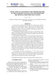
1. INTRODUCTION<br />
Curved face width spur gears, with variable<br />
tooth height along the gear face width [1] are<br />
especially <strong>de</strong>signed for plastic gears in or<strong>de</strong>r to<br />
increase their transmissible power level. The<br />
advantages of these gears, compared to standard<br />
spur gears are:<br />
- higher contact ratio for a given size of gear and<br />
number of teeth;<br />
- lower bending and contact stresses;<br />
- better meshing in plane misalignment conditions;<br />
- no axial forces as are inherent in helical gears and<br />
- enhanced lubrication un<strong>de</strong>r operating conditions.<br />
Against these advantages there are limitations:<br />
- the difficulty in gear <strong>de</strong>sign due to the complex<br />
tooth geometry compared to conventional <strong>de</strong>signs;<br />
- the difficulty in gear train mounting;<br />
- the sensitivity to center distance variations;<br />
- the manufacture is limited to cutting processes, as<br />
<strong>de</strong>signing a moulding die is almost impossible.<br />
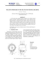
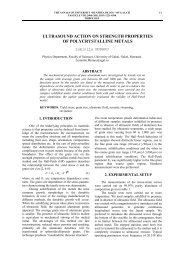
Experimental tests carried out by the authors on<br />
the running curved face width spur gears, with<br />
modified geometry, pointed out the peculiar thermal<br />
behaviour of the non-standard gears [2]. With these<br />
non-standard gears, running at high loads where<br />
conventional spur gears would fail, the gear surface<br />
temperature increased at an extremely high rate,<br />
recommending lubrication. It was obvious that the<br />
manufacturing process, leading to a rough flank<br />
surface, was the main cause for the high induced<br />
temperatures. Other influences on the friction forces<br />
generated should also be consi<strong>de</strong>red.<br />
It is well known that wear is the predominant<br />
mo<strong>de</strong> of failure for plastic gears, generally running<br />
with no lubrication. Over the traditional wear caused<br />
by the nonconformal tooth contact with both rolling<br />
and sliding components, plastic gears exhibit wear as<br />
a result of high friction and associated high<br />
temperatures [8]. Laws of Sliding Friction,<br />
consi<strong>de</strong>ring the <strong>de</strong>pen<strong>de</strong>nce of friction force on the<br />
normal load and its in<strong>de</strong>pen<strong>de</strong>nce on both the<br />
apparent area of contact and sliding velocity, are not<br />
obeyed by plastic materials. It was shown [12] that,<br />
once sliding is established in polymer/polymer<br />
contacts, the dynamic coefficient of friction is<br />
<strong>de</strong>pen<strong>de</strong>nt on sliding velocity and it is higher than the<br />
static coefficient of friction.<br />
This paper analyses the influence of the<br />
modified tooth geometry of the curved face width<br />
spur gears on the sliding velocity, as one of the main<br />
causes of frictional losses that increase the gear<br />
temperature above that of standard spur gears. The<br />
analysis also consi<strong>de</strong>rs the special meshing<br />
conditions of plastic gears: the low value of the<br />
material’s Young’s modulus results in high <strong>de</strong>flection<br />
of the meshing gear teeth and influences the sliding<br />
velocity due to changes in the point of contact.
12<br />
THE ANNALS <strong>OF</strong> UNIVERSITY “DUNĂREA DE JOS “ <strong>OF</strong> GALAŢI<br />
FASCICLE VIII, 2004, ISSN 1221-4590<br />
TRIBOLOGY<br />
2. CURVED FACE WIDTH<br />
SPUR GEARS WITH MODIFIED<br />
<strong>GEOMETRY</strong><br />
The curved face width gear geometry is produced<br />
using both the traditional conjugate surface generation<br />
theory [3] and solid mo<strong>de</strong>lling techniques [4]. The<br />
simulation of the non-standard gear generation, using<br />
solid mo<strong>de</strong>lling, was based on the following<br />
assumptions:<br />
- the virtual gear blank is a cylindrical primitive that<br />
is rotated about its axis and is provi<strong>de</strong>d with<br />
translation motion, tangential to the base circle of the<br />
gear, in or<strong>de</strong>r to get the rolling motion required for the<br />
involute tooth form generation;<br />
- the virtual tools, for the gear tooth concave and<br />
convex flank generations, are conical solid primitives<br />
that substitute the rotational motion of the imaginary<br />
rack-cutter flank, with zero pressure angle, about its<br />
inclined axis. The modified gear tooth geometry is<br />
<strong>de</strong>fined by the tool axis inclination β, and by the<br />
radius of the “generating circle”.<br />
Fig. 1. Tri-dimensional representation of curved face<br />
width spur gear teeth<br />
Figure 1 shows the representation of three<br />
generated teeth as solid mo<strong>de</strong>l. The tooth geometry,<br />
numerically i<strong>de</strong>ntified in several sections along the<br />
gear face width, is used for further investigations.<br />
3. THE THEORETICAL SLIDING<br />
VELOCITY<br />
The theory of gearing gives the following<br />
relation for the sliding velocity in gear pairs, with the<br />
standard involute tooth flank geometry (fig. 2):<br />
vs<br />
= ( ω1<br />
+ ω2<br />
) ⋅(<br />
PM )<br />
(1)<br />
where ω 1 and ω 2 are the angular velocities for pinion<br />
and gear respectively and (PM) is the distance<br />
between the pitch point P and the contact point M.<br />
If equation (1) is re-expressed as a function of<br />
θ 1 , the pinion roll angle - the in<strong>de</strong>pen<strong>de</strong>nt variable for<br />
the computer simulation, it becomes:<br />
R1<br />
⋅ sin θ1<br />
vs<br />
= ( ω1<br />
+ ω2<br />
) ⋅<br />
(2)<br />
cos( α w + θ1<br />
)<br />
where R 1 is the pinion pitch circle radius and α w - the<br />
pressure angle.<br />
pinion<br />
Rb2<br />
ω 2<br />
gear<br />
P M<br />
v s<br />
ω 1<br />
θ 1f<br />
θ<br />
1<br />
θ 1a<br />
R b1<br />
Fig. 2. Sliding velocity for a pair of teeth with the<br />
standard involute for tooth flank<br />
Due to the modified geometry of the nonstandard<br />
gears, the sliding velocity variation is<br />
modified along the gear face width. To analyse its<br />
variation it is assumed that the curved face width gear<br />
is ma<strong>de</strong> up by a stack of elementary standard spur<br />
gear sections. The calculation is <strong>de</strong>veloped in the<br />
particular case of a gear train with modulus 2 mm, 30<br />
teeth and 24 mm facewidth. Here two i<strong>de</strong>ntical gears<br />
are meshed together giving a gear ratio equal to one.<br />
The gear geometry is <strong>de</strong>fined by a tool axis<br />
inclination β = 5° and a radius R g = 24 mm. Each<br />
elementary gear section, with 2 mm facewidth,<br />
positioned by H i - the distance from the centre of the<br />
face width, has a particular geometry (table 1) whose<br />
parameters are i<strong>de</strong>ntified using the gear solid mo<strong>de</strong>l.<br />
Also, θ 1 varies, in every section H i , from θ 1a to θ 1f ,<br />
given by:<br />
2 2<br />
A sin α wi − Ra<br />
− Rbi<br />
θ1a<br />
= α wi − arctg<br />
Rbi<br />
Rbi<br />
θ1 f = arccos − α wi<br />
Ra<br />
(3)<br />
where A is the center distance and R a – the radius of<br />
the ad<strong>de</strong>ndum circle, constant for all the elementary<br />
spur gear sections.<br />
Section H i<br />
[mm]<br />
R f<br />
Table 1. Gear section geometry<br />
R b α w<br />
[mm] [°]<br />
[mm]<br />
0 27.5 28.19 20<br />
2 27.51 28.20 19.95<br />
4 27.53 28.22 19.84<br />
6 27.56 28.27 19.55<br />
8 27.64 28.34 19.15<br />
10 27.68 28.46 18.44<br />
12 27.77 28.65 17.25<br />
Figures 3 – 6 show the variation of the sliding<br />
velocity for several sections along the gear face<br />
width. Section 0 (fig. 3) has the standard involute for<br />
the gear tooth flank geometry leading to maximum
THE ANNALS <strong>OF</strong> UNIVERSITY “DUNĂREA DE JOS “ <strong>OF</strong> GALAŢI<br />
FASCICLE VIII, 2004, ISSN 1221-4590<br />
TRIBOLOGY<br />
13<br />
sliding velocity, as known, at the first and last points<br />
of contact. It may be seen that in other sections (fig.<br />
4-6) the maximum velocity is gradually increased,<br />
reflecting the increase of the length of the line of<br />
action due to the increase in gear base circle radius.<br />
Section 3, corresponding to the end of the gear<br />
face width, with a base circle radius with 1.6% higher<br />
than the standard value of the consi<strong>de</strong>red geometry,<br />
has an increase of 10% for the maximum sliding<br />
velocity. The sliding velocity is calculated for a speed<br />
of 1000 revs/min.<br />
in section 2 (H 2 = 8 mm)<br />
Fig. 6. The sliding velocity variation<br />
in section 3 (H 3 = 12 mm)<br />
Fig. 3. The sliding velocity variation<br />
in section 0 (H 0 = 0 mm)<br />
Fig. 4. The sliding velocity variation<br />
in section 1 (H 1 = 4 mm)<br />
Fig. 5. The sliding velocity variation<br />
Block [5] was the first who <strong>de</strong>termined the<br />
influence of relative sliding velocity on the flash<br />
temperature between sliding gear tooth surfaces:<br />
0.5<br />
ϕ f = F(<br />
k, ρ,c,w,b,dH ) ⋅v (4)<br />
s<br />
where F expresses the <strong>de</strong>pen<strong>de</strong>nce of flash<br />
temperature (ϕ f ) on the thermal conductivity (k),<br />
<strong>de</strong>nsity (ρ), specific heat (c) of the surfaces, Hertzian<br />
contact length (w), gear facewidth (b) and the<br />
instantaneous energy loss due to friction (dH).<br />
The analysis on curve face width gear geometry<br />
related to the sliding velocity variation, for the above<br />
mentioned dimensional parameters, shows that:<br />
- as the gear tooth height gradually <strong>de</strong>creases; the<br />
maximum reduction is about 6%;<br />
- the maximum sliding velocity gradually increases;<br />
at the end of the gear face width its value is higher<br />
with 10% than the standard value recor<strong>de</strong>d for the<br />
gear centre section;<br />
- the increase in sliding velocity leads to an increase<br />
of 4.8% for the gear’s flash temperature, one of the<br />
components of the maximum gear surface<br />
temperature [8].<br />
4. MESHING CONDITIONS <strong>OF</strong><br />
LOADED PLASTIC GEARS<br />
Polymer gear teeth, with a relatively low<br />
Young’s modulus, will <strong>de</strong>flect elastically un<strong>de</strong>r load,<br />
the <strong>de</strong>flections being larger than those experienced by<br />
metal gears. As a result of the applied load, a<br />
premature engagement takes place, as well as a<br />
<strong>de</strong>layed disengagement. Hence, the contact point for<br />
a plastic gear train is differently positioned compared<br />
to the i<strong>de</strong>al rigid gear pair and is influenced by the<br />
amount of tooth <strong>de</strong>flection.<br />
Gear tooth <strong>de</strong>flections were first calculated by<br />
Timoshenko and Bread [11] and the analysis has been<br />
refined since the original work by many workers.<br />
There are three kinds of <strong>de</strong>flection to be consi<strong>de</strong>red:<br />
<strong>de</strong>flection due to the local surface Hertzian<br />
compression and bending and shear <strong>de</strong>flections.
14<br />
THE ANNALS <strong>OF</strong> UNIVERSITY “DUNĂREA DE JOS “ <strong>OF</strong> GALAŢI<br />
FASCICLE VIII, 2004, ISSN 1221-4590<br />
TRIBOLOGY<br />
4.1. Influence of Hertzian <strong>de</strong>flection on<br />
sliding velocity<br />
The Hertzian compression, as an effect of<br />
tooth’s load, modifies the flank geometry, changing<br />
the standard involute into a straight line [10].<br />
Following Weber’s analysis [13], the real contact<br />
point extends down to the pressure line by an amount<br />
2δ H :<br />
M t<br />
2δ H =<br />
(5)<br />
2 ⋅ Rb<br />
⋅ k H<br />
where M t is the transmitted torque and k H – the<br />
stiffness of Hertzian contact. According to Hertzian<br />
law and assuming that the gear tooth surfaces are two<br />
cylin<strong>de</strong>r of diameters d 1 ’ and d 2 ’ respectively, the<br />
stiffness is given by:<br />
π⋅ E ⋅b<br />
k H =<br />
(6)<br />
' '<br />
2 2 2d1<br />
2d 2<br />
4(1 − ν ) ⋅(<br />
+ ln + ln )<br />
3 s s<br />
where E and ν are the Young’s modulus and<br />
Poisson’s ratio, s – the width of rectangular contact<br />
area. From the results <strong>de</strong>rived by Yang [14] the<br />
stiffness k H is practically a constant along the entire<br />
line of action and it can be calculated by the relation:<br />
π⋅ E ⋅b<br />
k H =<br />
2<br />
(6’)<br />
4(1 − ν )<br />
So, the <strong>de</strong>flection due to Hertzian contact is<br />
constant and in<strong>de</strong>pen<strong>de</strong>nt to the position of contact<br />
point. It increases the sliding velocity by an amount:<br />
H<br />
∆ vs = ( ω1<br />
+ ω2<br />
) ⋅ 2δ<br />
(7)<br />
H<br />
4.2. Influence of bending <strong>de</strong>flection on<br />
sliding velocity<br />
Bending <strong>de</strong>flection is calculated assuming that<br />
the tooth is a beam based on a rigid foundation. For<br />
the standard involute flank geometry, the contact<br />
force, exerted during gear meshing, is along the line<br />
of action. In the case of plastic gears, the variation of<br />
tooth profile <strong>de</strong>termines contacts in points that do not<br />
belong to the theoretical line of action and, therefore,<br />
the actions of the contact force are in unknown<br />
directions. But, since the contact points are in the<br />
vicinity of pressure line and, furthermore, they have<br />
the same sliding velocity as the point being on the<br />
same flank and on the line of action, the study on<br />
bending <strong>de</strong>flection can be <strong>de</strong>veloped, with small<br />
errors, consi<strong>de</strong>ring standard conditions.<br />
The displacement of the point where the load is<br />
applied has a bending and a shear component. Using<br />
Walton’s assumptions and calculation [9], the<br />
<strong>de</strong>flection due to both bending and shear is expressed<br />
as follow:<br />
- bending <strong>de</strong>flection:<br />
32M t 3<br />
b =<br />
⋅ h<br />
3 3 j<br />
π ⋅b<br />
⋅ E ⋅ m ⋅ Rb<br />
δ (8)<br />
where h j is the current tooth height, measured from<br />
the <strong>de</strong>d<strong>de</strong>ndum circle to the contact point. The<br />
increase in sliding velocity, due to bending<br />
<strong>de</strong>flection, varies along the gear tooth flank with:<br />
b<br />
∆ vs = ( ω1<br />
+ ω2<br />
) ⋅δb<br />
(9)<br />
- shear <strong>de</strong>flection:<br />
2M t<br />
δ sh =<br />
π⋅b<br />
⋅G<br />
⋅ m ⋅ R<br />
⋅ h j<br />
(10)<br />
where G is the shear modulus. The increase in sliding<br />
velocity, due to shear <strong>de</strong>flection, varies along the gear<br />
tooth flank with:<br />
sh<br />
∆ v = ( ω + ω ⋅δ<br />
(11)<br />
s 1 2 )<br />
5. THE REAL SLIDING VELOCITY<br />
Taking into account the total <strong>de</strong>flection of the<br />
plastic gear tooth, the real sliding velocity should be<br />
calculated as:<br />
r<br />
H b sh<br />
vs<br />
= vs<br />
+ ∆vs<br />
+ ∆vs<br />
+ ∆v<br />
(12)<br />
s<br />
To analyse both the influence of the nonstandard<br />
geometry and the influence of the low<br />
stiffness of the plastic gear tooth on the sliding<br />
velocity, the curved face width gear with the<br />
geometrical parameters mentioned in paragraph 3, is<br />
treated as a series of n standard spur gears. It is<br />
assumed that the transmitted torque is equally<br />
distributed on the elementary spur gears, with<br />
specific geometry. The gear is ma<strong>de</strong> by ERTALON<br />
66SA with E = 3450MPa, G = 1320 MPa and ν = 0.3.<br />
Using equations 5 -11 it was found that:<br />
- the Hertzian <strong>de</strong>flection is not significant and it can<br />
be ignored. Along the gear face width, the i<strong>de</strong>al<br />
sliding velocity is increased by 0.12 ÷ 0.1%; the<br />
maximum influence is recor<strong>de</strong>d at the gear’s centre,<br />
where the gear tooth flank has the standard involute,<br />
and is <strong>de</strong>creasing towards the gear face width ends<br />
due to the increase in base circle radius;<br />
- the shear <strong>de</strong>flection is also not important on the<br />
sliding velocity. The maximum increase of 0.86% is<br />
recor<strong>de</strong>d at the gear centre and is <strong>de</strong>creasing along<br />
the gear face width to a minimum value of 0.73% at<br />
the gear end sections;<br />
- the bending <strong>de</strong>flection is one of the components of<br />
gear tooth <strong>de</strong>flection that also <strong>de</strong>creases along the<br />
gear face width, a consequence of the higher gear<br />
tooth rigidity. The sliding velocity varies by 2.5÷<br />
1.8% from its i<strong>de</strong>al value due to bending <strong>de</strong>flection.<br />
Figure 7 shows the variation of the maximum<br />
sliding velocity (at speed of 1000 revs/min) at points<br />
the gears come out of mesh, where the bending<br />
<strong>de</strong>flection is maximum. It can be seen that the real<br />
sliding velocity, compared to its i<strong>de</strong>al value, varies<br />
from 3.5% at the gear half face width to 2.67% at the<br />
gear ends.<br />
b<br />
sh
THE ANNALS <strong>OF</strong> UNIVERSITY “DUNĂREA DE JOS “ <strong>OF</strong> GALAŢI<br />
FASCICLE VIII, 2004, ISSN 1221-4590<br />
TRIBOLOGY<br />
15<br />
of action length. At 16 mm radius of the tooth<br />
curvature, the increase of the sliding velocity is about<br />
26% from its standard value, <strong>de</strong>creasing to a 7%<br />
variation for R g = 28 mm. A further increase in<br />
generating circle radius gets the non-standard gear<br />
close to the standard spur gear where the maximum<br />
sliding velocity tends to its standard value.<br />
Fig. 7. The real sliding velocity variation<br />
Table 2<br />
Geometry of the non-standard gears (β = 5°)<br />
R g [mm] 16 20 24 28<br />
R b [mm] 29.17 28.82 28.65 28.55<br />
R f [mm] 27.94 27.83 27.77 27.7<br />
α w [°] 13.5 16.12 17.25 17.9<br />
Table 3<br />
Geometry of the non-standard gears (R b = 28mm)<br />
β [°] 2 5 8<br />
R b [mm] 28.41 28.55 28.69<br />
R f [mm] 27.65 27.7 27.78<br />
α w [°] 18.74 17.9 17<br />
A further study is <strong>de</strong>veloped consi<strong>de</strong>ring the<br />
influence of the curved face width gear geometry on<br />
the real sliding velocity. The non-standard gear<br />
geometry is <strong>de</strong>termined by two in<strong>de</strong>pen<strong>de</strong>nt parameters:<br />
the radius of the generating circle (R g ) and the<br />
tool axis inclination (β). It should be specified that<br />
the variation of these parameters is limited by both<br />
the gear face width and by the variation of the tooth<br />
height which may reduce the gear backlash. The solid<br />
mo<strong>de</strong>lling enabled the gear geometries to be<br />
produced and sections along the gear face width to be<br />
numerically <strong>de</strong>scribed (tables 2-3).<br />
As a first step, the tool axis inclination is<br />
<strong>de</strong>fined by β = 5° and the radius of the generating<br />
radius is incrementally increased from 16 to 28 mm.<br />
Table 1 presents the gear geometry at the end of the<br />
gear face width where the gear generation provi<strong>de</strong>s<br />
the maximum modification of the gear standard<br />
parameters.<br />
Figure 8 shows the variations of both i<strong>de</strong>al and<br />
real sliding velocities, at a speed of 1000 revs/min,<br />
along half of the gear face width, for several nonstandard<br />
gears, with different tooth curvature along<br />
the gear face width.<br />
It can be seen that the smaller the generating<br />
circle radius is, the higher is the increase in the i<strong>de</strong>al<br />
sliding velocity at the gear face width ends. This is<br />
explained by the low value of the pressure angle and<br />
the increase in base circle radius, modifying the line<br />
Fig. 8. Sliding velocity versus tooth curvature<br />
(β = 5°)<br />
Fig. 9. Sliding velocity versus tool axis inclination<br />
(R g = 28 mm)<br />
As regards to the real sliding velocity, this is<br />
also <strong>de</strong>creasing with an increase in the generating<br />
circle radius, with a lower rate than the i<strong>de</strong>al velocity.<br />
The maximum variation for the real sliding velocity,<br />
recor<strong>de</strong>d at the end of the gear face width ends is<br />
about 24% from the value calculated at the gear<br />
centre, and <strong>de</strong>creases to around 6.5% for R g = 28 mm.<br />
If the generating circle radius is increased, the gear<br />
tooth is more flexible and leads to an increase in<br />
velocity variation. Compared to its i<strong>de</strong>al counterpart,<br />
the real sliding velocity is higher by 2% for R g = 16<br />
mm and by 3% for R g = 28 mm, respectively. This
16<br />
THE ANNALS <strong>OF</strong> UNIVERSITY “DUNĂREA DE JOS “ <strong>OF</strong> GALAŢI<br />
FASCICLE VIII, 2004, ISSN 1221-4590<br />
TRIBOLOGY<br />
means that the tooth <strong>de</strong>flection has a reduced<br />
influence on gear sliding velocity.<br />
Table 3 presents the curved face width gear<br />
geometry, at the gear face width end, <strong>de</strong>fined by R g =<br />
28 mm and several tool axis inclinations. Figure 9<br />
shows the variations of the i<strong>de</strong>al and real sliding<br />
velocity along half of the gear face width. It can be<br />
seen that the i<strong>de</strong>al velocity varies, along the gear face<br />
width, by 4.2% (β = 2°) to 10.7% (β = 8°). The real<br />
sliding velocity variation is about 3.8% (β = 2°) and<br />
9.8% (β = 8°).<br />
The data show that the plastic non-standard gear<br />
sliding velocity is affected by the in<strong>de</strong>pen<strong>de</strong>nt<br />
parameters that control gear geometry as follows:<br />
- an increase in generating circle radius reduces both<br />
the i<strong>de</strong>al and the real sliding velocity variation;<br />
- an increase in tool axis inclination increases the<br />
sliding velocity variation.<br />
The variable tooth stiffness reduces the variation<br />
of the real sliding velocity compared to the i<strong>de</strong>al<br />
velocity, due to the <strong>de</strong>crease in tooth <strong>de</strong>flection from<br />
the gear centre to its end sections.<br />
6. CONCLUSIONS<br />
An analysis on sliding velocity is <strong>de</strong>veloped<br />
for the case of a plastic curved face width gear train,<br />
with modified geometry, as the sliding velocity has a<br />
direct influence on the gear flash temperature<br />
generated. Experimental investigations on the thermal<br />
behaviour of non-standard curved face width gears<br />
showed that high temperatures were induced.<br />
There are two peculiarities of these gears,<br />
which required investigation as they influence the<br />
variation in sliding velocity:<br />
1. the gear geometry that is <strong>de</strong>pen<strong>de</strong>nt on the gear<br />
generating process, by the radius of the tool<br />
“generating point”, that is provi<strong>de</strong>d with rotational<br />
motion, as well as by the tool inclination axis;<br />
2. the lower material stiffness that affects gear<br />
meshing conditions;<br />
The i<strong>de</strong>al sliding velocity is calculated using the<br />
traditional practice for metal gears and consi<strong>de</strong>rs the<br />
influence of the gear geometry on its variation. As a<br />
consequence of the base circle radius and pressure<br />
angle variations, along the gear face width, the line of<br />
action has an increased length and the maximum<br />
sliding velocity is higher towards the gear face width<br />
end sections.<br />
The real sliding velocity consi<strong>de</strong>rs the influence<br />
of both the gear geometry and tooth <strong>de</strong>flection. It was<br />
found out that the sliding velocity is mainly<br />
influenced by the gear geometry. The gear tooth<br />
<strong>de</strong>flections do not have a significant influence on the<br />
sliding velocity - they reduced its variation compared<br />
to the i<strong>de</strong>al calculation.<br />
REFERENCES<br />
1. Andrei L., 2002, Study of plastic curved face-width spur gear<br />
generation and behaviour, PhD Thesis, University “<strong>Dunarea</strong> <strong>de</strong><br />
<strong>Jos</strong>” of Galati.<br />
2. Andrei L., Epureanu Al., Andrei G., Walton D., 2004,<br />
Investigation of the Thermal Behaviour of Non-metallic Curved-<br />
Face-Width Spur Gears, Tribotest Journal 10-4, Leaf Coppin, p.<br />
299-310.<br />
3. Andrei L., Andrei G., Epureanu Al., Oancea N., Walton D.,<br />
2002, Numerical simulation and generation of curved face width<br />
gears, Int. J. Machine Tools Manufact., 42, p. 1-6.<br />
4. Andrei L., Andrei G., Mereuta E., 2002, Simulation of<br />
curved-face-width spur gear generation and mesh using the solid<br />
mo<strong>de</strong>lling method, Proc. 10 th Int. Conf. on Geometry and<br />
Graphics, Kiev, Ucraine, Vol.1, p. 245-9.<br />
5. Block H., 1933, Les Temperatures <strong>de</strong> Surface dans les<br />
Conditions <strong>de</strong> fraissage sous Pressions Extreme, Congr.<br />
Mondialopetr. Le 2 Congr., Paris, 47—486.<br />
6. Davoli P., Gorla C., 1996, Meshing Conditions of Loa<strong>de</strong>d<br />
Plastic Gears: Numerical Analysis and Experimental tests, Berichte<br />
no 1230, p. 383-396.<br />
7. Goodwin A. J., 1994, The wear of dry running steel gears,<br />
Mphil thesis, The University of Birmingham, UK.<br />
8. Hooke C.J., Mao K., et al, 1992, Measurement and Prediction<br />
of the Surface Temperature in Polymer Gears and Its Relationship<br />
to Gear Wear, J. Tribology (trans. ASME)-12, p. 1-6.<br />
9. Meuleman P. K., Walton D., Weale D. J., Driessen I., 2000,<br />
Minimisation of transmission errors in highly loa<strong>de</strong>d plastic gears.<br />
Research done un<strong>de</strong>r the European Industrial and Materials<br />
Programme (Brite EuRam III), Mid-term report, Project No BE97-<br />
4752.<br />
10. Nikas G.K., 1996, Load Sharing and Profile Modification of<br />
Spur Gear Teeth in the General Case of any Flank Geometry,<br />
Berichte no 1230, p. 923-935.<br />
11. Timoshenko S., Braud R.V., 1926, Strength of gear teeth is<br />
greatly affected by fillet radius, Automotive Industries, p. 138-142.<br />
12. Walton D., Cropper A.B. Weale D.J., Meuleman P. K.,<br />
2002, The efficiency and friction of plastic cylindrical gears: Part 1<br />
– influence of materials, Proc. IMechE, Part J: Journal of<br />
Engineering Tribology, vol. 216, p. 75-92.<br />
13. Weber C., 1949, The <strong>de</strong>formation of loa<strong>de</strong>d gears and the<br />
effect of their load carrying capacity, British Scientific and<br />
Industrial Research, Sponsored Research (Germany), Report No 3.<br />
14. Yang D.C., Lin I.Y., 1987, Hertzian Damping, Tooth Friction<br />
and Bending Elasticity in Gear Impact Dynamics, J. Mechanical<br />
Transmission and Automation in Design, vol. 109.