INFLUENCE OF A NON-STANDARD GEOMETRY ... - Dunarea de Jos
INFLUENCE OF A NON-STANDARD GEOMETRY ... - Dunarea de Jos
INFLUENCE OF A NON-STANDARD GEOMETRY ... - Dunarea de Jos
You also want an ePaper? Increase the reach of your titles
YUMPU automatically turns print PDFs into web optimized ePapers that Google loves.
14<br />
THE ANNALS <strong>OF</strong> UNIVERSITY “DUNĂREA DE JOS “ <strong>OF</strong> GALAŢI<br />
FASCICLE VIII, 2004, ISSN 1221-4590<br />
TRIBOLOGY<br />
4.1. Influence of Hertzian <strong>de</strong>flection on<br />
sliding velocity<br />
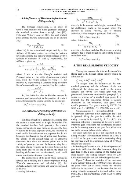
The Hertzian compression, as an effect of<br />
tooth’s load, modifies the flank geometry, changing<br />
the standard involute into a straight line [10].<br />
Following Weber’s analysis [13], the real contact<br />
point extends down to the pressure line by an amount<br />
2δ H :<br />
M t<br />
2δ H =<br />
(5)<br />
2 ⋅ Rb<br />
⋅ k H<br />
where M t is the transmitted torque and k H – the<br />
stiffness of Hertzian contact. According to Hertzian<br />
law and assuming that the gear tooth surfaces are two<br />
cylin<strong>de</strong>r of diameters d 1 ’ and d 2 ’ respectively, the<br />
stiffness is given by:<br />
π⋅ E ⋅b<br />
k H =<br />
(6)<br />
' '<br />
2 2 2d1<br />
2d 2<br />
4(1 − ν ) ⋅(<br />
+ ln + ln )<br />
3 s s<br />
where E and ν are the Young’s modulus and<br />
Poisson’s ratio, s – the width of rectangular contact<br />
area. From the results <strong>de</strong>rived by Yang [14] the<br />
stiffness k H is practically a constant along the entire<br />
line of action and it can be calculated by the relation:<br />
π⋅ E ⋅b<br />
k H =<br />
2<br />
(6’)<br />
4(1 − ν )<br />
So, the <strong>de</strong>flection due to Hertzian contact is<br />
constant and in<strong>de</strong>pen<strong>de</strong>nt to the position of contact<br />
point. It increases the sliding velocity by an amount:<br />
H<br />
∆ vs = ( ω1<br />
+ ω2<br />
) ⋅ 2δ<br />
(7)<br />
H<br />
4.2. Influence of bending <strong>de</strong>flection on<br />
sliding velocity<br />
Bending <strong>de</strong>flection is calculated assuming that<br />
the tooth is a beam based on a rigid foundation. For<br />
the standard involute flank geometry, the contact<br />
force, exerted during gear meshing, is along the line<br />
of action. In the case of plastic gears, the variation of<br />
tooth profile <strong>de</strong>termines contacts in points that do not<br />
belong to the theoretical line of action and, therefore,<br />
the actions of the contact force are in unknown<br />
directions. But, since the contact points are in the<br />
vicinity of pressure line and, furthermore, they have<br />
the same sliding velocity as the point being on the<br />
same flank and on the line of action, the study on<br />
bending <strong>de</strong>flection can be <strong>de</strong>veloped, with small<br />
errors, consi<strong>de</strong>ring standard conditions.<br />
The displacement of the point where the load is<br />
applied has a bending and a shear component. Using<br />
Walton’s assumptions and calculation [9], the<br />
<strong>de</strong>flection due to both bending and shear is expressed<br />
as follow:<br />
- bending <strong>de</strong>flection:<br />
32M t 3<br />
b =<br />
⋅ h<br />
3 3 j<br />
π ⋅b<br />
⋅ E ⋅ m ⋅ Rb<br />
δ (8)<br />
where h j is the current tooth height, measured from<br />
the <strong>de</strong>d<strong>de</strong>ndum circle to the contact point. The<br />
increase in sliding velocity, due to bending<br />
<strong>de</strong>flection, varies along the gear tooth flank with:<br />
b<br />
∆ vs = ( ω1<br />
+ ω2<br />
) ⋅δb<br />
(9)<br />
- shear <strong>de</strong>flection:<br />
2M t<br />
δ sh =<br />
π⋅b<br />
⋅G<br />
⋅ m ⋅ R<br />
⋅ h j<br />
(10)<br />
where G is the shear modulus. The increase in sliding<br />
velocity, due to shear <strong>de</strong>flection, varies along the gear<br />
tooth flank with:<br />
sh<br />
∆ v = ( ω + ω ⋅δ<br />
(11)<br />
s 1 2 )<br />
5. THE REAL SLIDING VELOCITY<br />
Taking into account the total <strong>de</strong>flection of the<br />
plastic gear tooth, the real sliding velocity should be<br />
calculated as:<br />
r<br />
H b sh<br />
vs<br />
= vs<br />
+ ∆vs<br />
+ ∆vs<br />
+ ∆v<br />
(12)<br />
s<br />
To analyse both the influence of the nonstandard<br />
geometry and the influence of the low<br />
stiffness of the plastic gear tooth on the sliding<br />
velocity, the curved face width gear with the<br />
geometrical parameters mentioned in paragraph 3, is<br />
treated as a series of n standard spur gears. It is<br />
assumed that the transmitted torque is equally<br />
distributed on the elementary spur gears, with<br />
specific geometry. The gear is ma<strong>de</strong> by ERTALON<br />
66SA with E = 3450MPa, G = 1320 MPa and ν = 0.3.<br />
Using equations 5 -11 it was found that:<br />
- the Hertzian <strong>de</strong>flection is not significant and it can<br />
be ignored. Along the gear face width, the i<strong>de</strong>al<br />
sliding velocity is increased by 0.12 ÷ 0.1%; the<br />
maximum influence is recor<strong>de</strong>d at the gear’s centre,<br />
where the gear tooth flank has the standard involute,<br />
and is <strong>de</strong>creasing towards the gear face width ends<br />
due to the increase in base circle radius;<br />
- the shear <strong>de</strong>flection is also not important on the<br />
sliding velocity. The maximum increase of 0.86% is<br />
recor<strong>de</strong>d at the gear centre and is <strong>de</strong>creasing along<br />
the gear face width to a minimum value of 0.73% at<br />
the gear end sections;<br />
- the bending <strong>de</strong>flection is one of the components of<br />
gear tooth <strong>de</strong>flection that also <strong>de</strong>creases along the<br />
gear face width, a consequence of the higher gear<br />
tooth rigidity. The sliding velocity varies by 2.5÷<br />
1.8% from its i<strong>de</strong>al value due to bending <strong>de</strong>flection.<br />
Figure 7 shows the variation of the maximum<br />
sliding velocity (at speed of 1000 revs/min) at points<br />
the gears come out of mesh, where the bending<br />
<strong>de</strong>flection is maximum. It can be seen that the real<br />
sliding velocity, compared to its i<strong>de</strong>al value, varies<br />
from 3.5% at the gear half face width to 2.67% at the<br />
gear ends.<br />
b<br />
sh


