INFLUENCE OF A NON-STANDARD GEOMETRY ... - Dunarea de Jos
INFLUENCE OF A NON-STANDARD GEOMETRY ... - Dunarea de Jos
INFLUENCE OF A NON-STANDARD GEOMETRY ... - Dunarea de Jos

Create successful ePaper yourself
Turn your PDF publications into a flip-book with our unique Google optimized e-Paper software.
12<br />
THE ANNALS <strong>OF</strong> UNIVERSITY “DUNĂREA DE JOS “ <strong>OF</strong> GALAŢI<br />
FASCICLE VIII, 2004, ISSN 1221-4590<br />
TRIBOLOGY<br />
2. CURVED FACE WIDTH<br />
SPUR GEARS WITH MODIFIED<br />
<strong>GEOMETRY</strong><br />
The curved face width gear geometry is produced<br />
using both the traditional conjugate surface generation<br />
theory [3] and solid mo<strong>de</strong>lling techniques [4]. The<br />
simulation of the non-standard gear generation, using<br />
solid mo<strong>de</strong>lling, was based on the following<br />
assumptions:<br />
- the virtual gear blank is a cylindrical primitive that<br />
is rotated about its axis and is provi<strong>de</strong>d with<br />
translation motion, tangential to the base circle of the<br />
gear, in or<strong>de</strong>r to get the rolling motion required for the<br />
involute tooth form generation;<br />
- the virtual tools, for the gear tooth concave and<br />
convex flank generations, are conical solid primitives<br />
that substitute the rotational motion of the imaginary<br />
rack-cutter flank, with zero pressure angle, about its<br />
inclined axis. The modified gear tooth geometry is<br />
<strong>de</strong>fined by the tool axis inclination β, and by the<br />
radius of the “generating circle”.<br />
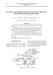
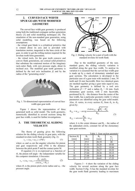
Fig. 1. Tri-dimensional representation of curved face<br />
width spur gear teeth<br />
Figure 1 shows the representation of three<br />
generated teeth as solid mo<strong>de</strong>l. The tooth geometry,<br />
numerically i<strong>de</strong>ntified in several sections along the<br />
gear face width, is used for further investigations.<br />
3. THE THEORETICAL SLIDING<br />
VELOCITY<br />
The theory of gearing gives the following<br />
relation for the sliding velocity in gear pairs, with the<br />
standard involute tooth flank geometry (fig. 2):<br />
vs<br />
= ( ω1<br />
+ ω2<br />
) ⋅(<br />
PM )<br />
(1)<br />
where ω 1 and ω 2 are the angular velocities for pinion<br />
and gear respectively and (PM) is the distance<br />
between the pitch point P and the contact point M.<br />
If equation (1) is re-expressed as a function of<br />
θ 1 , the pinion roll angle - the in<strong>de</strong>pen<strong>de</strong>nt variable for<br />
the computer simulation, it becomes:<br />
R1<br />
⋅ sin θ1<br />
vs<br />
= ( ω1<br />
+ ω2<br />
) ⋅<br />
(2)<br />
cos( α w + θ1<br />
)<br />
where R 1 is the pinion pitch circle radius and α w - the<br />
pressure angle.<br />
pinion<br />
Rb2<br />
ω 2<br />
gear<br />
P M<br />
v s<br />
ω 1<br />
θ 1f<br />
θ<br />
1<br />
θ 1a<br />
R b1<br />
Fig. 2. Sliding velocity for a pair of teeth with the<br />
standard involute for tooth flank<br />
Due to the modified geometry of the nonstandard<br />
gears, the sliding velocity variation is<br />
modified along the gear face width. To analyse its<br />
variation it is assumed that the curved face width gear<br />
is ma<strong>de</strong> up by a stack of elementary standard spur<br />
gear sections. The calculation is <strong>de</strong>veloped in the<br />
particular case of a gear train with modulus 2 mm, 30<br />
teeth and 24 mm facewidth. Here two i<strong>de</strong>ntical gears<br />
are meshed together giving a gear ratio equal to one.<br />
The gear geometry is <strong>de</strong>fined by a tool axis<br />
inclination β = 5° and a radius R g = 24 mm. Each<br />
elementary gear section, with 2 mm facewidth,<br />
positioned by H i - the distance from the centre of the<br />
face width, has a particular geometry (table 1) whose<br />
parameters are i<strong>de</strong>ntified using the gear solid mo<strong>de</strong>l.<br />
Also, θ 1 varies, in every section H i , from θ 1a to θ 1f ,<br />
given by:<br />
2 2<br />
A sin α wi − Ra<br />
− Rbi<br />
θ1a<br />
= α wi − arctg<br />
Rbi<br />
Rbi<br />
θ1 f = arccos − α wi<br />
Ra<br />
(3)<br />
where A is the center distance and R a – the radius of<br />
the ad<strong>de</strong>ndum circle, constant for all the elementary<br />
spur gear sections.<br />
Section H i<br />
[mm]<br />
R f<br />
Table 1. Gear section geometry<br />
R b α w<br />
[mm] [°]<br />
[mm]<br />
0 27.5 28.19 20<br />
2 27.51 28.20 19.95<br />
4 27.53 28.22 19.84<br />
6 27.56 28.27 19.55<br />
8 27.64 28.34 19.15<br />
10 27.68 28.46 18.44<br />
12 27.77 28.65 17.25<br />
Figures 3 – 6 show the variation of the sliding<br />
velocity for several sections along the gear face<br />
width. Section 0 (fig. 3) has the standard involute for<br />
the gear tooth flank geometry leading to maximum