DP7700 Series - Omega Engineering
DP7700 Series - Omega Engineering
DP7700 Series - Omega Engineering
Create successful ePaper yourself
Turn your PDF publications into a flip-book with our unique Google optimized e-Paper software.
User’s Guide<br />
Shop online at<br />
omega.com<br />
e-mail: info@omega.com<br />
For latest product manuals:<br />
omegamanual.info<br />
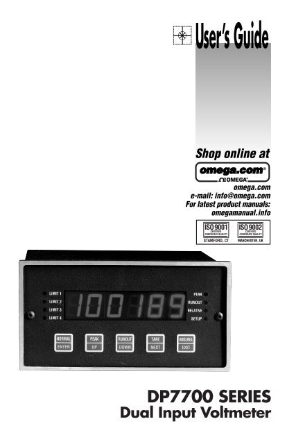
<strong>DP7700</strong> SERIES<br />
Dual Input Voltmeter
OMEGAnet ® Online Service<br />
omega.com<br />
Internet e-mail<br />
info@omega.com<br />
Servicing North America:<br />
USA: One <strong>Omega</strong> Drive, Box 4047<br />
ISO 9001 Certified Stamford CT 06907-0047<br />
Tel: (203) 359-1660 FAX: (203) 359-7700<br />
e-mail: info@omega.com<br />
Canada:<br />
976 Bergar<br />
Laval (Quebec) H7L 5A1, Canada<br />
Tel: (514) 856-6928 FAX: (514) 856-6886<br />
e-mail: info@omega.ca<br />
For immediate technical or application assistance:<br />
USA and Canada: Sales Service: 1-800-826-6342 / 1-800-TC-OMEGA ®<br />
Customer Service: 1-800-622-2378 / 1-800-622-BEST ®<br />
<strong>Engineering</strong> Service: 1-800-872-9436 / 1-800-USA-WHEN ®<br />
TELEX: 996404 EASYLINK: 62968934 CABLE: OMEGA<br />
Mexico: En Español: (001) 203-359-7803 e-mail: espanol@omega.com<br />
FAX: (001) 203-359-7807<br />
info@omega.com.mx<br />
Servicing Europe:<br />
Benelux:<br />
Postbus 8034, 1180 LA Amstelveen, The Netherlands<br />
Tel: +31 (0)20 3472121 FAX: +31 (0)20 6434643<br />
Toll Free in Benelux: 0800 0993344<br />
e-mail: sales@omegaeng.nl<br />
Czech Republic: Frystatska 184, 733 01 Karvina´, Czech Republic<br />
Tel: +420 (0)59 6311899 FAX: +420 (0)59 6311114<br />
Toll Free: 0800-1-66342<br />
e-mail: info@omegashop.cz<br />
France:<br />
11, rue Jacques Cartier, 78280 Guyancourt, France<br />
Tel: +33 (0)1 61 37 2900 FAX: +33 (0)1 30 57 5427<br />
Toll Free in France: 0800 466 342<br />
e-mail: sales@omega.fr<br />
Germany/Austria: Daimlerstrasse 26, D-75392 Deckenpfronn, Germany<br />
Tel: +49 (0)7056 9398-0 FAX: +49 (0)7056 9398-29<br />
Toll Free in Germany: 0800 639 7678<br />
e-mail: info@omega.de<br />
United Kingdom: One <strong>Omega</strong> Drive, River Bend Technology Centre<br />
ISO 9002 Certified Northbank, Irlam, Manchester<br />
M44 5BD United Kingdom<br />
Tel: +44 (0)161 777 6611 FAX: +44 (0)161 777 6622<br />
Toll Free in United Kingdom: 0800-488-488<br />
e-mail: sales@omega.co.uk<br />
It is the policy of OMEGA <strong>Engineering</strong>, Inc. to comply with all worldwide safety and EMC/EMI<br />
regulations that apply. OMEGA is constantly pursuing certification of its products to the European New<br />
Approach Directives. OMEGA will add the CE mark to every appropriate device upon certification.<br />
The information contained in this document is believed to be correct, but OMEGA accepts no liability for any<br />
errors it contains, and reserves the right to alter specifications without notice.<br />
WARNING: These products are not designed for use in, and should not be used for, human applications.
TABLE OF CONTENTS<br />
SPECIFICATIONS . . . . . . . . . . . . . . . . . . . . . . . . . . . . . . . . . . . . . . . . 1<br />
DESCRIPTION . . . . . . . . . . . . . . . . . . . . . . . . . . . . . . . . . . . . . . . . . . . 4<br />
SWITCH FUNCTIONS . . . . . . . . . . . . . . . . . . . . . . . . . . . . . . . . . . . . 4<br />
LED INDICATORS . . . . . . . . . . . . . . . . . . . . . . . . . . . . . . . . . . . . . . . 5<br />
SETUP . . . . . . . . . . . . . . . . . . . . . . . . . . . . . . . . . . . . . . . . . . . . . . . . . . 6<br />
Limit Programming. . . . . . . . . . . . . . . . . . . . . . . . . . . . . . . . . . . . . 7<br />
Limit One Delay . . . . . . . . . . . . . . . . . . . . . . . . . . . . . . . . . . . . . . . 7<br />
Decimal Point Position . . . . . . . . . . . . . . . . . . . . . . . . . . . . . . . . . . 8<br />
Filter Setup. . . . . . . . . . . . . . . . . . . . . . . . . . . . . . . . . . . . . . . . . . . . 8<br />
Baud Rate Selection. . . . . . . . . . . . . . . . . . . . . . . . . . . . . . . . . . . . . 8<br />
Echo Setup . . . . . . . . . . . . . . . . . . . . . . . . . . . . . . . . . . . . . . . . . . . . 8<br />
Linefeed Setup . . . . . . . . . . . . . . . . . . . . . . . . . . . . . . . . . . . . . . . . . 8<br />
Unit Address Setup . . . . . . . . . . . . . . . . . . . . . . . . . . . . . . . . . . . . . 8<br />
Legend Setup . . . . . . . . . . . . . . . . . . . . . . . . . . . . . . . . . . . . . . . . . . 8<br />
Continuous Update . . . . . . . . . . . . . . . . . . . . . . . . . . . . . . . . . . . . . 9<br />
Device Code . . . . . . . . . . . . . . . . . . . . . . . . . . . . . . . . . . . . . . . . . . 9<br />
Serial Command . . . . . . . . . . . . . . . . . . . . . . . . . . . . . . . . . . . . . . . 9<br />
CALIBRATION. . . . . . . . . . . . . . . . . . . . . . . . . . . . . . . . . . . . . . . . . . . 9<br />
Protection Code . . . . . . . . . . . . . . . . . . . . . . . . . . . . . . . . . . . . . . . 10<br />
Protection Code Programming. . . . . . . . . . . . . . . . . . . . . . . . . . . . 10<br />
Channel Selection Programming . . . . . . . . . . . . . . . . . . . . . . . . . . 10<br />
Span Number Programming . . . . . . . . . . . . . . . . . . . . . . . . . . . . . 10<br />
Dead Weight Zero . . . . . . . . . . . . . . . . . . . . . . . . . . . . . . . . . . . . . 10<br />
Dead Weight Stay . . . . . . . . . . . . . . . . . . . . . . . . . . . . . . . . . . . . . 10<br />
SERIAL COMMUNICATIONS . . . . . . . . . . . . . . . . . . . . . . . . . . . . . 11<br />
Echo . . . . . . . . . . . . . . . . . . . . . . . . . . . . . . . . . . . . . . . . . . . . . . . . 12<br />
Line Feed . . . . . . . . . . . . . . . . . . . . . . . . . . . . . . . . . . . . . . . . . . . . 13<br />
Address Enable . . . . . . . . . . . . . . . . . . . . . . . . . . . . . . . . . . . . . . . 13<br />
Address Disable . . . . . . . . . . . . . . . . . . . . . . . . . . . . . . . . . . . . . . . 13<br />
Read Display . . . . . . . . . . . . . . . . . . . . . . . . . . . . . . . . . . . . . . . . . 13<br />
Set Limit . . . . . . . . . . . . . . . . . . . . . . . . . . . . . . . . . . . . . . . . . . . . 13
TABLE OF CONTENT<br />
Peak and Runout . . . . . . . . . . . . . . . . . . . . . . . . . . . . . . . . . . . . . . 13<br />
Remote Tare. . . . . . . . . . . . . . . . . . . . . . . . . . . . . . . . . . . . . . . . . . 13<br />
Test Message . . . . . . . . . . . . . . . . . . . . . . . . . . . . . . . . . . . . . . . . . 14<br />
Continuous Reading. . . . . . . . . . . . . . . . . . . . . . . . . . . . . . . . . . . . 14<br />
Set Legend . . . . . . . . . . . . . . . . . . . . . . . . . . . . . . . . . . . . . . . . . . . 14<br />
Remote Serial Command. . . . . . . . . . . . . . . . . . . . . . . . . . . . . . . . 14<br />
Decimal Position . . . . . . . . . . . . . . . . . . . . . . . . . . . . . . . . . . . . . . 14<br />
Reading Mode . . . . . . . . . . . . . . . . . . . . . . . . . . . . . . . . . . . . . . . . 15<br />
Absolute or Relative . . . . . . . . . . . . . . . . . . . . . . . . . . . . . . . . . . . 15<br />
Set Filter. . . . . . . . . . . . . . . . . . . . . . . . . . . . . . . . . . . . . . . . . . . . . 15<br />
Calibration Span Number . . . . . . . . . . . . . . . . . . . . . . . . . . . . . . . 15<br />
Serial Reading Mode . . . . . . . . . . . . . . . . . . . . . . . . . . . . . . . . . . . 15<br />
Limit Mode . . . . . . . . . . . . . . . . . . . . . . . . . . . . . . . . . . . . . . . . . . 15<br />
REMOTE INPUTS . . . . . . . . . . . . . . . . . . . . . . . . . . . . . . . . . . . . . . 16<br />
INPUT CONNECTIONS . . . . . . . . . . . . . . . . . . . . . . . . . . . . . . . . . . 17<br />
<strong>DP7700</strong> BACK VIEW . . . . . . . . . . . . . . . . . . . . . . . . . . . . . . . . . . . . 17<br />
<strong>DP7700</strong> RANGE SETTINGS . . . . . . . . . . . . . . . . . . . . . . . . . . . . . . . 17<br />
<strong>DP7700</strong> REAR TERMINATIONS and HOOKUP. . . . . . . . . . . 18, 18a<br />
18b, 18c, 18d<br />
SCHEMATIC (<strong>DP7700</strong> Top Board) . . . . . . . . . . . . . . . . . . . . . . . . . . 19<br />
SCHEMATIC (<strong>DP7700</strong> Bottom Board) . . . . . . . . . . . . . . . . . . . . . . . 22<br />
SCHEMATIC (<strong>DP7700</strong> Analog Input Option Board) . . . . . . . . . . . . . 24<br />
SCHEMATIC (<strong>DP7700</strong> Output Option Board). . . . . . . . . . . . . . . . . . 25<br />
SCHEMATIC (<strong>DP7700</strong> RS232/RS485 Option Board) . . . . . . . . . . . . 26<br />
DIMENSIONS. . . . . . . . . . . . . . . . . . . . . . . . . . . . . . . . . . . . . . . . . . . 27<br />
MOUNTING & WARRANTY . . . . . . . . . . . . . . . . . . . . . . . . . . . . . . 28
SPECIFICATIONS<br />
Accuracy:<br />
• ±.01% of reading (1 counts of A/D @ 25°C. Temperature coefficient<br />
50ppm/degree Celsius.<br />
Display:<br />
• -32768 to +32767 with programmable decimal points.<br />
• .56” Red LED<br />
NMRR:<br />
• 70db<br />
A/D Converter:<br />
• 16 bits (65,536 counts) 1,000 reading per second maximum.<br />
Input Analog Filter:<br />
• 4 pole active anti-alias<br />
• 500Hz cutoff on single channel unit, 250Hz cutoff on dual channel unit.<br />
Rollover Error:<br />
• ±50 NA maximum, (100 pA/C (per input channel)<br />
Input Bias Current:<br />
• ±50 NA maximum, (1200pA/C (per input channel)<br />
Input Impedance:<br />
• Range Input Impedance<br />
±200mVDC 10 12 Ω<br />
±5VDC<br />
1MΩ<br />
±10VDC<br />
1MΩ<br />
4 - 20mA 10Ω<br />
Excitation:<br />
• ±15VDC, ±.5VDC @ 50mA<br />
Range Selection:<br />
• Selectable by DIP switch on rear of unit.<br />
Calibration:<br />
• Digital calibration via front panel switches<br />
• No potentiometer adjustments<br />
• Calibration switches can be disabled with access code to prevent<br />
unauthorized access to calibration parameters.<br />
1
Front Panel Controls:<br />
• Five push button switches for programming digital filter, offset, span, limits<br />
and recall of peak reading or run out from storage.<br />
Channels:<br />
• One channel standard with second channel optional.<br />
Reading Rate:<br />
• Limited to 1000 per second divided by number of channels.<br />
Digital Filter:<br />
• Programmable cutoff frequency 1Hz to 500Hz.<br />
• Display updates 3 time per second.<br />
Peak Detector:<br />
• Update at rate selected by digital filter. Peak is normally stored in memory<br />
and recalled via front panel switch, over the serial interface or by selecting<br />
peak detect display mode on rear connector. If peak display mode is selected<br />
an internal timer can be programmed to give limit #1 output up to 100<br />
seconds after a programmed limit is reached. This output can be used to<br />
reset the peak reading by tying limit #1 output to remote input.<br />
Run Out Mode:<br />
• Updated at rate selected by digital filter. Runout is normally stored in<br />
memory and recalled via front panel switch, over the serial interface, or by<br />
selecting runout display mode on rear connector. If runout display mode is<br />
selected an internal timer can be programmed to give Limit #1 output up to<br />
100 seconds after a programmed limit is reached. This output can be used to<br />
reset the runout reading by tying Limit #1 output to remote input.<br />
Analog Output:<br />
• 0 - 10VDC, 0 - 5VDC, 4 - 20mA, tracks display reading.<br />
• Voltage outputs will sink or source 1mA.<br />
• 300V isolation between analog outputs and instrument ground<br />
• 12 bit D/A converter updated at selected digital filter rate.<br />
Convert/Hold Input:<br />
• Normally high, if pulled low will hold display.<br />
• Requires 1 millisecond positive pulse for single conversion.<br />
Limit Outputs:<br />
• Four isolated open collector transistor outputs rated 30VDC maximum.<br />
• Will sink up to 50mA.<br />
• 300V isolation between limit outputs and system ground.<br />
• Limit #1 can be programmed to be delayed from 1 to 100 second in one second<br />
increments. Optional: Two form “A” relay contacts, rated 2.5 A @<br />
115VAC.<br />
2
• Isolated transistor outputs not available when relays are installed. Limit 1<br />
and Limit 2 activated the relay contacts.<br />
I/O Method:<br />
• Quick disconnect screw terminal block, RJ11 Jack for serial interface.<br />
Power:<br />
• 115/230VAC Selectable by switch on rear of unit.<br />
• 8 watts maximum<br />
• Optional 10-30VDC @ 600mA<br />
Remote Inputs:<br />
• Active low TTL compatible, 50 millisecond negative pulse required.<br />
• Tare<br />
• Display peak reading<br />
• Display run out.<br />
• Reset peak reading or run out reading.<br />
Operation Temperature Range:<br />
• -20°C to +60°C<br />
Serial Interface:<br />
• ASCII RS232 or RS485 compatible (optional).<br />
• 300V isolation to system ground.<br />
Options:<br />
• -S2<br />
• -S4<br />
• -Dual<br />
• -A05<br />
• -R<br />
• -DC 9 / 18<br />
• -DC 18 / 36<br />
ASCII RS232 serial interface<br />
ASCII RS485 serial interface<br />
Second input channel<br />
Analog output 0 - 5VDC<br />
Two relay outputs rated at 2.5A @ 115VAC, These relay outputs<br />
take the place of the open collector outputs.<br />
9-18VDC @ 600mP<br />
18-36VDC @ 500mA<br />
3
DESCRIPTION:<br />
The Model <strong>DP7700</strong> is a new high speed, high resolution panel meter that has the<br />
power of a small stand alone computer. The unit can perform 1000 conversions per<br />
second with 65000 counts of accuracy. It has an optional two channels 500 times per<br />
second. It can detect and store a peak reading or the difference between the peak and<br />
valley reading. Limits are programmable via the five front panel switches as well as the<br />
span and gain setting. Tare (zero) of up to 50% is done via a single front panel switches<br />
can be disabled to prevent unauthorized access and violation of calibration of unit.<br />
SWITCH FUNCTIONS:<br />
There are five switches located behind the front lens of the model <strong>DP7700</strong>. The front<br />
panel switches appear as shown below. The text located at the top half of each switch<br />
(i.e., NORMAL, PEAK, RUNOUT, TARE, ABS/REL) indicates that particular<br />
switch’s function when the unit is in data acquisition and display mode. The text<br />
located in the lower half (i.e., ENTER, UP, DOWN, NEXT, EXIT) indicates the switch’s<br />
function during setup and calibration. A complete description of each switch is as follows:<br />
4
Data Acquisition & Display<br />
: Press to set the display mode for actual reading.<br />
Setup & Calibration Modes<br />
: Press to record a complete setting and advance to the next setup.<br />
Data Acquisition & Display<br />
: Press to set the display mode for peak.<br />
Setup & Calibration Modes<br />
: Press to increment the digit/parameter being set.<br />
Data Acquisition & Display<br />
: Press to set the display mode for runout.<br />
Setup & Calibration Modes<br />
: Press to decrement the digit/parameter being set.<br />
Data Acquisition & Display<br />
: Press to record the current reading as the tare value.<br />
Setup & Calibration Modes<br />
: Press to advance to the next digit to be set.<br />
Data Acquisition & Display<br />
: Press to toggle between absolute and relative reading mode.<br />
Setup & Calibration Modes<br />
: Press to exit the setup or calibration mode at any time (all prior<br />
changes are saved).<br />
5
LED INDICATORS:<br />
Limit 1 Illuminates when the display reading exceeds the set<br />
limit, and in the setup mode when establishing the limit.<br />
Limit 2 Illuminates when the display reading exceeds the set<br />
limit, and in the setup mode when establishing the limit.<br />
Limit 3 Illuminates when the display reading exceeds the set<br />
limit, and in the setup mode when establishing the limit.<br />
Limit 4 Illuminates when the display reading exceeds the set<br />
limit, and in the setup mode when establishing the limit.<br />
Peak Illuminates when the display is set in the peak mode.<br />
Runout Illuminates when the display is set in the runout mode.<br />
mode.<br />
Relative Illuminates when the display is set in the relative<br />
Setup Illuminates when the display is in the setup mode.<br />
SETUP:<br />
Meter setup is accomplished by using all five of the front panel switches. The setup<br />
mode is entered by pressing the Normal [Enter] and Peak [Up] switches simultaneously.<br />
will flash on the display for a second and the setup LED indicator will illuminate.<br />
While in the setup mode, programming of the meter functions is accomplished<br />
by setting individual digits of the various parameters (with the exception of baud rate<br />
and decimal point programming). A flashing digit indicates that it is the active digit<br />
being set. The flashing digit can be incremented by pressing the UP switch; conversely,<br />
it can be decremented by pressing the DOWN switch. Once a particular digit has<br />
been set to the desired value the NEXT switch can be pressed to advance to the next<br />
6
digit. Once all the digits have been set to the proper value the ENTER switch can be<br />
pressed to advance to the next parameter. At any time during the setup sequence the<br />
EXIT switch can be pressed to leave the setup mode and save the current settings. If<br />
the setup sequence is completed the unit will save all settings and automatically return<br />
to data acquisition and display mode. If a meter setup is started, and a long period<br />
(approximately 100 seconds) of inactivity is detected by the meter, the meter will<br />
return to data acquisition and display mode without saving any new settings.<br />
Limit Programming:<br />
All four limits are programmed in succession (1 through 4) immediately<br />
after entering the setup mode. The corresponding LED illuminates to indicate which<br />
limit is being programmed.<br />
The limit number for each limit is programmed first. It can be set for any number<br />
within the display span (as determined by the meter calibration). How the unit will use<br />
that number for limit detection and activation is determined by the limit mode, which<br />
is programmed following the limit number.<br />
Will indicate that you are now programming the limit operating mode. A definition of<br />
how the digits of the mode number affect operation of a limit follows:<br />
1XX - Channel # 1<br />
2XX - Channel # 2<br />
X0X - High Limit<br />
X1X - Low Limit<br />
XX0 - Reading<br />
XX1 - Peak<br />
XX2 - Runout<br />
Each limit (1 through 4) has it’s own limit number and limit mode to be entered.<br />
Limit One Delay:<br />
The limit one delay is a programmable delay, from 0 - 100 seconds,<br />
between the time a reading exceeding the limit one number is detected and when the<br />
limit one output will be activated. Using the delay feature, the limit one output can be<br />
tied to the REMOTE RESET input on the rear of the unit to reset the peak reading so<br />
that the next peak can be properly detected in a process sequence.<br />
Decimal Point Position:<br />
The calibration span number is displayed with the decimal point shown in<br />
its selected position. The decimal point can be moved across the display to the desired<br />
position using the UP and DOWN switches.<br />
7
Filter Setup:<br />
The digital filter determines the rate at which the limits are checked for output<br />
activation, peak/runout tracking, and analog output updates. The digital filter is<br />
programmable from 1 to 500Hz. When stability is more an issue than speed the filter<br />
should be set closer to 1Hz; conversely, when quick detection and activation is more<br />
important the filter should be set closer to 500Hz. Note: Unless the serial option is<br />
installed, the setup sequence is now finished and the unit will return to acquisition and<br />
display mode.<br />
Baud Rate Selection:<br />
Program the desired baud rate using the UP or DOWN switches to toggle<br />
through the available settings (300, 600, 1200, 2400, 4800, 9600, 19200, and 38400).<br />
Once the proper baud rate is selected press the ENTER switch to advance to the next<br />
setup.<br />
Echo Setup:<br />
The model <strong>DP7700</strong> can be programmed to automatically re-transmit (echo)<br />
characters received on its serial communications input. A value of one enables the<br />
echo feature; conversely, programming a zero will disable it.<br />
Linefeed Setup:<br />
The unit can be programmed to transmit linefeed characters in addition to<br />
the carriage return that is transmitted at the end of data strings. Programming a one<br />
will enable transmission of linefeed characters, while programming a zero will prevent<br />
their transmission.<br />
Unit Address Setup:<br />
Multiple <strong>DP7700</strong> units can be networked together on a serial bus using the<br />
addressing capability of the unit. Each unit can have a unique address from 0 to 250<br />
(Note: 0 disables the address feature since the unit will respond to all incoming commands/queries).<br />
Legend Setup:<br />
The <strong>DP7700</strong> can append a user selectable engineering units string to readings<br />
transmitted from the unit. This feature allows direct terminal readout in engineering<br />
units, or easier unit identification in multi-unit applications. Program the legend<br />
number to the number corresponding with desired units as shown in the following<br />
table.<br />
8
Legend Table<br />
0 - No Legend 4 - kpa.<br />
1 - lbs. 5 - mV.<br />
2 - kgs. 6 - mA.<br />
3 - psi. 7 - V.<br />
Continuous Update:<br />
The model <strong>DP7700</strong> can be programmed to automatically transmit the display<br />
reading at selectable time intervals. The update interval can be programmed from<br />
20 times per second (-1) up to a maximum of 3600 seconds (3600). A value of zero<br />
disables the automatic update function.<br />
Device Code:<br />
A non-printable device code allows units to take turns on a serial bus when<br />
daisy chained to a printer or some other data recording device. A value of one enables<br />
transmission of the device code following the reading string; conversely, a value of<br />
zero disables transmission of the device code.<br />
Serial Command:<br />
A serial command can automatically be executed upon receipt of a nonprintable<br />
code (see device code above). A table of numbers associated with each serial<br />
command can be found in the serial communications section of the manual (on page<br />
8). Program to the number associated with the command to be executed when the unit<br />
receives a device code character on its serial communications input.<br />
CALIBRATION:<br />
The calibration mode is entered by pressing the Normal [Enter] and<br />
ABS/REL [Exit] switches simultaneously. Note: This is the only method to check or<br />
change the calibration of this unit externally.<br />
9
Protection Code:<br />
Before any calibration can be performed on the unit a unique security code must be<br />
entered. If the code is not entered correctly the unit will automatically revert to display<br />
and acquisition mode; otherwise, the user is allowed to proceed with the calibration<br />
sequence. To enter the code use the Peak[Up] or the Runout[Down] switches to<br />
enter the code any were from 0 - 255. The unit is shipped from the factory with a programmed<br />
code of 10.<br />
Protection Code Programming:<br />
A different protection code can be programmed at this time. The code can<br />
be anywhere in the range 0 - 255. If a new code is not required simply press ENTER to<br />
continue with the calibration sequence.<br />
Channel Selection Programming:<br />
The display will now show one (1) to indicate that the calibration is to be performed<br />
on channel #1 as the default. If channel number two calibration is required, select<br />
number two (2). To select the channel number use the Peak[Up] or Runout[down]<br />
switch to toggle the number. Press enter to continue with calibration.<br />
Span Number Programming:<br />
The span number is the display reading that is associated with the input<br />
obtained during the DEAD WEIGHT STAY portion of the calibration sequence. The<br />
span number can be programmed to a maximum of 32767 display counts.<br />
Dead Weight Zero:<br />
This is the zero (null) point calibration step. Set the transducer or calibrator<br />
for zero output, allow sufficient time for the reading to stabilize, then press the<br />
ENTER switch to store the new zero calibration data.<br />
Dead Weight Stay:<br />
This is the span point calibration step. Check to make sure that the span<br />
setting is selected to match the desired input range. Set the transducer or calibrator for<br />
full-scale output, allow sufficient time for the reading to stabilize, then press the<br />
ENTER switch to store the new span calibration data.<br />
10
SERIAL COMMUNICATIONS:<br />
With the serial communications option installed, the model <strong>DP7700</strong> can easily be<br />
interfaced to a computer, terminal, or printer. The unit can operate in stand-alone mode<br />
or in networked applications. Both RS232 and RS485 serial communication options<br />
are available, for the <strong>DP7700</strong>. The baud rate is user selectable, and can range from 300<br />
to 38.4K baud. The unit uses a N,8,1 character data format (no parity, 8 data bits, 1<br />
stop bit). All data is transmitted/received as ASCII characters. Characters strings are<br />
transmitted/received with the leftmost character first and are terminated with a carriage<br />
return [CR]. Incoming linefeeds are ignored by the unit, and it is optional to have the<br />
unit transmit them. Leading zeros are acceptable for numeric data transmitted to the<br />
unit. Decimal points are ignored by the unit, and are transmitted, when required, to<br />
conform with the selected display format.<br />
Listed below are the available commands for the model <strong>DP7700</strong> (with the associated<br />
command numbers). Following this is a discussion of how commands are interpreted<br />
by the unit along with a brief description for each command.<br />
1 EH Set Echo Mode 35 PV Set Display Mode<br />
2 LF Set Line Feed Mode 36 AR Absolute or Relative<br />
3 AE Address Enable 37 SF Program Filter<br />
4 AD Address Disable 38 SN Calibration Span Number<br />
5 RD Read Display 39 NOT USED<br />
6 NOT USED<br />
40 NOT USED<br />
7 NOT USED<br />
41 SM Serial Read Mode<br />
8 S1 Set Limit One 42 LM Limit Mode<br />
9 S2 Set Limit Two<br />
10 S3 Set Limit Three<br />
11 S4 Set Limit Four<br />
12 SP Peak and Runout<br />
13 NOT USED<br />
14 SZ Remote Tare<br />
15 NOT USED<br />
16 NOT USED<br />
17 NOT USED<br />
18 NOT USED<br />
19 TM Test Message<br />
20 NOT USED<br />
21 NOT USED<br />
22 CR Set Continuous Reading Mode<br />
23 NOT USED<br />
24 NOT USED<br />
25 NOT USED<br />
26 LR Set Legend<br />
27 SC Remote Serial Command<br />
28 DP Set Decimal Point Position<br />
29 NOT USED<br />
34 NOT USED<br />
11
Each <strong>DP7700</strong> command consists of two upper-case alpha ASCII characters. In most<br />
instances, commands can be sent to the unit with a numeric value (ASCII format)<br />
attached for parameter setting. When the unit receives and executes a valid command<br />
it responds by transmitting “ok[CR]”. Commands can also be sent to the unit without<br />
a parameter attached to interegate the current setting for the parameter associated with<br />
that command. In this instance, the unit responds with the equivalent lower-case characters<br />
for that particular command along with an ASCII representation for the numeric<br />
value of the parameter in question. The following is an example of a possible<br />
exchange sequence between a model <strong>DP7700</strong> and a host computer:<br />
Exchange 1: HOST SENDS : “AE0[CR]”<br />
<strong>DP7700</strong> RESPONDS WITH : “HELLO ae 0[CR]”<br />
(Note: The unit address is assumed to be set at zero.)<br />
Exchange 2: HOST SENDS : “RD[CR]”<br />
<strong>DP7700</strong> RESPONDS WITH : “99.99lbs[CR]”<br />
(Note: It is assumed the display reading is 99.99 and that the legend is set for lbs.)<br />
Exchange 3 HOST SENDS : “S1 1000[CR]”<br />
<strong>DP7700</strong> RESPONDS WITH : “ok[CR]”<br />
Exchange 4 HOST SENDS : “S1[CR]”<br />
<strong>DP7700</strong> RESPONDS WITH : “11 1000[CR]”<br />
Exchange 5 HOST SENDS : “AD0[CR]”<br />
<strong>DP7700</strong> RESPONDS WITH : “BYE ad 0[CR]”<br />
Note: Remember [CR] represents a carriage return character.<br />
The following is a list of the serial commands available on the <strong>DP7700</strong>. Each command<br />
string is shown in quotes, a parameter/number field is represented by X (first) or<br />
Y (second), the sign, where needed, is shown as a lower case s(s). A brief description is<br />
given for each command along with any particular programming instructions.<br />
ECHO: “EH X[CR]”<br />
The echo command allows enabling or disabling of the unit’s echo feature. When the<br />
echo feature is turned on the unit automatically echo’s all received characters.<br />
X = 1 echo ON<br />
X = 0 echo OFF<br />
12
LINE FEED: “LF X[CR]”<br />
The unit can be set to send a line feed character following each transmitted string.<br />
X = 1 line feeds are transmitted.<br />
X = 0 line feeds are not transmitted<br />
ADDRESS ENABLE: “AE XXX[CR]”<br />
The address enable command, in conjunction with the address disable command, can<br />
be used to network multiple <strong>DP7700</strong> units. Once a unit’s address has been enabled it<br />
will respond to all incoming commands until the unit’s address is disabled. When the<br />
address enabled command is executed by a <strong>DP7700</strong> it responds with “HELLO an<br />
XXX[CR].” Note: a unit address of zero (0) disables the addressing feature and the<br />
address enable command is not required.<br />
ADDRESS DISABLE: “AD XXX[CR]”, or “AD[CR]”<br />
This command disables the unit at the specified address, or when an address in not<br />
attached, all units on the network. When the command is successfully executed, the<br />
unit will respond with “BYE ad XXX[CR]”.<br />
READ DISPLAY: “RD[C.R.]”<br />
Requests transmission of the current <strong>DP7700</strong> display reading. The type of reading<br />
returned (i.e. peak, runout, or current input) will depend upon the display reading<br />
mode selected. The unit will format the reading with sign and decimal point as needed.<br />
SET LIMIT: “S# XXXXX[CR]”<br />
Allows remote setting of the <strong>DP7700</strong> limit numbers. The # should be replaced in the<br />
string with the number of the limit to be set (1 through 4).<br />
PEAK AND RUNOUT: “SP[CR]”<br />
When this command is received the peak and runout reading are then reset.<br />
REMOTE TARE: “SZ X[CR]”<br />
The remote tare command allows tare “capture” similar to that performed by the front<br />
panel TARE switch. When a number is attached to the command a new tare value is<br />
captured.<br />
13
TEST MESSAGE: “TM[CR]”<br />
The test message is primarily a diagnostic aid. When the test message command is<br />
received the unit will respond by outputting information particular to the model number<br />
and software version/revision.<br />
CONTINUOUS READING: “CR XXXX[CR]”<br />
The continuous reading command allows setting of the automatic update feature of the<br />
<strong>DP7700</strong>.<br />
X = -1 - readings are transmitted 20 times per second<br />
X = 0 - automatic updates disabled<br />
XXXX = 1 - 3600 -number of seconds between updates<br />
SET LEGEND: “LR X[CR]”<br />
The set legend command allows a unit indicator to be attached to readings transmitted<br />
by the unit.<br />
X = ? legend number (from the table on page 9) for reading units.<br />
REMOTE SERIAL COMMAND: “SC X YY[CR]”<br />
In data logging applications, involving several units daisy-chained together, a problem<br />
arises when it is desired to have several units automatically transmit readings at the<br />
same time interval (since contention could result in scrambled data at the printer). To<br />
compensate for this, the model <strong>DP7700</strong> allows unit to “take turns” on the same serial<br />
bus. This is done by enabling transmission of a special non-printable character at the<br />
end of a reading string; which, when received by the following unit will cause it to<br />
execute a serial command (RD would be most common). The second unit can have<br />
the device code enabled and so on. Note: all units should have the echo function<br />
enable so that messages will pass along to the following units in the chain.<br />
DECIMAL POSITION: “DP X[CR]”<br />
The display decimal point can be positioned using this command.<br />
X = 0 88888 (no decimal point)<br />
X = 1 8888.8<br />
X = 2 888.88<br />
X = 3 88.888<br />
X = 4 8.8888<br />
X = 5 .88888<br />
14
READING MODE: “PV X[CR]”<br />
The display reading mode can be set using this command.<br />
X = 0: Display is set for reading only<br />
X = 1: Display is set for peak<br />
X = 2: Display is set for runout<br />
ABSOLUTE OR RELATIVE “AR X[CR]”<br />
Allows changing of the display mode between absolute and relative.<br />
X = 0<br />
X = 1<br />
Absolute measurement only (tare is disabled)<br />
Relative measurement (tare enabled)<br />
SET FILTER “SF XXX[CR]”<br />
The set filter command can be used to remotely set the rate at which limit detection,<br />
peak/runout tracking, and analog output updates are performed.<br />
XXX = 1 - 500 (Hz)<br />
CALIBRATION SPAN NUMBER “SN X YYYY[CR]”<br />
X = Channel number (1 or 2)<br />
YYYY = Calibration span number<br />
SERIAL READING MODE “SM X[CR]”<br />
X = 0 : Serial read outputs channel #1 (display reading)<br />
X = 1 : Serial read outputs channel #2 reading<br />
X = 2 : Serial read outputs channel #2 peak<br />
X = 3 : Serial read outputs channel #2 runout<br />
LIMIT MODE “LM X N[CR]”<br />
X = Limit number<br />
N = Limit mode, bit defined as follows:<br />
Normal - 01 HEX<br />
Peak - 02 HEX<br />
Runout - 03 HEX<br />
Channel #2 - 04 HEX<br />
High limit - 08 HEX<br />
15
Example: Assume we want a high limit, normal (reading), active on channel one; then,<br />
YY = 01 OR’ed 08 = 09 HEX (NOTE: unlike most serial command parameters, this<br />
is not ASCII).<br />
REMOTE INPUTS:<br />
Seven logic level, active-low, remote inputs are located on the rear of the unit for interfacing<br />
to programmable logic controllers etc.. The remote inputs can be used to duplicate<br />
many of the front panel switch functions of the unit. A brief description of each<br />
input follows below:<br />
NORMAL MODE<br />
DATA REQUEST<br />
RESET P/R<br />
DATA HOLD<br />
RUNOUT MODE<br />
PEAK MODE<br />
CAPTURE TARE<br />
(remote input #1) - sets the display mode to reading only.<br />
(remote input #2) - requests a serial transmission of the<br />
display reading<br />
(remote input #3) - resets the peak and runout readings<br />
(remote input #4) - A/D samples are ignored while this<br />
input is active<br />
(remote input #5) - sets the display mode to runout<br />
(remote input #6) - sets the display mode to peak<br />
(remote input #7) - sets the tare value to the current display<br />
reading<br />
All remote inputs must be active for a minimum of 50mS (with the exception of DATA<br />
HOLD which only needs to be held active a minimum of 1mS for detection).<br />
16
INPUT CONNECTIONS - TRANSDUCER TO TB3<br />
Dual<br />
Option<br />
Only<br />
USING INTERNAL ±15VDC SUPPLY<br />
<strong>DP7700</strong> BACK VIEW<br />
NOTE: ONLY ONE RANGE SELECTOR SWITCH WOULD BE<br />
INSTALLED UNLESS DUAL OPTION IS ORDERED.<br />
<strong>DP7700</strong> RANGE SETTINGS<br />
17
<strong>DP7700</strong> REAR TERMINATIONS<br />
TB1 (POWER INPUT - BOTTOM BOARD)<br />
(1) AC LINE<br />
(2) AC NEUTRAL<br />
(3) EARTH GROUND<br />
TB2 (TOP BOARD)<br />
TB3 (BOTTOM BOARD)<br />
(1) LIMIT 1 (1) SHIELD<br />
(2) LIMIT 2 (2) -15V<br />
(3) LIMIT 3 (3) ANALOG OUTPUT<br />
(4) LIMIT 4 (4) N/C<br />
(5) NORMAL MODE (5) N/C<br />
(6) DATA REQUEST (6) -SIGNAL2<br />
(7) RESET P/R (7) +SIGNAL2<br />
(8) DATA HOLD (8) N/C<br />
(9) RUNOUT MODE (9) N/C<br />
(10) PEAK MODE (10) COMMON<br />
(11) CAPTURE TARE (11) N/C<br />
(12) +5V (12) -SIGNAL1<br />
(13) ISOLATED POWER (13) +SIGNAL1<br />
(14) ISOLATED GROUND (14) N/C<br />
(15) INSTRUMENT GROUND (15) +15VDC<br />
J3 (RJ11 - TOP BOARD)<br />
(1) RS485 SERIAL<br />
(2) RS485 TERMINATION RESISTOR<br />
(3) RS232 RX<br />
(4) RS232 TX<br />
(5) RS232 - GROUND<br />
(6) RS485 ~SERIAL<br />
18
4 - 20 mA TWO WIRE HOOKUP<br />
SINGLE CHANNEL<br />
12<br />
TRANSDUCER<br />
with 4 - 20 mA<br />
OUTPUT<br />
+ 15VDC<br />
+ 4 - 20 mA<br />
10<br />
15<br />
13<br />
TRANSDUCER<br />
with 4 - 20 mA<br />
OUTPUT<br />
DUAL CHANNEL<br />
+ 15VDC<br />
+ 4 - 20 mA<br />
12<br />
10<br />
15<br />
13<br />
TRANSDUCER<br />
with 4 - 20 mA<br />
OUTPUT<br />
+ 4 - 20 mA<br />
+ 15VDC<br />
7<br />
15<br />
6<br />
10<br />
Note: (+) (-) signal input level is selectable by switch(s) on rear of unit.<br />
Input range 0 to + 20mVDC, + 5VDC, + 10VDC, and 4-20 mA.<br />
18 A
SCHEMATIC (DP-7700 Top Board)<br />
19
SCHEMATIC (DP-7700 Top Board)<br />
20
SCHEMATIC (DP-7700 Top Board)<br />
21
SCHEMATIC (DP-7700 Bottom Board)<br />
22
SCHEMATIC (DP-7700 Bottom Board)<br />
23
SCHEMATIC (DP-7700 Analog Input Option Board)<br />
24
SCHEMATIC (DP-7700 Output Option Board)<br />
25
SCHEMATIC (DP-7700 RS232/RS485 Option Board)<br />
26
DIMENSIONS<br />
6”<br />
INCLUDING I/O CONNECTOR<br />
27
MOUNTING<br />
Customers Panel with Cutout<br />
to mount <strong>Omega</strong> Instrument<br />
I/O Connectors Supplied by<br />
<strong>Omega</strong> Number and Style Vary<br />
Mounting Straps Supplied by <strong>Omega</strong><br />
28
NOTES:<br />
29
WARRANTY/DISCLAIMER<br />
OMEGA ENGINEERING, INC. warrants this unit to be free of defects in materials and<br />
workmanship for a period of 13 months from date of purchase. OMEGA’s WARRANTY adds an<br />
additional one (1) month grace period to the normal one (1) year product warranty to cover<br />
handling and shipping time. This ensures that OMEGA’s customers receive maximum<br />
coverage on each product.<br />
If the unit malfunctions, it must be returned to the factory for evaluation. OMEGA’s Customer<br />
Service Department will issue an Authorized Return (AR) number immediately upon phone or<br />
written request. Upon examination by OMEGA, if the unit is found to be defective, it will be<br />
repaired or replaced at no charge. OMEGA’s WARRANTY does not apply to defects resulting<br />
from any action of the purchaser, including but not limited to mishandling, improper interfacing,<br />
operation outside of design limits, improper repair, or unauthorized modification. This<br />
WARRANTY is VOID if the unit shows evidence of having been tampered with or shows evidence<br />
of having been damaged as a result of excessive corrosion; or current, heat, moisture or vibration;<br />
improper specification; misapplication; misuse or other operating conditions outside of<br />
OMEGA’s control. Components which wear are not warranted, including but not limited to<br />
contact points, fuses, and triacs.<br />
OMEGA is pleased to offer suggestions on the use of its various products. However,<br />
OMEGA neither assumes responsibility for any omissions or errors nor assumes liability<br />
for any damages that result from the use of its products in accordance with information<br />
provided by OMEGA, either verbal or written. OMEGA warrants only that the parts<br />
manufactured by the company will be as specified and free of defects. OMEGA MAKES<br />
NO OTHER WARRANTIES OR REPRESENTATIONS OF ANY KIND WHATSOEVER,<br />
EXPRESSED OR IMPLIED, EXCEPT THAT OF TITLE, AND ALL IMPLIED WARRANTIES<br />
INCLUDING ANY WARRANTY OF MERCHANTABILITY AND FITNESS FOR A PARTICULAR<br />
PURPOSE ARE HEREBY DISCLAIMED. LIMITATION OF LIABILITY: The remedies of purchaser<br />
set forth herein are exclusive, and the total liability of OMEGA with respect to this<br />
order, whether based on contract, warranty, negligence, indemnification, strict liability or<br />
otherwise, shall not exceed the purchase price of the component upon which liability is<br />
based. In no event shall OMEGA be liable for consequential, incidental or special damages.<br />
CONDITIONS: Equipment sold by OMEGA is not intended to be used, nor shall it be used: (1) as<br />
a “Basic Component” under 10 CFR 21 (NRC), used in or with any nuclear installation or activity;<br />
or (2) in medical applications or used on humans. Should any Product(s) be used in or with any<br />
nuclear installation or activity, medical application, used on humans, or misused in any way,<br />
OMEGA assumes no responsibility as set forth in our basic WARRANTY/DISCLAIMER language,<br />
and, additionally, purchaser will indemnify OMEGA and hold OMEGA harmless from any liability<br />
or damage whatsoever arising out of the use of the Product(s) in such a manner.<br />
RETURN REQUESTS/INQUIRIES<br />
Direct all warranty and repair requests/inquiries to the OMEGA Customer Service Department.<br />
BEFORE RETURNING ANY PRODUCT(S) TO OMEGA, PURCHASER MUST OBTAIN AN<br />
AUTHORIZED RETURN (AR) NUMBER FROM OMEGA’S CUSTOMER SERVICE DEPARTMENT<br />
(IN ORDER TO AVOID PROCESSING DELAYS). The assigned AR number should then be<br />
marked on the outside of the return package and on any correspondence.<br />
The purchaser is responsible for shipping charges, freight, insurance and proper packaging to<br />
prevent breakage in transit.<br />
FOR WARRANTY RETURNS, please have<br />
the following information available BEFORE<br />
contacting OMEGA:<br />
1. Purchase Order number under which<br />
the product was PURCHASED,<br />
2. Model and serial number of the product<br />
under warranty, and<br />
3. Repair instructions and/or specific<br />
problems relative to the product.<br />
FOR NON-WARRANTY REPAIRS, consult<br />
OMEGA for current repair charges. Have the<br />
following information available BEFORE<br />
contacting OMEGA:<br />
1. Purchase Order number to cover the<br />
COST of the repair,<br />
2. Model and serial number of the<br />
product, and<br />
3. Repair instructions and/or specific problems<br />
relative to the product.<br />
OMEGA’s policy is to make running changes, not model changes, whenever an improvement is possible.<br />
This affords our customers the latest in technology and engineering.<br />
OMEGA is a registered trademark of OMEGA ENGINEERING, INC.<br />
© Copyright 2004 OMEGA ENGINEERING, INC. All rights reserved. This document may not be copied, photocopied,<br />
reproduced, translated, or reduced to any electronic medium or machine-readable form, in whole or in part, without<br />
the prior written consent of OMEGA ENGINEERING, INC.
Where Do I Find Everything I Need for<br />
Process Measurement and Control?<br />
OMEGA…Of Course!<br />
Shop online at omega.com<br />
TEMPERATURE<br />
Thermocouple, RTD & Thermistor Probes, Connectors, Panels & Assemblies<br />
Wire: Thermocouple, RTD & Thermistor<br />
Calibrators & Ice Point References<br />
Recorders, Controllers & Process Monitors<br />
Infrared Pyrometers<br />
PRESSURE, STRAIN AND FORCE<br />
Transducers & Strain Gages<br />
Load Cells & Pressure Gages<br />
Displacement Transducers<br />
Instrumentation & Accessories<br />
FLOW/LEVEL<br />
Rotameters, Gas Mass Flowmeters & Flow Computers<br />
Air Velocity Indicators<br />
Turbine/Paddlewheel Systems<br />
Totalizers & Batch Controllers<br />
pH/CONDUCTIVITY<br />
pH Electrodes, Testers & Accessories<br />
Benchtop/Laboratory Meters<br />
Controllers, Calibrators, Simulators & Pumps<br />
Industrial pH & Conductivity Equipment<br />
DATA ACQUISITION<br />
Data Acquisition & <strong>Engineering</strong> Software<br />
Communications-Based Acquisition Systems<br />
Plug-in Cards for Apple, IBM & Compatibles<br />
Datalogging Systems<br />
Recorders, Printers & Plotters<br />
HEATERS<br />
Heating Cable<br />
Cartridge & Strip Heaters<br />
Immersion & Band Heaters<br />
Flexible Heaters<br />
Laboratory Heaters<br />
ENVIRONMENTAL<br />
MONITORING AND CONTROL<br />
Metering & Control Instrumentation<br />
Refractometers<br />
Pumps & Tubing<br />
Air, Soil & Water Monitors<br />
Industrial Water & Wastewater Treatment<br />
pH, Conductivity & Dissolved Oxygen Instruments M2839/0604


