A SHROUDED WIND TURBINE GENERATING HIGH OUTPUT ...
A SHROUDED WIND TURBINE GENERATING HIGH OUTPUT ...
A SHROUDED WIND TURBINE GENERATING HIGH OUTPUT ...

Create successful ePaper yourself
Turn your PDF publications into a flip-book with our unique Google optimized e-Paper software.
A <strong>SHROUDED</strong> <strong>WIND</strong> <strong>TURBINE</strong> <strong>GENERATING</strong> <strong>HIGH</strong> <strong>OUTPUT</strong> POWER WITH<br />
<strong>WIND</strong>-LENS TECHNOLOGY<br />
Yuji Ohya *, Takashi Karasudani*, and Xing Zhang**<br />
*Research Institute for Applied Mechanics, Kyushu University, Kasuga, 816-8580, Japan<br />
**Department of Engineering Mechanics, Tsinghua University, Beijing 100084, China<br />
We have developed a new wind turbine system that consists of a diffuser<br />
shroud with a broad-ring brim at the exit periphery and a wind turbine inside it. The<br />
shrouded wind turbine with a brimmed diffuser has demonstrated power<br />
augmentation for a given turbine diameter and wind speed by a factor of about 2-5<br />
compared with a bare wind turbine. This is because a low-pressure region due to a<br />
strong vortex formation behind the broad brim draws more mass flow to the wind<br />
turbine inside the diffuser shroud.<br />
Keywords: Wind turbine, Diffuser, Brim, Power augmentation, Wind tunnel<br />
experiment<br />
1. Introduction<br />
Wind power generation is proportional to<br />
the wind speed cubed. If we can increase the<br />
wind speed with some mechanism by utilizing<br />
the fluid dynamic nature around a structure or<br />
topography, namely if we can capture and<br />
concentrate the wind energy locally, the output<br />
power of a wind turbine can be increased<br />
substantially 1)-3) . There appears hope for<br />
utilizing the wind power in a more efficient way.<br />
In this study, this concept of accelerating the<br />
wind was named the "wind-lens" technology.<br />
The present study aims at determining how to<br />
collect wind energy efficiently and what kind of<br />
a wind turbine can generate energy effectively<br />
from the wind.<br />
2. Development of a Collection-<br />
Acceleration Device for Wind<br />
(Diffuser Shroud Equipped with a<br />
Brim, it is called “wind-lens”)<br />
2.1. Selection of a diffuser-type structure<br />
as the basic form<br />
A large boundary-layer wind tunnel of the<br />
Research Institute for Applied Mechanics,<br />
Kyushu University, was used. It has a<br />
measurement section of 15m long × 3.6m wide<br />
× 2m high with a maximum wind velocity of<br />
30m/s. Various hollow-structure models such<br />
as a nozzle, cylindrical and diffuser type were<br />
tested. The distributions of wind velocity U and<br />
static pressure p along the central axis of the<br />
hollow-structure model were measured with an<br />
I-type hot-wire and a static-pressure tube. The<br />
experiments revealed that a diffuser-shaped<br />
structure can accelerate the wind at the<br />
entrance of the body 3) .<br />
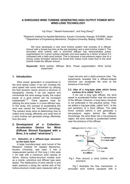
2.2. Idea of a ring-type plate which forms<br />
vortices (It is called “brim”)<br />
If we use a long type diffuser, the wind<br />
speed is accelerated further near the entrance<br />
of the diffuser. However, a long heavy structure<br />
is not preferable in the practical sense. Then<br />
we added a ring-type plate, called “brim”, to the<br />
exit periphery of a short diffuser. The plate<br />
forms vortices behind it and generates a<br />
low-pressure region behind the diffuser.<br />
Accordingly, the wind flows into a low-pressure<br />
region, the wind velocity is accelerated further<br />
near the entrance of the diffuser.<br />
Fig.1 Flow around a wind turbine with<br />
wind-lens<br />
Fig.1 illustrates the flow mechanism. A<br />
shrouded wind turbine equipped with a
immed diffuser came into existence in this<br />
way. We call it the wind-lens turbine.<br />
Next we add an appropriate structure for<br />
entrance, called an inlet shroud, to the entrance<br />
of the diffuser with a brim. The inlet shroud<br />
makes wind easy to flow into the diffuser.<br />
Viewed as a whole, the collection- acceleration<br />
device consists of a venturi-shaped structure<br />
with a brim.<br />
As for other parameters, we have examined<br />
the diffuser opening angle, the hub ratio, and the<br />
center-body length. Then the optimal shape of a<br />
brimmed diffuser was found 3) . In addition, we are<br />
now examining the turbine blade shape in order<br />
to acquire higher output power. As illustrated in<br />
Fig.2, when a brimmed diffuser is applied (see<br />
Fig.3), a remarkable increase in the output power<br />
coefficient (Cw=P/0.5ρAU 3 , P: output power, A:<br />
swept area of a turbine blade) of approximately<br />
4-5 times that of a conventional wind turbine is<br />
achieved in field experiment.<br />
equipped with a brimmed diffuser rotate<br />
following the change in the wind direction,<br />
like a weathercock. As a result, the wind<br />
turbine automatically turns to face the<br />
wind.<br />
) Significant reduction in wind turbine noise:<br />
Basically, an airfoil section of the turbine<br />
blade, which gives the best performance in<br />
a low-tip speed ratio range, is chosen.<br />
Since the vortices generated from the<br />
blade tips are considerably suppressed<br />
through the interference with the boundary<br />
layer within the diffuser shroud, the<br />
aerodynamic noise is reduced substantially<br />
4,5) .<br />
) Improved safety: The wind turbine, rotating<br />
at a high speed, is shrouded by a structure<br />
and is also safe against damage from<br />
broken blades.<br />
Fig.3 500W wind-lens turbine (rotor<br />
diameter 0.7m)<br />
Fig.2 Field experiment of 500W wind turbine with<br />
wind-lens<br />
2.3. Characteristics of a wind turbine with<br />
brimmed diffuser shroud<br />
Fig.3 shows the first prototype of a wind<br />
turbine equipped with a brimmed diffuser<br />
shroud (rated power 500W, rotor diameter of<br />
0.7m). The diffuser length of this model is 1.47<br />
times as long as the diameter of the diffuser<br />
throat D (L t =1.47D). The width of the brim is<br />
h=0.5D. The important features of this wind<br />
turbine equipped with a brimmed diffuser<br />
shroud are as follows.<br />
) Four-fivefold increase in output power<br />
compared to conventional wind turbines<br />
due to concentration of the wind energy<br />
(“wind-lens” technology).<br />
) Brim-based yaw control: The brim at the<br />
exit of the diffuser makes wind turbines<br />
3. Development of a Shrouded Wind<br />
Turbine with Compact Brimmed<br />
Diffuser<br />
For the application to a mid-size wind<br />
turbine, we have been developing a<br />
compact-type brimmed diffuser. For the 500W<br />
wind-lens turbine, the length of brimmed<br />
diffuser L t is 1.47D and still relatively long as a<br />
collection-acceleration structure for wind. If we<br />
apply this brimmed diffuser to a larger wind<br />
turbine in size, the wind load to this structure<br />
and the weight of this structure becomes<br />
severe problems. Therefore, to overcome the<br />
above-mentioned problems, we propose a very<br />
compact collection-acceleration structure<br />
(compact brimmed diffuser), the length L t of<br />
which is quite short compared to D, i.e., L t <<br />
0.4D. We made a couple of compact brimmed<br />
diffusers in a range of a relatively short one to a<br />
very short one of L t = 0.1– 0.4D. We conducted<br />
the output performance test of those wind-lens
turbines with compact brimmed diffuser in a<br />
wind tunnel experiment and also carried out a<br />
field test using a prototype 1kW type model.<br />
3.1. Experimental method in output<br />
performance test of compact wind-lens<br />
turbines<br />
A large wind tunnel with a measurement<br />
section of 15m long, 3.6m wide, 2m high was<br />
used. To avoid a blockage effect, removing the<br />
ceiling and both side walls, we used it with an<br />
open-type test section. For the size of the<br />
brimmed diffuser in the present experiment, the<br />
throat diameter D is 1020mm and the rotor<br />
diameter is 1000mm. Fig.4 shows a schematic<br />
of a compact wind-lens turbine. We made four<br />
types of diffusers called A, B, C and S-type with<br />
different sectional shapes, as shown in Fig.5.<br />
Table 1 shows the length ratios L t /D and the<br />
area ratios of (exit area)/(throat area) for each<br />
diffuser model. All diffuser types of A to S show<br />
the almost same L t /D, but show the different<br />
area ratio µ. For S-type, it has a straight<br />
sectional shape as like the 500W prototype.<br />
Other three types of A to C have the curved<br />
sectional shapes, as shown in Fig.5. For C-type,<br />
we adopted the cycloid curve for the sectional<br />
shape. Here, the hub ratio D h /D is 13% and the<br />
tip clearance s is 10mm.<br />
As for the experimental method, connecting<br />
a torque transducer (the rating 10Nm) to the<br />
wind turbine and in the rear of it, an AC torque<br />
motor brake was set for the loading. We<br />
measured the torque Q (N m) and the<br />
rotational speed n (Hz) of the wind turbine in<br />
the condition that the turbine loading was<br />
gradually applied from zero. The calculated<br />
power output P (W)= Q2πn is shown as a<br />
performance curve. The shrouded wind turbine<br />
model with a compact brimmed diffuser was<br />
supported by a long straight bar from the<br />
measurement bed which was placed in the<br />
downstream and consists of a torque<br />
transducer, a revolution sensor and an AC<br />
torque motor brake, as shown in Fig. 6. The<br />
approaching wind speed U o was 8m/s.<br />
Fig.4 Schematic of wind-lens turbine<br />
500W prototype A B C S<br />
Diffuser Prototype A B C S<br />
Lt/D 1.470 0.225 0.221 0.221 0.225<br />
Table1 Parameters of wind-lens shapes<br />
Fig.6<br />
Fig.5. Wind-lens shapes<br />
µ 2.345 1.173 1.288 1.294 1.119<br />
Output performance test of<br />
wind-lens turbine<br />
3.2. Selection of compact brimmed diffuser<br />
shape as wind-lens<br />
Fig. 7 shows the experimental result of the<br />
shrouded wind turbines with compact brimmed<br />
diffuser of Aii, Bii, Cii and Sii type. The height of<br />
brim is 10%, i.e., h=0.1D. The horizontal axis<br />
shows the blade tip speed ratio λ=ωr/U o , here<br />
ω is the angular frequency, 2πn, and r is the<br />
radius of a wind turbine rotor (r=0.58m). The<br />
vertical axis shows the power coefficient C w<br />
(=P/(0.5ρU ∞ 3 A), A is the rotor swept area, πr 2 ).<br />
The wind turbine blade with MEL wing section<br />
contour was designed using a three-bladed<br />
wind turbine resulting in an optimum tip speed<br />
ratio of 5.0. As shown in Fig. 7, when a compact<br />
brimmed diffuser is applied, we have<br />
successfully achieved a remarkable increase in<br />
the output power coefficient approximately 1.9–<br />
2.4 times as large as a bare wind turbine.<br />
Namely, the C w is 0.37 for a bare wind turbine,<br />
on the other hand, the C w is 0.7 – 0.88 for a<br />
wind turbine with a compact brimmed diffuser.<br />
The experimental results shown in Fig. 7 were
obtained under the same wind speed and the<br />
swept area of a wind turbine.<br />
First, we compare Aii type with Sii type in<br />
Fig.7. Both types have an almost same area<br />
ratio µ. The C w of Aii is higher than Sii. It means<br />
that the curved sectional shape is preferable to<br />
the straight one. Furthermore, it is noted that<br />
the Bii and Cii types show higher C w compared<br />
to Aii type. It means that if the boundary-layer<br />
flow along the inside wall of curved diffuser<br />
dose not show a large separation, Bii and Cii<br />
types, which have a larger area ratio µ<br />
compared to that of Aii, are suitable to a<br />
compact diffuser.<br />
Table2 Parameters of C-type wind-lens<br />
Fig.8 Power coefficients of wind-lens turbine<br />
with C-type wind-lens (h=0.1D)<br />
Fig.7 Power coefficients of various wind-lens<br />
turbines<br />
3.3. Output power of wind-lens turbine with<br />
the compact diffuser length<br />
From the experimetal result shown in Fig.7,<br />
we discuss further C-type diffuser as the<br />
compact collection-accelaration structure. For<br />
the next step, we investigated the length effect<br />
of the C-type diffuser on the output<br />
performance of wind-lens turbines. We<br />
prepared four kinds of C-type diffusers from C0<br />
to Ciii, as described in Table 2. Fig. 8 shows the<br />
result of output performance with the four<br />
C-type diffuser lengths. The brim height is 10%,<br />
i.e., h=0.1D. Fig.9 also shows the variation of<br />
C w,max with the diffuser length L t /D, here C w,max<br />
is the maximun value of C w in the output<br />
perforamance curves as is shown in Fig.8. As it<br />
is expected, the C w,max value becomes smaller,<br />
as the diffuser length L t /D becomes smaller.<br />
However, when the brim height is larger than<br />
10%, i.e., in case of h0.1D, the C w of a<br />
wind-lens turbine with C0-type diffuser shows<br />
almost twofold increase compared to a bare<br />
wind turbine and the one with Ciii-type diffuser<br />
shows 2.6 times increase. Thus, we can expect<br />
2-3 times increase in output perforamnce, even<br />
if we use a very compact brimmed diffuser as<br />
the wind-lens structure.<br />
W.T. only<br />
C0<br />
C<br />
C<br />
C<br />
Fig.9 Maximum power coefficient Cw max vs.<br />
C-type wind-lens length<br />
3.4. Field experiment<br />
As described before, one of the merits of<br />
wind-lens turbine is the brim-based yaw control.<br />
Namely, owing to the brim, the wind-lens<br />
turbine automatically turns to face the wind.<br />
However, for the comapct wind-lens structure, it<br />
is difficult to realize the wind-lens turbine as the<br />
upwind-type wind turbine. Therefore, we made<br />
a prototype compact wind-lens turbine as a<br />
downwind-type one.<br />
3.4.1. 1kW wind-lens turbine<br />
For 1kW downwind-type wind turbine, we<br />
selected the Cii-type diffuser (L t /D=0.22) as the<br />
Diffuser C C C C0<br />
Lt/D 0.371 0.221 0.137 0.100<br />
µ 1.555 1.294 1.193 1.138
wind-lens structure. The brim height is 15%, i.e.,<br />
h=0.15D. Here, D is 1400mm and the rotor<br />
diameter is 1380mm. Fig.10 shows the<br />
prototype 1kW wind-lens turbine. We<br />
conducted a field experiment using this 1kW<br />
wind turbine. Fig.11 shows the result of<br />
performance test on a windy day. The field data<br />
are plotted as 10 minitues average data. The<br />
power curve is plotted along the C w =1.0 curve<br />
and the high output performance of the present<br />
wind-lens turbine is demonstrated. We obtained<br />
threefold increase in output power as compared<br />
to conventional (bare) wind turbines due to<br />
concentration of the wind energy.<br />
are plotted as 1 minitues average data. The<br />
power curve is plotted along the C w =1.0 curve<br />
and the high output performance of the present<br />
wind-lens turbine is demonstrated. We obtained<br />
2.5 times increase in output power as<br />
compared to conventional (bare) wind turbines.<br />
Fig.12 5kW wind-lens turbine (rotor diameter<br />
2.5m), downwind type<br />
Fig.10 1kW wind-lens turbine (rotor diameter<br />
1.38m), downwind type<br />
Fig.11<br />
Field experiment of 1kW wind-lens<br />
turbine<br />
3.4.2. 5kW wind-lens turbine<br />
A 5kW wind-lens turbine was also developed.<br />
We selected the Cii-type diffuser (L t /D=0.22) as<br />
the wind-lens structure. The brim height is 10%,<br />
i.e., h=0.1D. Here, D is 2560mm and the rotor<br />
diameter is 2500mm. Fig.12 shows the<br />
prototype 5kW wind-lens turbine. We<br />
conducted a field experiment using this 5kW<br />
wind turbine. Fig.13 shows the result of<br />
performance test on a windy day. The field data<br />
Fig.13<br />
Field experiment of 5kW wind-lens<br />
turbine<br />
3.5. Application of 5kW wind-lens turbines<br />
for supplying stable electricity to an<br />
irrigation plant in China<br />
To stop desertification in northwest China,<br />
an area facing deepening global environmental<br />
problems, and to turn the land into green land,<br />
irrigation and greenery projects began by<br />
capitalizing on the vast wind energy as a power<br />
source in the northwest, as shown in Fig. 14. A<br />
small wind-lens turbine, which can be moved<br />
and installed easily, is the best means of power<br />
generation in this area without power grid<br />
infrastructure. The highly efficient wind-lens<br />
turbines offering the great small windmill
performance, developed by the authors’ group,<br />
were improved, remodeled and enlarged<br />
through technological development for the<br />
application to a desert area. Six units of 5kW<br />
wind-lens turbines were introduced to build a<br />
wind farm for irrigation, and their effectiveness<br />
for the greenery project has been examined.<br />
Thus, a plant was constructed for pumping<br />
irrigation system by building a network of<br />
distributed power sources, ensuring that<br />
micro-grids will stably supply electric power by<br />
combining the network and power storage<br />
technology using batteries. This plant initiated<br />
to implement tree planting and greening the<br />
desert, and its effectiveness will be examined.<br />
more mass flow to the wind turbine inside the<br />
diffuser.<br />
For the purpose of the application to a<br />
mid-size wind turbine, we developed a very<br />
compact brimmed diffuser (wind-lens structure).<br />
Using this compact brimmed diffuser, we<br />
achieved two-threefold increase in output<br />
power as compared to conventional (bare) wind<br />
turbines due to concentration of the wind<br />
energy.<br />
Incidentally, if we adopt the swept area A*<br />
instead of A (due to the rotor diameter), where<br />
A* is the circular area due to the outer diameter<br />
of brim at diffuser exit, the output coefficient<br />
based on A* becomes 0.48-0.52 for those<br />
compact wind-lens turbines. It is still larger than<br />
the C w (=0.37) of conventional wind turbines. It<br />
means that the compact wind-lens turbine<br />
clearly show higher efficiency compared to<br />
conventional wind turbines, even if the rotor<br />
diameter of a conventional wind turbine is the<br />
same as the brim diameter.<br />
References<br />
Fig. 14 An irrigation-greenery plant using<br />
wind energy (5kW wind-lens turbine<br />
farm) in a desert area in Gansu, China<br />
4. Conclusion<br />
A collection-acceleration devise for wind,<br />
“the brimmed diffuser”, which shrouds a wind<br />
turbine, is developed. Significant increase in<br />
the output power of a micro-scale wind turbine<br />
is obtained. With a relatively long diffuser (L t<br />
=1.47D), a remarkable increase in the output<br />
power of approximately 4-5 times that of a<br />
conventional wind turbine is achieved. This is<br />
because a low-pressure region due to a strong<br />
vortex formation behind the broad brim draws<br />
[1] O. Igra, “Research and development for<br />
shrouded wind turbines”, Energy<br />
Conversion and Management 21, 1981,<br />
pp.13-48.<br />
[2] B. L. Gilbert and K. M. Foreman,<br />
“Experiments with a diffuser-augmented<br />
model wind turbine”, Trans. ASME, J,<br />
Energy Resources Technology 105, 1983,<br />
pp.46-53.<br />
[3] Y. Ohya, T. Karasudani, A. Sakurai, M. Inoue,<br />
“Development of a high- performance wind<br />
turbine equipped with a brimmed diffuser<br />
shroud”, Trans. of the Japan Society for<br />
Aeronautical and Space Sciences, 49-163,<br />
2006, pp.18-24.<br />
[4] K. Abe, M. Nishida, A. Sakurai, Y. Ohya, H.<br />
Kihara, E. Wada, K. Sato, “Experimental and<br />
numerical investigations of flow fields behind<br />
a small-type wind turbine with flanged<br />
diffuser”, J. Wind Eng. Ind. Aerodyn. 93,<br />
2005, pp.951-970.<br />
[5] K. Abe, H. Kihara, A. Sakurai, M. Nishida, Y.<br />
Ohya, E. Wada, K. Sato, “An experimental<br />
study of tip-vortex structures behind a small<br />
wind turbine with a flanged diffuser”, Wind<br />
and Structures 9-5, 2006, pp.413-417.