AE 401-- Procedure -- Lab: Nozzle Performance - Clarkson University
AE 401-- Procedure -- Lab: Nozzle Performance - Clarkson University
AE 401-- Procedure -- Lab: Nozzle Performance - Clarkson University
Create successful ePaper yourself
Turn your PDF publications into a flip-book with our unique Google optimized e-Paper software.
<strong>AE</strong> <strong>401</strong> – Spring 2005<br />
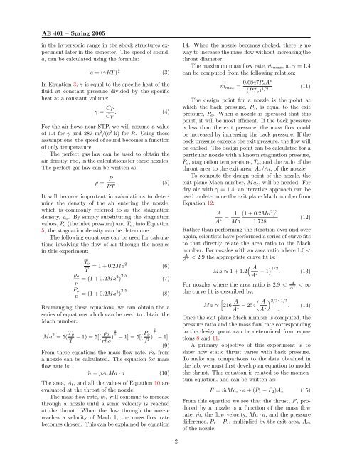
in the hypersonic range in the shock structures experiment<br />
later in the semester. The speed of sound,<br />
a, can be calculated using the formula:<br />
a = (γRT ) 1 2<br />
(3)<br />
In Equation 3, γ is equal to the specific heat of the<br />
fluid at constant pressure divided by the specific<br />
heat at a constant volume:<br />
γ = C P<br />
C V<br />
. (4)<br />
For the air flows near STP, we will assume a value<br />
of 1.4 for γ and 287 m 2 /(s 2 k) for R. Using these<br />
assumptions, the speed of sound becomes a function<br />
of only temperature.<br />
The perfect gas law can be used to obtain the<br />
air density, rho, in the calculations for these nozzles.<br />
The perfect gas law can be written as:<br />
ρ =<br />
P RT<br />
(5)<br />
It will become important in calculations to determine<br />
the density of the air entering the nozzle,<br />
which is commonly referred to as the stagnation<br />
density, ρ o . By simply substituting the stagnation<br />
values, P o (the inlet pressure) and T o , into Equation<br />
5, the stagnation density can be determined.<br />
The following equations can be used for calculations<br />
involving the flow of air through the nozzles<br />
in this experiment:<br />
T o<br />
T = 1 + 0.2Ma2 (6)<br />
ρ o<br />
ρ = (1 + 0.2Ma2 ) 2.5 (7)<br />
P o<br />
P = (1 + 0.2Ma2 ) 3.5 (8)<br />
Rearranging these equations, we can obtain the a<br />
series of equations which can be used to obtain the<br />
Mach number:<br />
Ma 2 = 5( T o<br />
T − 1) = 5[( ρ 2<br />
o<br />
rho ) 5<br />
− 1] = 5[( P 2<br />
o<br />
P ) 7<br />
− 1]<br />
(9)<br />
From these equations the mass flow rate, ṁ, from<br />
a nozzle can be calculated. The equation for mass<br />
flow rate is:<br />
ṁ = ρA t Ma · a (10)<br />
The area, A t , and all the values of Equation 10 are<br />
evaluated at the throat of the nozzle.<br />
The mass flow rate, ṁ, will continue to increase<br />
through a nozzle until a sonic velocity is reached<br />
at the throat. When the flow through the nozzle<br />
reaches a velocity of Mach 1, the mass flow rate<br />
becomes choked. This can be explained by equation<br />
14. When the nozzle becomes choked, there is no<br />
way to increase the mass flow without increasing the<br />
throat diameter.<br />
The maximum mass flow rate, ṁ max , at γ = 1.4<br />
can be computed from the following relation:<br />
ṁ max = 0.6847P oA ∗<br />
(RT o ) 1/2 (11)<br />
The design point for a nozzle is the point at<br />
which the back pressure, P 2 , is equal to the exit<br />
pressure, P e . When a nozzle is operated that this<br />
point, it will be most efficient. If the back pressure<br />
is less than the exit pressure, the mass flow could<br />
be increased by increasing the back pressure. If the<br />
back pressure exceeds the exit pressure, the flow will<br />
be choked. The design point can be calculated for a<br />
particular nozzle with a known stagnation pressure,<br />
P o , stagnation temperature, T o , and the ratio of the<br />
throat area to the exit area, A e /A t , of the nozzle.<br />
To compute the design point of the nozzle, the<br />
exit plane Mach number, Ma e , will be needed. For<br />
dry air with γ = 1.4, an iterative approach can be<br />
used to determine the exit plane Mach number from<br />
Equation 12:<br />
A<br />
A ∗ = 1 (1 + 0.2Ma 2 ) 3<br />
Ma 1.728<br />
(12)<br />
Rather than performing the iteration over and over<br />
again, scientists have performed a series of curve fits<br />
to that directly relate the area ratio to the Mach<br />
number. For nozzles with an area ratio where 1.0 <<br />
A<br />
A ∗<br />
< 2.9 the appropriate curve fit is:<br />
Ma ≈ 1 + 1.2( A<br />
A ∗ − 1) 1/2<br />
. (13)<br />
For nozzles where the area ratio is 2.9 < A A<br />
< ∞<br />
∗<br />
the curve fit is described by:<br />
[<br />
Ma ≈ 216 A ( A<br />
) 2/3 ] 1/5.<br />
A ∗ − 254 (14)<br />
A ∗<br />
Once the exit plane Mach number is computed, the<br />
pressure ratio and the mass flow rate corresponding<br />
to the design point can be determined from equations<br />
8 and 11.<br />
A primary objective of this experiment is to<br />
show how static thrust varies with back pressure.<br />
To make any comparisons to the data obtained in<br />
the lab, we must first develop an equation to model<br />
the thrust. This equation is related to the momentum<br />
equation, and can be written as:<br />
F = ṁMa e · a + (P 1 − P 2 )A e (15)<br />
From this equation we see that the thrust, F , produced<br />
by a nozzle is a function of the mass flow<br />
rate, ṁ, the flow velocity, Ma · a, and the pressure<br />
difference, P 1 − P 2 , multiplied by the exit area, A e ,<br />
of the nozzle.<br />
2


