
You also want an ePaper? Increase the reach of your titles
YUMPU automatically turns print PDFs into web optimized ePapers that Google loves.
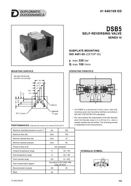
41 640/109 ED<br />
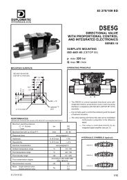
<strong>DSB5</strong><br />
SELF-REVERSING VALVE<br />
SERIES 10<br />
SUBPLATE MOUNTING<br />
ISO 4401-05 (CETOP 05)<br />
p max 320 bar<br />
Q max 100 l/min<br />
MOUNTING SURFACE<br />
OPERATING PRINCIPLE<br />
ISO 4401-05-04-0-94<br />
(CETOP 4.2-4-05-320)<br />
21.4<br />
6.3<br />
16.7<br />
3.2<br />
54<br />
50.8<br />
37.3<br />
27<br />
46<br />
32.5<br />
T<br />
P<br />
A<br />
B<br />
M6x10<br />
Ø11.2 (max)<br />
Attacco optional "T"<br />
facoltativo “T” port<br />
— The <strong>DSB5</strong> is a directional control valve, with selfreversing<br />
spool and mounting interface according to<br />
ISO 4401 (CETOP RP121H) standards.<br />
PERFORMANCES (measured with mineral oil of viscosity 36 cSt at 50°C)<br />
— The valve realizes the reciprocation of the flow direction<br />
when the flowrate stops in A or B line (f.e., when a<br />
cylinder reaches the end stroke). The reversing process<br />
is independent of the load pressure.<br />
Maximum operating pressure on port P bar 320<br />
Maximum flow rate l/min 100<br />
Minimum allowed flow rate l/min 10<br />
Minimum allowed pressure l/min 60<br />
Pressure drop Δp-Q<br />
see paragraph<br />
Ambient temperature range °C -20 / +50<br />
HYDRAULIC SYMBOL<br />
Fluid temperature range °C -20 / +80<br />
Fluid viscosity range cSt 10 ÷ 400<br />
Fluid contamination degree<br />
according to ISO 4406:1999<br />
class 20/18/15<br />
Recommended viscosity cSt 25<br />
Mass<br />
kg<br />
41 640/109 ED<br />
1/4
<strong>DSB5</strong><br />
SERIES 10<br />
1 - IDENTIFICATION CODE<br />
D S B 5 - RTA / 10<br />
Directional control valve<br />
with spool<br />
With self reversing spool<br />
Size:<br />
5 = ISO 4401-05 (CETOP 05)<br />
Seals:<br />
N = NBR seals for mineral oil (standard)<br />
V = FPM seals for special fluids<br />
Series No.:<br />
(the overall and mounting dimensions remain<br />
unchanged from 10 to 19)<br />
Spool type<br />
2 - PRESSURE DROPS Δp-Q (values obtained with viscosity 36 cSt at 50 °C)<br />
3 - HYDRAULIC FLUIDS<br />
Use mineral oil-based hydraulic fluids HL or HM type, according to ISO 6743-4. For these fluids, use NBR seals. For fluids HFDR type<br />
(phosphate esters) use FPM seals (code V). For the use of other kinds of fluid such as HFA, HFB, HFC, please consult our technical<br />
department. Using fluids at temperatures higher than 80 °C causes a faster degradation of the fluid and of the seals characteristics.<br />
The fluid must be preserved in its physical and chemical characteristics.<br />
4 - INSTALLATION<br />
Configurations with centering and return springs can be mounted in any position; type RK valves -<br />
without springs and with mechanical detent - must be mounted with the longitudinal axis horizontal.<br />
Valve fixing is by means of screws or tie rods, with the valve mounted on a lapped surface, with values<br />
of planarity and smoothness that are equal to or better than those indicated in the drawing. If the<br />
minimum values of planarity and/or smoothness are not met, fluid leakage between valve and<br />
mounting surface can easily occur.<br />
Surface finishing<br />
41 640/109 ED<br />
2/4
<strong>DSB5</strong><br />
SERIES 10<br />
5 - OVERALL AND MOUNTING DIMENSIONS<br />
dimensions in mm<br />
1 Mounting surface with sealing rings:<br />
No. 5 OR type 2050 (12.42x1.78)<br />
90 shore<br />
6 - APPLICATION EXAMPLE<br />
We suggest to use the circuit shown in the application example<br />
where, when the pump start to give flow the cylinder is ready to<br />
retract.<br />
When the pressure on the actuator exceeds the value set on the<br />
pressure relief valve, the flow in the <strong>DSB5</strong> valve stops and the spool<br />
inside moves causing the reverse of the flow.<br />
To set the system relief valve, the self-reversing function must be<br />
inactive.<br />
To do so, close the shut-off valve, start the pump, set the pressure<br />
relief valve, stop the pump. Then, open the shut off valve and restart<br />
the pump.<br />
To work properly the valve needs an area ratio of the cylinder<br />
chambers included between 1 ÷ 1,25 and 1 ÷ 2.<br />
41 640/109 ED<br />
3/4
<strong>DSB5</strong><br />
SERIES 10<br />
7 - SUBPLATES (See catalogue 51 000)<br />
<strong>DSB5</strong><br />
Type with rear ports<br />
Type with side ports<br />
PMD4-AI4G<br />
PMD4-AL4G<br />
41 640/109 ED<br />
4/4