Compact Nanosecond Pulse Generator
Compact Nanosecond Pulse Generator
Compact Nanosecond Pulse Generator

You also want an ePaper? Increase the reach of your titles
YUMPU automatically turns print PDFs into web optimized ePapers that Google loves.
<strong>Pulse</strong>d Power Technology<br />
<strong>Compact</strong> <strong>Nanosecond</strong> <strong>Pulse</strong> <strong>Generator</strong><br />
N.V. Zharova, I.V. Lavrinovich, V.F. Feduschak, and A.A. Erfort<br />
Institute of High Current Electronics SB RAS, 2/3, Academichesky ave., Tomsk, 634055, Russia<br />
Abstract – A compact nanosecond pulse generator<br />
was designed and tested. The generator has a specially<br />
designed unit consisting of an HCEIcap 100-<br />
0.2 capacitor and a multigap switch. The total inductance<br />
of the unit is 20 nH. The modifications<br />
made in the design allowed an increase in energy<br />
density up to 370 J/l at an electric field strength of<br />
200 kV/mm. The volume of the capacitor active<br />
part is 2.3 l. In the short-circuit mode, the unit ensures<br />
a current up to 200 kA with a risetime of<br />
100 ns at a charge voltage of 90 kV. The dimensions<br />
of the capacitor active part are<br />
Ø80 × Ø160 × 160 mm. With an X-pinch load (four<br />
W wires of diameter 15 µm), the rate of rise of the<br />
current is 140 kA/70 ns and the X-ray pulsewidth is<br />
2 ns. The peculiarity of the load is that it absorbs a<br />
small amount of energy compared to the energy<br />
stored in the capacitor. Therefore, it is proposed to<br />
use exploded wires in the discharge circuit of the<br />
capacitor to ensure a current cutoff at the instant<br />
the energy stored in the capacitor is close to zero.<br />
Thus, it will be possible to suppress or preclude the<br />
oscillation mode of the capacitor and hence to increase<br />
its lifetime.<br />
of an HCEIcap 100-0.2 capacitor and a multigap<br />
switch made it possible to design a compact nanosecond<br />
pulse generator operating into an X-pinch load.<br />
Below we consider the generator at greater length.<br />
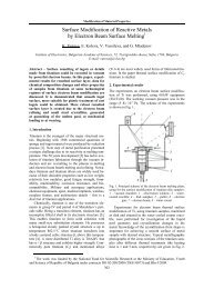
2. Design of the generator<br />
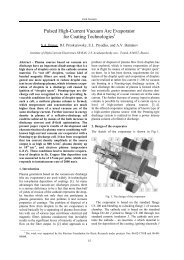
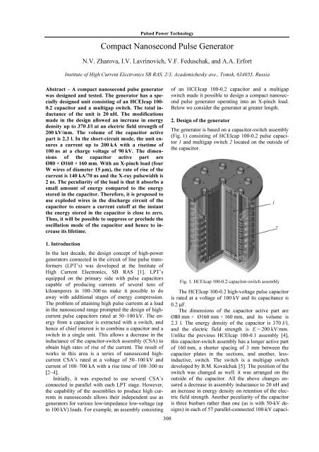
The generator is based on a capacitor-switch assembly<br />
(Fig. 1) consisting of HCEIcap 100-0.2 pulse capacitor<br />
1 and multigap switch 2 located on the outside of<br />
the capacitor.<br />
1<br />
2<br />
1. Introduction<br />
In the last decade, the design concept of high-power<br />
generators connected in the circuit of line pulse transformers<br />
(LPT’s) was developed at the Institute of<br />
High Current Electronics, SB RAS [1]. LPT’s<br />
equipped on the primary side with pulse capacitors<br />
capable of producing currents of several tens of<br />
kiloamperes in 100–300 ns make it possible to do<br />
away with additional stages of energy compression.<br />
The problem of attaining high pulse currents at a load<br />
in the nanosecond range prompted the design of highcurrent<br />
pulse capacitors rated at 50–100 kV. The energy<br />
from a capacitor is extracted with a switch, and<br />
hence of chief interest is to combine a capacitor and a<br />
switch in a single unit. This allows a decrease in the<br />
inductance of the capacitor-switch assembly (CSA) to<br />
obtain high rates of rise of the current. The result of<br />
works in this area is a series of nanosecond highcurrent<br />
CSA’s rated at a voltage of 50–100 kV and<br />
current of 100–700 kA with a rise time of 100–300 ns<br />
[2–4].<br />
Initially, it was expected to use several CSA’s<br />
connected in parallel with each LPT stage. However,<br />
the capability of the assemblies to produce high currents<br />
in nanoseconds allows their independent use as<br />
generators for various low-impedance low-voltage (up<br />
to 100 kV) loads. For example, an assembly consisting<br />
300<br />
Fig. 1. HCEIcap 100-0.2 capacitor-switch assembly<br />
The HCEIcap 100-0.2 high-voltage pulse capacitor<br />
is rated at a voltage of 100 kV and its capacitance is<br />
0.2 F.<br />
The dimensions of the capacitor active part are<br />
Ø80 mm × Ø160 mm × 160 mm, and its volume is<br />
2.3 l. The energy density of the capacitor is 370 J/l,<br />
and the electric field strength is E = 200 kV/mm.<br />
Unlike the previous HCEIcap 100-0.1 assembly [4],<br />
this capacitor-switch assembly has a longer active part<br />
of 160 mm, a shorter spacing of 3 mm between the<br />
capacitor plates in the sections, and another, lessinductive,<br />
switch. The switch is a multigap switch<br />
developed by B.M. Kovalchuk [5]. The position of the<br />
switch was changed as well: it was arranged on the<br />
outside of the capacitor. All the above changes ensured<br />
a decrease in assembly inductance to 20 nH and<br />
an increase in energy density on retention of the electric<br />
field strength. Another peculiarity of the capacitor<br />
is three busbars rather than one (as is with 50-kV designs)<br />
in each of 57 parallel-connected 100-kV capaci-
Oral Session<br />
tors. This was done to compensate for the stray inductance<br />
arising in non-multichannel switching. Finally,<br />
one more peculiarity of the HCEIcap 100-0.2 capacitor<br />
with external switching [6] is the dynamics of the<br />
action of currents on the plates that is responsible for<br />
their denser packing. The effect shows up with time as<br />
a slight increase in capacitance (within the space factor)<br />
and a decrease in gas release due to better contacts<br />
between the Al plates and the busbars.<br />
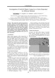
The HCEIcap 100-0.2 assembly was tested in the<br />
short-circuit mode at a charge voltage of 90 kV. Figure<br />
2 shows a waveform of the current obtained in this<br />
mode. It is seen from the waveform that the assembly<br />
ensures a current of 200 kA in 100 ns at a charge voltage<br />
of 90 kV.<br />
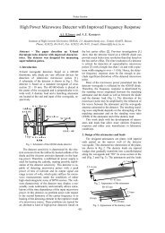
diameter 13 m. The amplitude of the load current<br />
was 160 kA with a rise time of 120 ns. A typical<br />
waveform of the load current is shown in Fig. 4. The<br />
voltage across the capacitor was found by the formula:<br />
1<br />
Ut () U0<br />
IC<br />
() tdt.<br />
C ∫<br />
I, kA U, kV<br />
T, ns<br />
Fig. 4. Waveforms of the load current and capacitor voltage<br />
at a charge voltage U 0 = 87 kV<br />
80 ms/d<br />
200 kA<br />
Fig. 2. Waveform of the current in the short-circuit mode at<br />
a charge voltage of 90 kV<br />
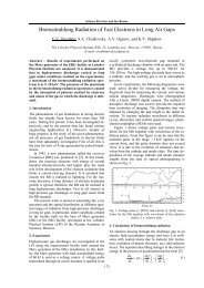
The generator based on the HCEIcap 100-0.2 assembly<br />
also contains a load unit (Fig. 3) located<br />
through the center of the assembly. The arrangement<br />
of the load in the immediate vicinity of the assembly<br />
provides low inductance of the busbars and hence a<br />
slight decrease in the amplitude of the load current.<br />
The peculiarity of the load is that it absorbs a small<br />
amount of energy compared to the energy stored in the<br />
capacitor. Thus, a voltage reversal greater than 50%<br />
arises across the capacitor. This greatly decreases the<br />
lifetime of the pulse capacitor that may cause its failure<br />
with time.<br />
One of the possible ways to suppress this undesirable<br />
effect is to use electrically exploded conductors<br />
(EEC’s) in the discharge circuit of the capacitor<br />
(Fig. 5).<br />
EEC<br />
Load<br />
Fig. 3. X-pinch generator<br />
3. Results<br />
The generator was tested for the operation into an<br />
X-pinch load. The load was four tungsten wires of<br />
301<br />
Fig. 5. Expected design of the capacitor-switch assembly<br />
with EEC’s
<strong>Pulse</strong>d Power Technology<br />
Required parameters were chosen by the EEC algorithm<br />
[7]. With these parameters, the EEC’s slightly<br />
limit the current during its rise time (Fig. 6, а), but<br />
ensure a current cutoff at the instant the energy in the<br />
capacitor is close to zero (Fig. 6, b). An example of<br />
calculated waveforms of the current and voltage is<br />
shown in Fig. 6. The calculation was performed for<br />
30 Cu wires of length 10 cm and diameter 70 µm.<br />
I C , kA<br />
370 J/l at an electric field strength of 200 kV/mm. The<br />
volume of the active part was 2.3 l. The capacitorswitch<br />
assembly in the short-circuit mode produced a<br />
current up to 200 kA in 100 ns at a charge voltage of<br />
90 kV. The dimensions of the capacitor active part are<br />
Ø80 × Ø160 × 160 mm. The rate of rise of the current<br />
at an X-pinch load (four Ø15-m tungsten wires) is<br />
140 kA/70 ns and the X-ray pulsewidth is 2 ns. The<br />
peculiarity of this load is that it absorbs a small<br />
amount of energy compared to the energy stored in the<br />
capacitor. Therefore it was proposed to use exploded<br />
wires in the discharge circuit of the capacitor to ensure<br />
a current cutoff at the instant the energy in the capacitor<br />
is close to zero. Thus, it will be possible to suppress<br />
or preclude the oscillation mode of the capacitor<br />
and hence to increase its lifetime.<br />
References<br />
U, kV<br />
T, ns<br />
а<br />
T, ns<br />
b<br />
Fig. 6. Calculated waveforms of the load current (а) and<br />
voltage across different circuit elements (b)<br />
Conclusion<br />
The compact nanosecond pulse generator was designed<br />
and tested. The generator has a specially designed<br />
assembly consisting of an HCEIcap 100-0.2<br />
capacitor and a multigap switch. The total inductance<br />
of the assembly is 20 nH. The modifications made in<br />
the design allowed an increase in energy density up to<br />
[1] A.A. Kim, B.M. Kovalchuk, A.N. Bastrikov et al.,<br />
in Proc. of the 13th IEEE Int. <strong>Pulse</strong>d Power Conf.,<br />
2001, V. 2, pp. 1491–1494.<br />
[2] N.A. Ratakhin, V.F. Feduschak, A.A. Erfort,<br />
A.V. Saushkin, N.V. Zharova, S.A. Chaikovsky,<br />
and V.I. Oreshkin, “Table-top <strong>Pulse</strong> Power <strong>Generator</strong><br />
for Soft X-Ray Radiography”, in Proc. of<br />
the 14th Int. Symp. on High Current Electronics,<br />
Tomsk, 2006, pp. 511–513.<br />
[3] V.F. Feduschak, N.V. Zharova, I.V. Lavrinovich et<br />
al., “<strong>Compact</strong> <strong>Pulse</strong>d Power <strong>Generator</strong>”, in Proc.<br />
of the 15th Int. Symp. on High Current Electronics,<br />
Tomsk, 2008, pp. 303–304.<br />
[4] N.A. Ratakhin, V.F. Fedushchak, A.A. Erfort et<br />
al., “Development of high-current pulse capacitors<br />
rated at 100 kV”, in Proc. of Int. Conf. on Physics<br />
of <strong>Pulse</strong>d Discharges in Condensed Media, Nikolaev,<br />
2009, pp. 140–142.<br />
[5] A.A. Zherlitsyn, B.M. Kovalchuk, A.V. Kharlov,<br />
and E.V. Kumpyak, “<strong>Pulse</strong>d Current <strong>Generator</strong><br />
with Variable <strong>Pulse</strong> Shape”, in Proc. of the 14th<br />
Int. Symp. on High Current Electronics, Tomsk,<br />
2006, pp. 287–289.<br />
[6] High-voltage capacitor with a built-in controllable<br />
switch by V.S. Verkhovsky, N.V. Zharova,<br />
I.V. Lavrinovich, and V.F. Feduschak, RF Patent<br />
75783: IPC H 01 G 4/00, H 01 T 2/02, applied<br />
08.04.08, published 20.08.08, Bulletin No. 23<br />
[7] E.I. Azarkevich, A.V. Kobluchko, Yu.A. Kotov,<br />
and T.A. Lisetskaya, “Computational model of an<br />
electrical-explosion opening switch, High-voltage<br />
spark gap and electrical-explosion opening<br />
switches”, in Proc. of a Joint Meeting of Scientific<br />
Councils of the USSR AS on Scientific Foundations<br />
of Electrophysics and Electrical Power Engineering<br />
and Problems of <strong>Pulse</strong>d Power Technology,<br />
Tomsk, Nov 27–28, 1986, pp. 109–111.<br />
302