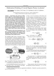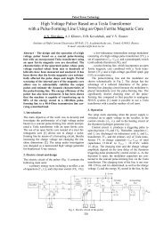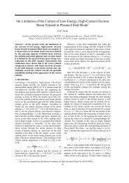
Compact Nanosecond Pulse Generator
Compact Nanosecond Pulse Generator
Compact Nanosecond Pulse Generator

Create successful ePaper yourself
Turn your PDF publications into a flip-book with our unique Google optimized e-Paper software.
Oral Session<br />
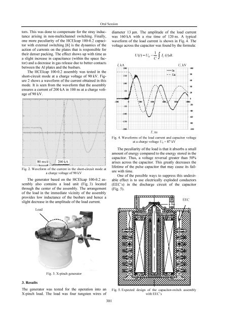
tors. This was done to compensate for the stray inductance<br />
arising in non-multichannel switching. Finally,<br />
one more peculiarity of the HCEIcap 100-0.2 capacitor<br />
with external switching [6] is the dynamics of the<br />
action of currents on the plates that is responsible for<br />
their denser packing. The effect shows up with time as<br />
a slight increase in capacitance (within the space factor)<br />
and a decrease in gas release due to better contacts<br />
between the Al plates and the busbars.<br />
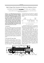
The HCEIcap 100-0.2 assembly was tested in the<br />
short-circuit mode at a charge voltage of 90 kV. Figure<br />
2 shows a waveform of the current obtained in this<br />
mode. It is seen from the waveform that the assembly<br />
ensures a current of 200 kA in 100 ns at a charge voltage<br />
of 90 kV.<br />
diameter 13 m. The amplitude of the load current<br />
was 160 kA with a rise time of 120 ns. A typical<br />
waveform of the load current is shown in Fig. 4. The<br />
voltage across the capacitor was found by the formula:<br />
1<br />
Ut () U0<br />
IC<br />
() tdt.<br />
C ∫<br />
I, kA U, kV<br />
T, ns<br />
Fig. 4. Waveforms of the load current and capacitor voltage<br />
at a charge voltage U 0 = 87 kV<br />
80 ms/d<br />
200 kA<br />
Fig. 2. Waveform of the current in the short-circuit mode at<br />
a charge voltage of 90 kV<br />
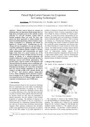
The generator based on the HCEIcap 100-0.2 assembly<br />
also contains a load unit (Fig. 3) located<br />
through the center of the assembly. The arrangement<br />
of the load in the immediate vicinity of the assembly<br />
provides low inductance of the busbars and hence a<br />
slight decrease in the amplitude of the load current.<br />
The peculiarity of the load is that it absorbs a small<br />
amount of energy compared to the energy stored in the<br />
capacitor. Thus, a voltage reversal greater than 50%<br />
arises across the capacitor. This greatly decreases the<br />
lifetime of the pulse capacitor that may cause its failure<br />
with time.<br />
One of the possible ways to suppress this undesirable<br />
effect is to use electrically exploded conductors<br />
(EEC’s) in the discharge circuit of the capacitor<br />
(Fig. 5).<br />
EEC<br />
Load<br />
Fig. 3. X-pinch generator<br />
3. Results<br />
The generator was tested for the operation into an<br />
X-pinch load. The load was four tungsten wires of<br />
301<br />
Fig. 5. Expected design of the capacitor-switch assembly<br />
with EEC’s