Compact Nanosecond Pulse Generator
Compact Nanosecond Pulse Generator
Compact Nanosecond Pulse Generator

Create successful ePaper yourself
Turn your PDF publications into a flip-book with our unique Google optimized e-Paper software.
<strong>Pulse</strong>d Power Technology<br />
<strong>Compact</strong> <strong>Nanosecond</strong> <strong>Pulse</strong> <strong>Generator</strong><br />
N.V. Zharova, I.V. Lavrinovich, V.F. Feduschak, and A.A. Erfort<br />
Institute of High Current Electronics SB RAS, 2/3, Academichesky ave., Tomsk, 634055, Russia<br />
Abstract – A compact nanosecond pulse generator<br />
was designed and tested. The generator has a specially<br />
designed unit consisting of an HCEIcap 100-<br />
0.2 capacitor and a multigap switch. The total inductance<br />
of the unit is 20 nH. The modifications<br />
made in the design allowed an increase in energy<br />
density up to 370 J/l at an electric field strength of<br />
200 kV/mm. The volume of the capacitor active<br />
part is 2.3 l. In the short-circuit mode, the unit ensures<br />
a current up to 200 kA with a risetime of<br />
100 ns at a charge voltage of 90 kV. The dimensions<br />
of the capacitor active part are<br />
Ø80 × Ø160 × 160 mm. With an X-pinch load (four<br />
W wires of diameter 15 µm), the rate of rise of the<br />
current is 140 kA/70 ns and the X-ray pulsewidth is<br />
2 ns. The peculiarity of the load is that it absorbs a<br />
small amount of energy compared to the energy<br />
stored in the capacitor. Therefore, it is proposed to<br />
use exploded wires in the discharge circuit of the<br />
capacitor to ensure a current cutoff at the instant<br />
the energy stored in the capacitor is close to zero.<br />
Thus, it will be possible to suppress or preclude the<br />
oscillation mode of the capacitor and hence to increase<br />
its lifetime.<br />
of an HCEIcap 100-0.2 capacitor and a multigap<br />
switch made it possible to design a compact nanosecond<br />
pulse generator operating into an X-pinch load.<br />
Below we consider the generator at greater length.<br />
2. Design of the generator<br />
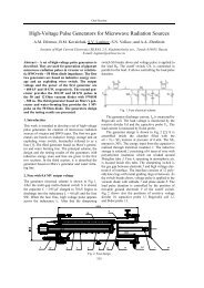
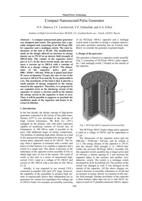
The generator is based on a capacitor-switch assembly<br />
(Fig. 1) consisting of HCEIcap 100-0.2 pulse capacitor<br />
1 and multigap switch 2 located on the outside of<br />
the capacitor.<br />
1<br />
2<br />
1. Introduction<br />
In the last decade, the design concept of high-power<br />
generators connected in the circuit of line pulse transformers<br />
(LPT’s) was developed at the Institute of<br />
High Current Electronics, SB RAS [1]. LPT’s<br />
equipped on the primary side with pulse capacitors<br />
capable of producing currents of several tens of<br />
kiloamperes in 100–300 ns make it possible to do<br />
away with additional stages of energy compression.<br />
The problem of attaining high pulse currents at a load<br />
in the nanosecond range prompted the design of highcurrent<br />
pulse capacitors rated at 50–100 kV. The energy<br />
from a capacitor is extracted with a switch, and<br />
hence of chief interest is to combine a capacitor and a<br />
switch in a single unit. This allows a decrease in the<br />
inductance of the capacitor-switch assembly (CSA) to<br />
obtain high rates of rise of the current. The result of<br />
works in this area is a series of nanosecond highcurrent<br />
CSA’s rated at a voltage of 50–100 kV and<br />
current of 100–700 kA with a rise time of 100–300 ns<br />
[2–4].<br />
Initially, it was expected to use several CSA’s<br />
connected in parallel with each LPT stage. However,<br />
the capability of the assemblies to produce high currents<br />
in nanoseconds allows their independent use as<br />
generators for various low-impedance low-voltage (up<br />
to 100 kV) loads. For example, an assembly consisting<br />
300<br />
Fig. 1. HCEIcap 100-0.2 capacitor-switch assembly<br />
The HCEIcap 100-0.2 high-voltage pulse capacitor<br />
is rated at a voltage of 100 kV and its capacitance is<br />
0.2 F.<br />
The dimensions of the capacitor active part are<br />
Ø80 mm × Ø160 mm × 160 mm, and its volume is<br />
2.3 l. The energy density of the capacitor is 370 J/l,<br />
and the electric field strength is E = 200 kV/mm.<br />
Unlike the previous HCEIcap 100-0.1 assembly [4],<br />
this capacitor-switch assembly has a longer active part<br />
of 160 mm, a shorter spacing of 3 mm between the<br />
capacitor plates in the sections, and another, lessinductive,<br />
switch. The switch is a multigap switch<br />
developed by B.M. Kovalchuk [5]. The position of the<br />
switch was changed as well: it was arranged on the<br />
outside of the capacitor. All the above changes ensured<br />
a decrease in assembly inductance to 20 nH and<br />
an increase in energy density on retention of the electric<br />
field strength. Another peculiarity of the capacitor<br />
is three busbars rather than one (as is with 50-kV designs)<br />
in each of 57 parallel-connected 100-kV capaci-
Oral Session<br />
tors. This was done to compensate for the stray inductance<br />
arising in non-multichannel switching. Finally,<br />
one more peculiarity of the HCEIcap 100-0.2 capacitor<br />
with external switching [6] is the dynamics of the<br />
action of currents on the plates that is responsible for<br />
their denser packing. The effect shows up with time as<br />
a slight increase in capacitance (within the space factor)<br />
and a decrease in gas release due to better contacts<br />
between the Al plates and the busbars.<br />
The HCEIcap 100-0.2 assembly was tested in the<br />
short-circuit mode at a charge voltage of 90 kV. Figure<br />
2 shows a waveform of the current obtained in this<br />
mode. It is seen from the waveform that the assembly<br />
ensures a current of 200 kA in 100 ns at a charge voltage<br />
of 90 kV.<br />
diameter 13 m. The amplitude of the load current<br />
was 160 kA with a rise time of 120 ns. A typical<br />
waveform of the load current is shown in Fig. 4. The<br />
voltage across the capacitor was found by the formula:<br />
1<br />
Ut () U0<br />
IC<br />
() tdt.<br />
C ∫<br />
I, kA U, kV<br />
T, ns<br />
Fig. 4. Waveforms of the load current and capacitor voltage<br />
at a charge voltage U 0 = 87 kV<br />
80 ms/d<br />
200 kA<br />
Fig. 2. Waveform of the current in the short-circuit mode at<br />
a charge voltage of 90 kV<br />
The generator based on the HCEIcap 100-0.2 assembly<br />
also contains a load unit (Fig. 3) located<br />
through the center of the assembly. The arrangement<br />
of the load in the immediate vicinity of the assembly<br />
provides low inductance of the busbars and hence a<br />
slight decrease in the amplitude of the load current.<br />
The peculiarity of the load is that it absorbs a small<br />
amount of energy compared to the energy stored in the<br />
capacitor. Thus, a voltage reversal greater than 50%<br />
arises across the capacitor. This greatly decreases the<br />
lifetime of the pulse capacitor that may cause its failure<br />
with time.<br />
One of the possible ways to suppress this undesirable<br />
effect is to use electrically exploded conductors<br />
(EEC’s) in the discharge circuit of the capacitor<br />
(Fig. 5).<br />
EEC<br />
Load<br />
Fig. 3. X-pinch generator<br />
3. Results<br />
The generator was tested for the operation into an<br />
X-pinch load. The load was four tungsten wires of<br />
301<br />
Fig. 5. Expected design of the capacitor-switch assembly<br />
with EEC’s
<strong>Pulse</strong>d Power Technology<br />
Required parameters were chosen by the EEC algorithm<br />
[7]. With these parameters, the EEC’s slightly<br />
limit the current during its rise time (Fig. 6, а), but<br />
ensure a current cutoff at the instant the energy in the<br />
capacitor is close to zero (Fig. 6, b). An example of<br />
calculated waveforms of the current and voltage is<br />
shown in Fig. 6. The calculation was performed for<br />
30 Cu wires of length 10 cm and diameter 70 µm.<br />
I C , kA<br />
370 J/l at an electric field strength of 200 kV/mm. The<br />
volume of the active part was 2.3 l. The capacitorswitch<br />
assembly in the short-circuit mode produced a<br />
current up to 200 kA in 100 ns at a charge voltage of<br />
90 kV. The dimensions of the capacitor active part are<br />
Ø80 × Ø160 × 160 mm. The rate of rise of the current<br />
at an X-pinch load (four Ø15-m tungsten wires) is<br />
140 kA/70 ns and the X-ray pulsewidth is 2 ns. The<br />
peculiarity of this load is that it absorbs a small<br />
amount of energy compared to the energy stored in the<br />
capacitor. Therefore it was proposed to use exploded<br />
wires in the discharge circuit of the capacitor to ensure<br />
a current cutoff at the instant the energy in the capacitor<br />
is close to zero. Thus, it will be possible to suppress<br />
or preclude the oscillation mode of the capacitor<br />
and hence to increase its lifetime.<br />
References<br />
U, kV<br />
T, ns<br />
а<br />
T, ns<br />
b<br />
Fig. 6. Calculated waveforms of the load current (а) and<br />
voltage across different circuit elements (b)<br />
Conclusion<br />
The compact nanosecond pulse generator was designed<br />
and tested. The generator has a specially designed<br />
assembly consisting of an HCEIcap 100-0.2<br />
capacitor and a multigap switch. The total inductance<br />
of the assembly is 20 nH. The modifications made in<br />
the design allowed an increase in energy density up to<br />
[1] A.A. Kim, B.M. Kovalchuk, A.N. Bastrikov et al.,<br />
in Proc. of the 13th IEEE Int. <strong>Pulse</strong>d Power Conf.,<br />
2001, V. 2, pp. 1491–1494.<br />
[2] N.A. Ratakhin, V.F. Feduschak, A.A. Erfort,<br />
A.V. Saushkin, N.V. Zharova, S.A. Chaikovsky,<br />
and V.I. Oreshkin, “Table-top <strong>Pulse</strong> Power <strong>Generator</strong><br />
for Soft X-Ray Radiography”, in Proc. of<br />
the 14th Int. Symp. on High Current Electronics,<br />
Tomsk, 2006, pp. 511–513.<br />
[3] V.F. Feduschak, N.V. Zharova, I.V. Lavrinovich et<br />
al., “<strong>Compact</strong> <strong>Pulse</strong>d Power <strong>Generator</strong>”, in Proc.<br />
of the 15th Int. Symp. on High Current Electronics,<br />
Tomsk, 2008, pp. 303–304.<br />
[4] N.A. Ratakhin, V.F. Fedushchak, A.A. Erfort et<br />
al., “Development of high-current pulse capacitors<br />
rated at 100 kV”, in Proc. of Int. Conf. on Physics<br />
of <strong>Pulse</strong>d Discharges in Condensed Media, Nikolaev,<br />
2009, pp. 140–142.<br />
[5] A.A. Zherlitsyn, B.M. Kovalchuk, A.V. Kharlov,<br />
and E.V. Kumpyak, “<strong>Pulse</strong>d Current <strong>Generator</strong><br />
with Variable <strong>Pulse</strong> Shape”, in Proc. of the 14th<br />
Int. Symp. on High Current Electronics, Tomsk,<br />
2006, pp. 287–289.<br />
[6] High-voltage capacitor with a built-in controllable<br />
switch by V.S. Verkhovsky, N.V. Zharova,<br />
I.V. Lavrinovich, and V.F. Feduschak, RF Patent<br />
75783: IPC H 01 G 4/00, H 01 T 2/02, applied<br />
08.04.08, published 20.08.08, Bulletin No. 23<br />
[7] E.I. Azarkevich, A.V. Kobluchko, Yu.A. Kotov,<br />
and T.A. Lisetskaya, “Computational model of an<br />
electrical-explosion opening switch, High-voltage<br />
spark gap and electrical-explosion opening<br />
switches”, in Proc. of a Joint Meeting of Scientific<br />
Councils of the USSR AS on Scientific Foundations<br />
of Electrophysics and Electrical Power Engineering<br />
and Problems of <strong>Pulse</strong>d Power Technology,<br />
Tomsk, Nov 27–28, 1986, pp. 109–111.<br />
302