User Manual - OPTI-Solar
User Manual - OPTI-Solar
User Manual - OPTI-Solar

Create successful ePaper yourself
Turn your PDF publications into a flip-book with our unique Google optimized e-Paper software.
<strong>Solar</strong> off-grid Inverter<br />
SP Junior Series<br />
<strong>User</strong> <strong>Manual</strong>
Contents<br />
1 PREFACE .................................................................................... 3<br />
1.1 Glossary ....................................................................................... 3<br />
2 INTRODUCTION ....................................................................... 3<br />
2.1 Description .................................................................................. 3<br />
2.2 Features ....................................................................................... 3<br />
2.3 Appearance .................................................................................. 3<br />
3 INSTALLATION ......................................................................... 4<br />
3.1 Safety ........................................................................................... 4<br />
3.1.1 Positioning ......................................................................... 4<br />
3.1.2 Appliances connected ........................................................ 4<br />
3.2 Connections ................................................................................. 5<br />
4 OPERATION ............................................................................... 5<br />
4.1 Turning ON power ...................................................................... 5<br />
4.2 Charging the battery .................................................................... 6<br />
5 STATUS MONITORING ........................................................... 7<br />
5.1 Alarms ......................................................................................... 7<br />
6 APPENDIX .................................................................................. 8<br />
6.1 Inverter Specifications ................................................................ 8<br />
6.2 <strong>Solar</strong> Charger Controller Specifications ..................................... 9<br />
6.3 Mechanical Specifications .......................................................... 9
1 PREFACE<br />
1.1 Glossary<br />
AC: Alternating Current<br />
LCD: Liquid Crystal Display<br />
PC: Personal Computer<br />
DC: Direct Current<br />
LED: Light Emitting Diode<br />
PV: Photovoltaic<br />
2 INTRODUCTION<br />
2.1 Description<br />
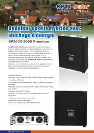
The <strong>Solar</strong> SP Junior series inverters are designed to have access to PV panel DC power<br />
source and provide dual output – DC and AC.<br />
These mini-inverters combined with PV solar modules convert sun light into modified sine<br />
wave AC output power as well as DC output power for various types of electric loads, as well<br />
as offer selectable multistage battery charging current for selectable various battery types.<br />
The built-in 3-stage intelligent charger automatically charges Ni-Cad, GLE/AGM, flooded,<br />
sealed/wet batteries without the risk of overcharge. The compact and modular design makes<br />
utility interactive installations easier and more cost effective. It is a high quality product that<br />
offers the best price-performance ratio in the industry.<br />
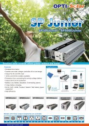
2.2 Features<br />
1. Smallest form-factor<br />
2. Inverter and solar charger controller all-in-one design<br />
3. Output for AC and DC load<br />
4. 12Vdc and 24Vdc modes available with correct/wrong battery capacity auto-detection<br />
5. Output short circuit protection<br />
6. Battery Low, Battery Depleted, Overheating alarms<br />
7. 3-step battery charging<br />
8. Ni-Cad, GLE/AGM, flooded, sealed/wet battery types supported<br />
9. High efficiency<br />
2.3 Appearance<br />
DIP<br />
SWITCH<br />
INDICATOR<br />
USB PORT<br />
( ) TERMINAL<br />
SOLAR<br />
TERMINAL<br />
2 1<br />
CHARGER<br />
ON<br />
DC LOAD<br />
AC<br />
POWER<br />
FAULT<br />
OUTLET<br />
OFF<br />
ON<br />
WA RN ING<br />
DC LOAD<br />
TERMINAL<br />
POWER<br />
SWITCH<br />
AC OUTPUT<br />
SOCKET<br />
( ) TERMINAL<br />
FAN<br />
3
3 INSTALLATION<br />
3.1 Safety<br />
3.1.1 Positioning<br />
Always place the inverter in an environment which is:<br />
1. Well ventilated;<br />
2. Not exposed to direct sunlight or heat;<br />
3. Out of reach of children;<br />
4. Away from water/moisture, oil or grease;<br />
5. Away from any flammable substances.<br />
3.1.2 Appliances connected<br />
If the total power (in watts) of electrical appliances connected, exceeds the output capacity<br />
of the inverter, or after operating for a period of time the temperature of the inverter reaches<br />
60˚C, the inverter shall cut off AC output following the command from the protection circuit.<br />
0<br />
60 C<br />
.<br />
※WARNING※ FLUORESCENT LAMP<br />
Do not use this device with fluorescent lamps.<br />
Glow switch<br />
AC IN<br />
Power Factor<br />
Capacitor<br />
a b<br />
Lamp<br />
BALLASTS<br />
4
3.2 Connections<br />
CAUTION: Do not reverse the polarity of DC side. (+) of SOLAR PANEL and BATTERY<br />
and DC LOAD should be connected to (+) of terminal as per the printing on the inverter. The<br />
(-) should be connected to the (-) terminal.<br />
NOTE: Do not run DC load and AC load at same time, as it is easy to miscalculate the total<br />
load value and overload the inverter.<br />
4 OPERATION<br />
4.1 Turning ON power<br />
Step 1:<br />
Set the power switch at OFF position.<br />
2 1<br />
CHARGER<br />
ON<br />
DC LOAD<br />
FAULT<br />
OFF<br />
ON<br />
AC<br />
OUTLET<br />
POWER<br />
WARNING<br />
OFF<br />
ON<br />
5
Step 2:<br />
When connecting appliances, be sure to turn ON the inverter first. Then, turn ON<br />
the power switch of the appliance.<br />
TURN ON<br />
SECONDLY<br />
2 1<br />
AC OUTPUT<br />
TURN ON<br />
FIRSTLY<br />
OFF<br />
ON<br />
ON<br />
Do not overload the inverter. When connecting appliances, make sure the total<br />
starting power capacity does not exceed the maximum output staring power of the<br />
inverter.<br />
4.2 Charging the battery<br />
Do not reverse the polarity of DC side. Please set the DIP switch correctly according to<br />
the battery type. The DC load connected must not exceed the power rating of the inverter.<br />
DIP SWITCH<br />
2 1<br />
ON<br />
2 1<br />
ON<br />
AC<br />
OUTLET<br />
BATTERY<br />
OFF<br />
ON<br />
SOLAR PANEL<br />
SOLAR INVERTER<br />
DC LOAD<br />
6
NOTE: Do not run DC load and AC load at same time, as it is easy to miscalculate the total<br />
load value and overload the inverter.<br />
DIP switch settings for different battery types:<br />
DIP switch 2 1 Bulk Float Battery Type<br />
OFF OFF 15V 14.5V NI-CAD<br />
ON OFF 14V 13.8V GLE / AGM<br />
OFF ON 14V 13.5V Flooded<br />
ON ON 14V 13.2V Sealed / Wet<br />
<strong>Solar</strong> charging stages:<br />
VOLTAGE<br />
NIGHT<br />
1 2 3<br />
BULK PWM FLOAT<br />
NIGHT<br />
TIME<br />
5 STATUS MONITORING<br />
5.1 Alarms<br />
Inverter warning signal:<br />
Battery Low pre-alarm: bi---------bi---------bi<br />
Overheat pre-alarm: bi---bi---bi---bi---bi<br />
Overload pre-alarm: bi-bi-bi-bi-bi-bi-bi<br />
7
6 APPENDIX<br />
6.1 Inverter Specifications<br />
Model SP300-Junior SP600-Junior<br />
CAPACITY Watt 300W 600W<br />
Voltage range (DC)<br />
12Vdc mode<br />
10 ~ 15Vdc<br />
24Vdc mode<br />
20 ~ 30Vdc<br />
INPUT Current at full load<br />
12Vdc mode 30A 60A<br />
24Vdc mode 15A 30A<br />
Current in standby mode<br />
12Vdc mode < 0.5A < 0.6A<br />
24Vdc mode < 0.4A < 0.4A<br />
Voltage range (AC)<br />
220 ~ 240Vac<br />
OUTPUT<br />
Output wave form<br />
Frequency<br />
Modified sine wave<br />
50 / 60Hz<br />
Continuous output power 300W 600W<br />
Peak output power 900W 1500W<br />
EFFICIENCY Inverter efficiency 85 ~ 90%<br />
12Vdc mode<br />
10.5Vdc ±0.5V<br />
Battery Low pre-alarm<br />
24Vdc mode<br />
21.0Vdc ±0.5V<br />
BATTERY<br />
12Vdc mode<br />
10.0Vdc ±0.5V<br />
Battery Low shutdown<br />
24Vdc mode<br />
20.0Vdc ±0.5V<br />
Thermal protection<br />
60˚C ±5˚C<br />
PROTECTION<br />
Auto-operating fan<br />
Overload protection<br />
Output short circuit protection<br />
Battery 12/24V mismatch protection<br />
Temperature or load dependent<br />
CPU controlled<br />
CPU controlled<br />
CPU controlled<br />
Battery reversed polarity connection protection<br />
By fuse<br />
12Vdc mode 35A 1 25A 3<br />
Fuse<br />
24Vdc mode 20A 1 15A 3<br />
8
6.2 <strong>Solar</strong> Charger Controller Specifications<br />
Model SP300-Junior SP600-Junior<br />
Standby Current<br />
< 30mA<br />
Charger Current<br />
20A<br />
Max <strong>Solar</strong> Array Voc<br />
50V<br />
Max <strong>Solar</strong> Array Current<br />
20A<br />
Charging Stage<br />
PWM Float<br />
Max Load Current<br />
20A<br />
Low Voltage Protection<br />
12Vdc mode<br />
10V ±0.5V<br />
24Vdc mode<br />
20V ±1.0V<br />
Low Voltage Reset<br />
12Vdc mode<br />
12.5V ±0.5V<br />
24Vdc mode<br />
25V ±1.0V<br />
Overload Protection<br />
120% of rated current<br />
Efficiency > 90%<br />
6.3 Mechanical Specifications<br />
Model SP300-Junior SP600-Junior<br />
Dimensions LWH 20017365 mm 28017365 mm<br />
Weight Net weight 1.6 kg 2.8 kg<br />
9