

CRK Series - Oriental Motor
CRK Series - Oriental Motor
CRK Series - Oriental Motor

Create successful ePaper yourself
Turn your PDF publications into a flip-book with our unique Google optimized e-Paper software.
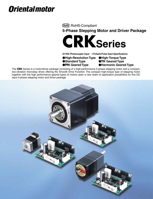
RoHS-Compliant<br />
5-Phase Stepping <strong>Motor</strong> and Driver Package<br />
<strong>CRK</strong><strong>Series</strong><br />
24 VDC Photocoupler Input 1-Pulse/2-Pulse Input Specifications<br />
High-Resolution Type<br />
Standard Type<br />
PN Geared Type<br />
High-Torque Type<br />
TH Geared Type<br />
Harmonic Geared Type<br />
The <strong>CRK</strong> <strong>Series</strong> is a motor/driver package consisting of a high-performance 5-phase stepping motor and a compact,<br />
low-vibration microstep driver offering the Smooth Drive Function. The compact high-torque type of stepping motor<br />
together with the high performance geared types of motors open a new realm of application possibilities for this DC<br />
input 5-phase stepping motor and driver package.
RoHS-Compliant<br />
5-Phase Stepping <strong>Motor</strong> and Driver Package<br />
<strong>CRK</strong> <strong>Series</strong><br />
The <strong>CRK</strong> <strong>Series</strong> is a motor/driver unit combining a<br />
high-performance, 5-phase stepping motor with a<br />
compact, low-vibration microstep driver offering the<br />
Smooth Drive Function. Four frame sizes of 20 mm<br />
(0.79 in.), 28 mm (1.10 in.), 42 mm (1.65 in.) and<br />
60 mm (2.36 in.) are available, and there are models<br />
fi tted with various geared motors.<br />
Features<br />
Newly Designed <strong>Motor</strong>s<br />
High-Resolution <strong>Motor</strong><br />
· Improved Stopping Accuracy<br />
The basic step angle of the high-resolution type is 0.36˚/step, which<br />
is half the basic step angle of the standard type.<br />
The positioning accuracy of stepping motors is affected by frictional<br />
load.<br />
The <strong>CRK</strong>'s high-resolution type, having a smaller basic step angle<br />
and capable of generating approx. 1.5 times the torque of the<br />
standard type, ensures quick torque rise, thereby minimizing the<br />
effect of frictional load.<br />
Comparison of Angle-Torque Characteristics<br />
1.5 Torque<br />
TH2<br />
1<br />
TH1<br />
0.5<br />
TL<br />
0<br />
-1.8 -0.9 0.9 1.8 Angle [deg]<br />
-0.5<br />
-1<br />
-1.5<br />
-TL<br />
TL: Friction Torque<br />
TH1,TH2: Maximum Holding Torque<br />
High-Resolution Type<br />
Standard Type<br />
TH1: <strong>CRK</strong>566AP (Standard Type)<br />
TH2: <strong>CRK</strong>566PMAP (High-Resolution Type)<br />
· Static Angle Error of 2 Arc Minutes (No Load)<br />
The high-resolution type is designed with a static angle error of 2 arc<br />
minutes (0.034˚) [standard type: 3 arc minutes (0.05˚)]. The reduced<br />
error helps improve the positioning accuracy of your equipment.<br />
Angle Error [deg]<br />
Static Angle Characteristics<br />
Power Supply Voltage: 24 VDC<br />
Resolution 1 (0.36˚/step)<br />
0.06<br />
0.05<br />
0.04<br />
0.03<br />
0.02<br />
0.01<br />
0<br />
<strong>CRK</strong>566PMBP<br />
-0.01<br />
-0.02<br />
-0.03<br />
-0.04<br />
-0.05<br />
-0.06<br />
0 60 120 180 240 300 360<br />
Angle [deg]<br />
High-Torque <strong>Motor</strong><br />
The high-resolution type and high-torque type adopt a newly<br />
designed high-torque motor that widens the range of applications.<br />
The smaller motor allows for compact equipment design.<br />
The motor current is reduced to suppress heat generation.<br />
Example) Avoidance of temperature rise in precision equipment or<br />
machinery<br />
Torque [oz-in]<br />
200<br />
150<br />
100<br />
50<br />
Torque [N·m]<br />
Comparison of Speed vs. Torque Characteristics<br />
Current: 1.4A/Phase Step Angle: 0.36˚/step<br />
With Damper D6CL-8.0F: JL=14010 7 kg·m 2 (0.77 oz-in 2 )<br />
1.6<br />
1.2<br />
0.8<br />
0.4<br />
<strong>CRK</strong>566PMBP<br />
(High-Resolution Type)<br />
<strong>CRK</strong>566BP<br />
(Standard Type)<br />
0<br />
0<br />
0 100 200 300 400 500 600 700 800 900 1000<br />
Speed [r/min]<br />
2
Connector Coupling Design<br />
The high-resolution type and high-torque type adopt a<br />
connector-coupled motor to ensure greater ease of handling.<br />
There is no need to cut lead wires or pressure-bond the connector.<br />
You can also select a cable of desired length and type.<br />
The connector coupling design also makes maintenance easy.<br />
✽The <strong>CRK</strong> package comes with a motor leadwire/connector assembly<br />
[0.6 m (2 ft.)].<br />
Wide Range of <strong>Motor</strong> Variations<br />
The <strong>CRK</strong> <strong>Series</strong> offers models of the high-resolution type,<br />
high-torque type and standard type, as well as various geared types.<br />
You can find a product meeting your specific torque, resolution or<br />
other needs from a total of 98 different specifications.<br />
Smooth Drive Function for Enhanced Ease of Use<br />
The Smooth Drive Function automatically controls operations via<br />
microstep drive at the same travel distance and speed used in<br />
the full-step mode, without requiring the operator to change the<br />
pulse input settings.<br />
This function is particularly useful when the <strong>CRK</strong> <strong>Series</strong> is used in<br />
the full-step or half-step mode.<br />
Vibration Component Voltage Vp-p [V]<br />
2.0<br />
1.6<br />
1.2<br />
0.8<br />
0.4<br />
Comparison of Vibration Characteristics<br />
CSK566-NATA 0.72˚/step (Conventional Model)<br />
<strong>CRK</strong>566PMAP 0.36˚/step Smooth Drive Function: ON<br />
0 0 100 200 300 400<br />
Speed [r/min]<br />
Compact Size<br />
The compact, lightweight driver in the <strong>CRK</strong> <strong>Series</strong> is approx. 45%<br />
smaller than a conventional full-step driver.<br />
Compact, Lightweight Microstep Driver<br />
The driver in the <strong>CRK</strong> <strong>Series</strong> achieves microstep drive in a compact,<br />
lightweight body.<br />
A new IC allows the driver to provide various functions, including the<br />
following:<br />
Smooth Drive Function<br />
1-pulse/2-pulse input mode switching<br />
25 preset step angles<br />
Power LED<br />
Photocoupler input<br />
77 mm (3.03 in.)<br />
Mass: 140 g (0.31 lb.)<br />
Comparison of Driver Size and Weights<br />
72 mm (2.83 in.)<br />
Conventional Model (CSD58N-T)<br />
Mass: 40 g (0.088 lb.)<br />
65 mm (2.56 in.)<br />
New Product (CRD51P)<br />
45 mm (1.77 in.)<br />
25 mm<br />
(0.98 in.)<br />
Mass: 40 g (0.088 lb.)<br />
Conforming to International Safety Standards<br />
The <strong>CRK</strong> <strong>Series</strong> is UL-recognized and CSA-certified.<br />
It also bears the CE Mark as a proof of conformance to the EMC<br />
Directives.<br />
Safe operation is ensured anywhere in the world.<br />
45 mm<br />
(1.77 in.)<br />
65 mm<br />
(2.56 in.)<br />
Lower Vibration and Noise Achieved by Microstep Drive<br />
The basic step angle of the motor can be divided into a<br />
maximum of 250 microstep angles without using any mechanical<br />
element such as a reduction gear.<br />
As a result, vibration and noise are further reduced.<br />
RoHS-Compliant<br />
The <strong>CRK</strong> <strong>Series</strong> conforms to the RoHS Directive that prohibits the<br />
use of six chemical substances including lead and cadmium.<br />
RoHS (Restriction of Hazardous Substances) Directive:<br />
Directive on restriction of the use of certain hazardous substances in electrical<br />
and electronic equipment (2002/95/EC).<br />
The RoHs Directive prohibits the use of six chemical substances in electrical<br />
and electronic products sold in the EU member states. The six controlled<br />
substances are: lead, hexavalent chromium, cadmium, mercury and two<br />
specific brominated flame-retardants (PBB and PBDE).<br />
Improved 5-Phase Performance can Usually be Easily<br />
Integrated into an Existing 2-Phase System<br />
The basic step angle can be adjusted to match a 2-phase<br />
stepping motor's step angles, so a switchover from the 2-phase<br />
microstep mode can be easily made, without having to change<br />
input pulses.<br />
3
Wide Variety<br />
The <strong>CRK</strong> <strong>Series</strong> comes in four frame sizes of 20 to 60 mm (0.79 to 2.36 in.), as well as three geared types. You can choose from as many as 98<br />
different specifications to suit your specific needs.<br />
Type Features 20 mm (0.79 in.) 28 mm (1.10 in.) 42 mm (1.65 in.) 60 mm (2.36 in.) Driver<br />
High-Resolution Type<br />
A high-torque motor<br />
offering higher<br />
positioning accuracy<br />
with the basic step angle<br />
set to 0.36˚/step, or half<br />
the basic step angle of<br />
the standard type.<br />
High-Torque Type<br />
A high-torque motor<br />
generating high<br />
torque of approx.<br />
1.3 to 1.5 times the<br />
level achieved by the<br />
standard type.<br />
Standard Type<br />
The basic model in the<br />
<strong>CRK</strong> <strong>Series</strong> offering<br />
an optimal balance of<br />
torque, low vibration<br />
and low noise.<br />
Low Backlash Type<br />
TH Geared Type<br />
A geared motor<br />
achieving both low<br />
backlash and low cost.<br />
Non-Backlash Type<br />
PN Geared Type<br />
Harmonic<br />
Geared Type<br />
A high-accuracy geared<br />
motor achieving a<br />
backlash of 3 arc<br />
minutes or less. It also<br />
provides high strength<br />
and wide gear ratios.<br />
A high-accuracy,<br />
backlash-free geared<br />
motor adopting a newly<br />
developed harmonic<br />
gear. It ensures high<br />
strength in a compact<br />
body.<br />
4
Characteristics Comparison for Geared <strong>Motor</strong>s<br />
Geared Type<br />
Features<br />
Permissible Torque/<br />
Maximum Torque<br />
[N·m (lb-in)]<br />
Backlash<br />
[arc min]<br />
Basic<br />
Resolution<br />
[deg/step]<br />
Output Shaft<br />
Speed [r/min]<br />
Non-Backlash Type Low Backlash Type<br />
TH Geared (Parallel Shaft)<br />
PN Geared (Planetary Gear)<br />
Harmonic Geared<br />
(Harmonic Drive)<br />
· A wide variety of low gear ratios for high-speed<br />
operation<br />
· Gear ratios:<br />
1:3.6, 1:7.2, 1:10, 1:20, 1:30<br />
· High speed (low gear ratio), high positioning precision<br />
· High permissible/maximum torque<br />
· A wide variety of gear ratios for selecting the<br />
desired step angle<br />
· Centered output shaft<br />
· Gear ratios:<br />
1:5, 1:7.2, 1:10, 1:25, 1:36, 1:50<br />
· High positioning precision<br />
· High permissible/maximum torque<br />
· High gear ratio, high resolution<br />
· Centered output shaft<br />
· Gear ratios:<br />
1:50, 1:100<br />
4 (35)<br />
Permissible Maximum<br />
Torque Torque<br />
8 (70) 20 (177) 3<br />
Permissible Maximum<br />
Torque Torque<br />
8 (70) 28 (240) 0<br />
60<br />
0.0072<br />
0.0144<br />
0.024<br />
70<br />
500<br />
600<br />
Note:<br />
The values shown above must be used as reference.<br />
The actual values vary depending on the motor frame size and gear ratio.<br />
Safety Standards and CE Marking<br />
<strong>Motor</strong><br />
High-Resolution Type<br />
High-Torque Type<br />
Standard Type<br />
TH Geared Type<br />
PN Geared Type<br />
Harmonic Geared Type<br />
Product Applicable Standards ✽3 Certification Body Standards File No. CE Marking<br />
UL 60950-1<br />
CSA C22.2 No.60950-1<br />
UL 60950<br />
CSA C22.2 No.60950<br />
20 mm (0.79 in.) ✽1<br />
UL 60950<br />
UL<br />
28 mm (1.10 in.) ✽2 CSA C22.2 No.60950<br />
42 mm (1.65 in.) UL 1004, UL 2111 UL<br />
60 mm (2.36 in.)<br />
UL 1004, UL 2111<br />
CSA C22.2 No.77<br />
CSA C22.2 No.100<br />
UL<br />
UL<br />
UL<br />
E208200<br />
E208200<br />
E64199<br />
EMC Directive ✽4<br />
Driver<br />
UL 60950-1<br />
CSA C22.2 No.60950-1<br />
UL E208200<br />
✽1 Harmonic geared type only<br />
✽2 TH geared type and PN geared type only<br />
✽3 Approval conditions for UL 60950, UL 60950-1: Class 3 equipment, SELV circuit, Pollution degree 2<br />
✽4 <strong>Oriental</strong> <strong>Motor</strong> declares compliance with the EMC Directive based on motor and driver combinations.<br />
When the system is approved under various safety standards, the model names in the motor and driver nameplates are the approved model names.<br />
List of <strong>Motor</strong> and Driver Combinations ➜ Page 31<br />
The EMC value changes according to the wiring and layout. Therefore, the final EMC level must be checked with the motor/driver incorporated in the user's equipment.<br />
5
System Configuration<br />
An example of a system configuration with the SG8030 <strong>Series</strong> controller.<br />
<strong>Motor</strong> Mounting Brackets (Accessories)<br />
A motor of the high-resolution type [excluding<br />
□28 mm (□1.10 in.) motors], high-torque<br />
type [excluding □20/28 mm (□0.79/1.10 in.)<br />
motors], standard type or geared type<br />
[excluding □28 mm (□1.10 in.) TH geared,<br />
PN geared motors or harmonic geared<br />
motors] can be installed easily.<br />
(➜ Page 33)<br />
Driver Leadwire Set (Accessories)<br />
The driver leadwire set includes<br />
three sets of leadwires, for<br />
connection between the driver<br />
and motor, power supply and<br />
I/O signal. A connector for onetouch<br />
connection with <strong>CRK</strong><br />
<strong>Series</strong> driver is assembled at<br />
one end of the leadwire.<br />
(➜ Page 40)<br />
Flexible Couplings<br />
(Accessories)<br />
Non-backlash coupling for<br />
precise positioning<br />
(➜ Page 36)<br />
<strong>Motor</strong><br />
<strong>CRK</strong> <strong>Series</strong><br />
Driver<br />
Controller<br />
(Sold separately)<br />
(➜ Page 32)<br />
Programmable<br />
Controller<br />
(Not supplied)<br />
Clean Dampers (Accessories)<br />
Effective to suppress stepping motor<br />
vibration and improve high-speed<br />
performance [excluding □20 mm<br />
(□0.79 in.) motors].<br />
(➜ Page 39)<br />
24 VDC<br />
Power<br />
Supply<br />
(Not supplied)<br />
Example of System Configuration<br />
(Body)<br />
<strong>CRK</strong> <strong>Series</strong><br />
<strong>CRK</strong>566PMBP<br />
<br />
(Sold separately)<br />
Controller<br />
SG8030J-U<br />
: Required under this system.<br />
: Optional accessory offered by <strong>Oriental</strong> <strong>Motor</strong>.<br />
<strong>Motor</strong> Mounting<br />
Bracket<br />
PAL2P-5<br />
Flexible<br />
Coupling<br />
MCS300808<br />
Clean Damper<br />
D6CL-8.0F<br />
Driver Leadwire Set<br />
[0.6 m (2 ft.)]<br />
LCS04SD5<br />
The system configuration shown above is an example. Other combinations are available.<br />
6
Product Number Code<br />
High-Resolution Type/High-Torque Type/Standard Type<br />
q w e r t y u i<br />
Geared Type<br />
q<br />
w<br />
e<br />
r<br />
t<br />
y<br />
u<br />
i<br />
<strong>Series</strong> <strong>CRK</strong>: <strong>CRK</strong> <strong>Series</strong><br />
5: 5-Phase<br />
<strong>Motor</strong> Frame Size 1: 20 mm (0.79 in.) 2: 28 mm (1.10 in.)<br />
4: 42 mm (1.65 in.) 6: 60 mm (2.36 in.)<br />
<strong>Motor</strong> Case Length<br />
<strong>Motor</strong> Type<br />
Resolution M: High-Resolution<br />
<strong>Motor</strong> Shaft Type A: Single Shaft B: Double Shaft<br />
Signal I/O Mode of Driver P: Photocoupler<br />
q w e r t y u i o<br />
Product Line<br />
q<br />
w<br />
e<br />
r<br />
t<br />
y<br />
u<br />
i<br />
o<br />
<strong>Series</strong> <strong>CRK</strong>: <strong>CRK</strong> <strong>Series</strong><br />
5: 5-Phase<br />
<strong>Motor</strong> Frame Size 2: 28 mm (1.10 in.) 4: 42 mm (1.65 in.)<br />
6: 60 mm (2.36 in.)<br />
<strong>Motor</strong> Case Length<br />
<strong>Motor</strong> Type<br />
<strong>Motor</strong> Shaft Type A: Single Shaft B: Double Shaft<br />
Signal I/O Mode of Driver P: Photocoupler<br />
Gearhead Type T: TH Geared Type N: PN Geared Type<br />
H: Harmonic Geared Type<br />
Gear Ratio<br />
High-Resolution Type<br />
TH Geared Type<br />
Model (Single Shaft)<br />
Model (Double Shaft)<br />
Model (Single Shaft)<br />
Model (Double Shaft)<br />
<strong>CRK</strong>523PMAP<br />
<strong>CRK</strong>523PMBP<br />
<strong>CRK</strong>523PAP-T7.2<br />
<strong>CRK</strong>523PBP-T7.2<br />
<strong>CRK</strong>524PMAP<br />
<strong>CRK</strong>524PMBP<br />
<strong>CRK</strong>523PAP-T10<br />
<strong>CRK</strong>523PBP-T10<br />
<strong>CRK</strong>525PMAP<br />
<strong>CRK</strong>525PMBP<br />
<strong>CRK</strong>523PAP-T20<br />
<strong>CRK</strong>523PBP-T20<br />
<strong>CRK</strong>544PMAP<br />
<strong>CRK</strong>544PMBP<br />
<strong>CRK</strong>523PAP-T30<br />
<strong>CRK</strong>523PBP-T30<br />
<strong>CRK</strong>546PMAP<br />
<strong>CRK</strong>546PMBP<br />
<strong>CRK</strong>543AP-T3.6<br />
<strong>CRK</strong>543BP-T3.6<br />
<strong>CRK</strong>564PMAP<br />
<strong>CRK</strong>564PMBP<br />
<strong>CRK</strong>543AP-T7.2<br />
<strong>CRK</strong>543BP-T7.2<br />
<strong>CRK</strong>566PMAP<br />
<strong>CRK</strong>566PMBP<br />
<strong>CRK</strong>543AP-T10<br />
<strong>CRK</strong>543BP-T10<br />
<strong>CRK</strong>569PMAP<br />
<strong>CRK</strong>569PMBP<br />
<strong>CRK</strong>543AP-T20<br />
<strong>CRK</strong>543BP-T20<br />
<strong>CRK</strong>543AP-T30<br />
<strong>CRK</strong>543BP-T30<br />
High-Torque Type<br />
<strong>CRK</strong>564AP-T3.6<br />
<strong>CRK</strong>564AP-T7.2<br />
<strong>CRK</strong>564BP-T3.6<br />
<strong>CRK</strong>564BP-T7.2<br />
Model (Single Shaft)<br />
<strong>CRK</strong>513PAP<br />
<strong>CRK</strong>523PAP<br />
Model (Double Shaft)<br />
<strong>CRK</strong>513PBP<br />
<strong>CRK</strong>523PBP<br />
<strong>CRK</strong>564AP-T10<br />
<strong>CRK</strong>564AP-T20<br />
<strong>CRK</strong>564AP-T30<br />
<strong>CRK</strong>564BP-T10<br />
<strong>CRK</strong>564BP-T20<br />
<strong>CRK</strong>564BP-T30<br />
<strong>CRK</strong>525PAP<br />
<strong>CRK</strong>525PBP<br />
<strong>CRK</strong>544PAP<br />
<strong>CRK</strong>544PBP<br />
<strong>CRK</strong>546PAP<br />
<strong>CRK</strong>546PBP<br />
PN Geared Type<br />
Standard Type<br />
Model (Single Shaft)<br />
<strong>CRK</strong>543AP<br />
<strong>CRK</strong>544AP<br />
<strong>CRK</strong>545AP<br />
<strong>CRK</strong>564AP<br />
<strong>CRK</strong>566AP<br />
<strong>CRK</strong>569AP<br />
Model (Double Shaft)<br />
<strong>CRK</strong>543BP<br />
<strong>CRK</strong>544BP<br />
<strong>CRK</strong>545BP<br />
<strong>CRK</strong>564BP<br />
<strong>CRK</strong>566BP<br />
<strong>CRK</strong>569BP<br />
Model (Single Shaft)<br />
<strong>CRK</strong>523PAP-N5<br />
<strong>CRK</strong>523PAP-N7.2<br />
<strong>CRK</strong>523PAP-N10<br />
<strong>CRK</strong>544AP-N5<br />
<strong>CRK</strong>544AP-N7.2<br />
<strong>CRK</strong>544AP-N10<br />
<strong>CRK</strong>566AP-N5<br />
<strong>CRK</strong>566AP-N7.2<br />
Model (Double Shaft)<br />
<strong>CRK</strong>523PBP-N5<br />
<strong>CRK</strong>523PBP-N7.2<br />
<strong>CRK</strong>523PBP-N10<br />
<strong>CRK</strong>544BP-N5<br />
<strong>CRK</strong>544BP-N7.2<br />
<strong>CRK</strong>544BP-N10<br />
<strong>CRK</strong>566BP-N5<br />
<strong>CRK</strong>566BP-N7.2<br />
<strong>CRK</strong>566AP-N10<br />
<strong>CRK</strong>566BP-N10<br />
<strong>CRK</strong>564AP-N25<br />
<strong>CRK</strong>564BP-N25<br />
<strong>CRK</strong>564AP-N36<br />
<strong>CRK</strong>564BP-N36<br />
<strong>CRK</strong>564AP-N50<br />
<strong>CRK</strong>564BP-N50<br />
Harmonic Geared Type<br />
Model (Single Shaft)<br />
Model (Double Shaft)<br />
<strong>CRK</strong>543AP-H50<br />
<strong>CRK</strong>543BP-H50<br />
<strong>CRK</strong>543AP-H100<br />
<strong>CRK</strong>543BP-H100<br />
<strong>CRK</strong>564AP-H50<br />
<strong>CRK</strong>564BP-H50<br />
<strong>CRK</strong>564AP-H100<br />
<strong>CRK</strong>564BP-H100<br />
7
High-Resolution Type <strong>Motor</strong> Frame Size 28 mm (1.10 in.), 42 mm (1.65 in.)<br />
Specifications<br />
Model<br />
Single Shaft <strong>CRK</strong>523PMAP ✽ <strong>CRK</strong>524PMAP ✽ <strong>CRK</strong>525PMAP ✽ <strong>CRK</strong>544PMAP ✽ <strong>CRK</strong>546PMAP ✽<br />
Double Shaft <strong>CRK</strong>523PMBP ✽ <strong>CRK</strong>524PMBP ✽ <strong>CRK</strong>525PMBP ✽ <strong>CRK</strong>544PMBP ✽ <strong>CRK</strong>546PMBP ✽<br />
Maximum Holding Torque N·m (oz-in) 0.042 (5.9) 0.061 (8.6) 0.09 (12.7) 0.24 (34) 0.42 (59)<br />
Rotor Inertia J: kg·m 2 (oz-in 2 ) 910 -7 (0.049) 1310 -7 (0.071) 1910 -7 (0.104) 6010 -7 (0.33) 12110 -7 (0.66)<br />
Rated Current A/Phase 0.35 0.75<br />
Basic Step Angle 0.36˚<br />
Power Source 24 VDC10% 0.7 A 24 VDC10% 1.4 A<br />
Excitation Mode<br />
Microstep<br />
Mass<br />
<strong>Motor</strong> kg (lb.) 0.11 (0.24) 0.15 (0.33) 0.2 (0.44) 0.3 (0.66) 0.5 (1.1)<br />
Driver kg (lb.) 0.04 (0.088)<br />
Dimension No.<br />
<strong>Motor</strong> x c<br />
Driver ⁄5<br />
How to Read Specifications Table ➜ See the following descriptions.<br />
✽<strong>Motor</strong> leadwire/connector assembly [0.6 m (2 ft.)] is included with connector type package.<br />
Speed – Torque Characteristics<br />
fs: Maximum Starting Frequency<br />
<strong>CRK</strong>523PMAP/<strong>CRK</strong>523PMBP<br />
<strong>CRK</strong>524PMAP/<strong>CRK</strong>524PMBP<br />
<strong>CRK</strong>525PMAP/<strong>CRK</strong>525PMBP<br />
Current [A]<br />
0.6<br />
0.4<br />
0.2<br />
0<br />
Torque [oz-in]<br />
8<br />
6<br />
4<br />
2<br />
0<br />
Torque [N·m]<br />
Current: 0.35 A/Phase Step Angle: 0.36˚/step<br />
With Damper D4CL-5.0F: JL=3410 7 kg·m 2 (0.186 oz-in 2 )<br />
0.06<br />
0.05<br />
0.04<br />
Pullout Torque<br />
0.03<br />
0.02<br />
0.01<br />
0<br />
0<br />
0<br />
(0)<br />
fs<br />
Driver Input Current<br />
500 1000 1500 2000<br />
Speed [r/min]<br />
10<br />
(100)<br />
20<br />
(200)<br />
Pulse Speed [kHz]<br />
30 Resolution 1<br />
(300) (Resolution 10)<br />
Current [A]<br />
0.6<br />
0.4<br />
0.2<br />
0<br />
Torque [oz-in]<br />
10<br />
8<br />
6<br />
4<br />
2<br />
0<br />
Torque [N·m]<br />
Current: 0.35 A/Phase Step Angle: 0.36˚/step<br />
With Damper D4CL-5.0F: JL=3410 7 kg·m 2 (0.186 oz-in 2 )<br />
0.08<br />
0.07<br />
0.06<br />
0.05<br />
0.04<br />
0.03<br />
0.02<br />
0.01<br />
0<br />
0<br />
0<br />
(0)<br />
fs<br />
500 1000 1500 2000 2500<br />
Speed [r/min]<br />
10<br />
(100)<br />
Pullout Torque<br />
Driver Input Current<br />
20<br />
(200)<br />
Pulse Speed [kHz]<br />
30<br />
(300)<br />
40 Resolution 1<br />
(400) (Resolution 10)<br />
Current [A]<br />
0.6<br />
0.4<br />
0.2<br />
0<br />
Torque [oz-in]<br />
16<br />
12<br />
8<br />
4<br />
0<br />
Torque [N·m]<br />
Current: 0.35 A/Phase Step Angle: 0.36˚/step<br />
With Damper D4CL-5.0F: JL=3410 7 kg·m 2 (0.186 oz-in 2 )<br />
0.12<br />
0.10<br />
0.08<br />
Pullout Torque<br />
0.06<br />
0.04<br />
0.02<br />
0<br />
0<br />
0<br />
(0)<br />
fs<br />
Driver Input Current<br />
500 1000 1500 2000<br />
Speed [r/min]<br />
10<br />
(100)<br />
20<br />
(200)<br />
Pulse Speed [kHz]<br />
30<br />
(300)<br />
Resolution 1<br />
(Resolution 10)<br />
<strong>CRK</strong>544PMAP/<strong>CRK</strong>544PMBP<br />
<strong>CRK</strong>546PMAP/<strong>CRK</strong>546PMBP<br />
Current [A]<br />
1.0<br />
0.5<br />
0<br />
Torque [oz-in]<br />
40<br />
30<br />
20<br />
10<br />
0<br />
Torque [N·m]<br />
Current: 0.75 A/Phase Step Angle: 0.36˚/step<br />
With Damper D4CL-5.0F: JL=3410 7 kg·m 2 (0.186 oz-in 2 )<br />
0.35<br />
0.30<br />
0.25<br />
0.20<br />
Pullout Torque<br />
0.15<br />
0.10<br />
0.05<br />
0<br />
0<br />
0<br />
(0)<br />
fs<br />
Driver Input Current<br />
200 400 600 800 1000<br />
Speed [r/min]<br />
5<br />
(50)<br />
10<br />
(100)<br />
Pulse Speed [kHz]<br />
15<br />
(150)<br />
Resolution 1<br />
(Resolution 10)<br />
Current [A]<br />
1.0<br />
0.5<br />
0<br />
Torque [oz-in]<br />
80<br />
60<br />
40<br />
20<br />
0<br />
Torque [N·m]<br />
Current: 0.75 A/Phase Step Angle: 0.36˚/step<br />
With Damper D4CL-5.0F: JL=3410 7 kg·m 2 (0.186 oz-in 2 )<br />
0.6<br />
0.5<br />
0.4<br />
Pullout Torque<br />
0.3<br />
0.2<br />
0.1<br />
0<br />
0<br />
0<br />
(0)<br />
Driver Input Current<br />
fs<br />
200 400 600 800 1000<br />
Speed [r/min]<br />
5<br />
(50)<br />
10<br />
(100)<br />
Pulse Speed [kHz]<br />
15<br />
(150)<br />
Resolution 1<br />
(Resolution 10)<br />
The pulse input circuit responds to approximately 500 kHz with a pulse duty of 50%.<br />
Notes:<br />
Pay attention to heat dissipation from motor as there will be a considerable amount of heat under certain conditions.<br />
Be sure to keep the temperature of the motor case under 100˚C (212˚F).<br />
[Under 75˚C (167˚F) is required to comply with UL or CSA standards.]<br />
When using the motor with the dedicated driver, the driver's automatic current cutback function at motor standstill reduces maximum holding torque by approximately 50%.<br />
How to Read Specifications Table Please read the following information before examining the specifications on pages 8 to 18.<br />
Maximum Holding Torque: The holding torque (5-Phase: 5-Phase Excitation) is the maximum holding power (torque) the stepping motor has when power (rated current)<br />
is being supplied but the motor is not rotating (with consideration given to the permissible strength of the gear when applicable). At motor<br />
standstill, the driver's "Automatic Current Cutback" function reduces the maximum holding torque by approximately 50%.<br />
Permissible Torque:<br />
Maximum Torque:<br />
Angle Error:<br />
The permissible torque represents the torque value limited by the mechanical strength of the gear when operated at a constant speed. For the<br />
types excluding PN and harmonic geared type, the total torque including acceleration/deceleration torque should not exceed this value.<br />
This is the maximum torque that can be used instantaneously (for a short time). During acceleration/deceleration, the motor can be operated up<br />
to this value. (PN geared, harmonic geared type only)<br />
Difference between the theoretical angle of rotation of the output shaft as calculated from the input pulses, and the actual angle of rotation.<br />
(PN geared type only)<br />
8
High-Resolution Type <strong>Motor</strong> Frame Size 60 mm (2.36 in.)<br />
Specifications<br />
Model<br />
Single Shaft <strong>CRK</strong>564PMAP ✽ <strong>CRK</strong>566PMAP ✽ <strong>CRK</strong>569PMAP ✽<br />
Double Shaft <strong>CRK</strong>564PMBP ✽ <strong>CRK</strong>566PMBP ✽ <strong>CRK</strong>569PMBP ✽<br />
Maximum Holding Torque N·m (oz-in) 0.78 (110) 1.3 (184) 2.3 (320)<br />
Rotor Inertia J: kg·m 2 (oz-in 2 ) 31010 -7 (1.7) 49010 -7 (2.7) 97010 -7 (5.3)<br />
Rated Current A/Phase 1.4<br />
Basic Step Angle 0.36˚<br />
Power Source 24 VDC10% 2.5 A<br />
Excitation Mode<br />
Microstep<br />
Mass<br />
<strong>Motor</strong> kg (lb.) 0.65 (1.43) 0.87 (1.91) 1.5 (3.3)<br />
Driver kg (lb.) 0.04 (0.088)<br />
Dimension No.<br />
<strong>Motor</strong><br />
v<br />
Driver ⁄5<br />
How to Read Specifications Table ➜ Page 8<br />
✽<strong>Motor</strong> leadwire/connector assembly [0.6 m (2 ft.)] is included with connector type package.<br />
Speed – Torque Characteristics<br />
fs: Maximum Starting Frequency<br />
<strong>CRK</strong>564PMAP/<strong>CRK</strong>564PMBP<br />
Current [A]<br />
2<br />
1<br />
0<br />
Torque [oz-in]<br />
120<br />
80<br />
40<br />
0<br />
Torque [N·m]<br />
Current: 1.4 A/Phase Step Angle: 0.36˚/step<br />
With Damper D6CL-8.0F: JL=14010 7 kg·m 2 (0.77 oz-in 2 )<br />
1.0<br />
0.8<br />
0.6<br />
0.4<br />
0.2<br />
0<br />
0<br />
0<br />
(0)<br />
Driver Input Current<br />
fs<br />
200 400 600 800 1000<br />
Speed [r/min]<br />
5<br />
(50)<br />
Pullout Torque<br />
10<br />
(100)<br />
Pulse Speed [kHz]<br />
15<br />
(150)<br />
Resolution 1<br />
(Resolution 10)<br />
<strong>CRK</strong>566PMAP/<strong>CRK</strong>566PMBP<br />
Current [A]<br />
4<br />
2<br />
0<br />
Torque [oz-in]<br />
200<br />
150<br />
100<br />
50<br />
0<br />
Torque [N·m]<br />
Current: 1.4 A/Phase Step Angle: 0.36˚/step<br />
With Damper D6CL-8.0F: JL=14010 7 kg·m 2 (0.77 oz-in 2 )<br />
1.6<br />
1.2<br />
0.8<br />
0.4<br />
0<br />
0<br />
0<br />
(0)<br />
Driver Input Current<br />
2.5<br />
(25)<br />
Pullout Torque<br />
fs<br />
100 200 300 400 500 600<br />
Speed [r/min]<br />
5<br />
(50)<br />
Pulse Speed [kHz]<br />
7.5<br />
(75)<br />
10 Resolution 1<br />
(100) (Resolution 10)<br />
<strong>CRK</strong>569PMAP/<strong>CRK</strong>569PMBP<br />
Current [A]<br />
3<br />
2<br />
1<br />
0<br />
Torque [oz-in]<br />
400<br />
300<br />
200<br />
100<br />
0<br />
Torque [N·m]<br />
Current: 1.4 A/Phase Step Angle: 0.36˚/step<br />
With Damper D6CL-8.0F: JL=14010 7 kg·m 2 (0.77 oz-in 2 )<br />
3.0<br />
2.5<br />
2.0<br />
1.5<br />
1.0<br />
0.5<br />
0<br />
0<br />
0<br />
(0)<br />
Driver Input Current<br />
fs<br />
50 100 150 200 250 300 350<br />
Speed [r/min]<br />
1<br />
(10)<br />
2<br />
(20)<br />
Pullout Torque<br />
3<br />
(30)<br />
Pulse Speed [kHz]<br />
4<br />
(40)<br />
5<br />
(50)<br />
Resolution 1<br />
(Resolution 10)<br />
The pulse input circuit responds to approximately 500 kHz with a pulse duty of 50%.<br />
Notes:<br />
Pay attention to heat dissipation from motor as there will be a considerable amount of heat under certain conditions.<br />
Be sure to keep the temperature of the motor case under 100˚C (212˚F).<br />
[Under 75˚C (167˚F) is required to comply with UL or CSA standards.]<br />
When using the motor with the dedicated driver, the driver's automatic current cutback function at motor standstill reduces maximum holding torque by approximately 50%.<br />
9
High-Torque Type <strong>Motor</strong> Frame Size 20 mm (0.79 in.), 28 mm (1.10 in.)<br />
Specifications<br />
Model<br />
Single Shaft <strong>CRK</strong>513PAP ✽ <strong>CRK</strong>523PAP ✽ <strong>CRK</strong>525PAP ✽<br />
Double Shaft <strong>CRK</strong>513PBP ✽ <strong>CRK</strong>523PBP ✽ <strong>CRK</strong>525PBP ✽<br />
Maximum Holding Torque N·m (oz-in) 0.0231 (3.2) 0.048 (6.8) 0.078 (11)<br />
Rotor Inertia J: kg·m 2 (oz-in 2 ) 2.610 -7 (0.0142) 910 -7 (0.049) 1810 -7 (0.098)<br />
Rated Current A/Phase 0.35<br />
Basic Step Angle 0.72˚<br />
Power Source 24 VDC10% 0.7 A<br />
Excitation Mode<br />
Microstep<br />
Mass<br />
<strong>Motor</strong> kg (lb.) 0.05 (0.11) 0.11 (0.24) 0.2 (0.44)<br />
Driver kg (lb.) 0.04 (0.088)<br />
Dimension No.<br />
<strong>Motor</strong> z x<br />
Driver ⁄5<br />
How to Read Specifications Table ➜ Page 8<br />
✽<strong>Motor</strong> leadwire/connector assembly [0.6 m (2 ft.)] is included with connector type package.<br />
Speed – Torque Characteristics<br />
<strong>CRK</strong>513PAP/<strong>CRK</strong>513PBP<br />
Current [A]<br />
1.0<br />
0.5<br />
0<br />
Torque [oz-in]<br />
4<br />
3<br />
2<br />
1<br />
0<br />
Torque [N·m]<br />
Current: 0.35 A/Phase Step Angle: 0.72˚/step<br />
Load Inertia: JL=0 kg·m 2<br />
0.030<br />
0.025<br />
0.020<br />
0.015<br />
0.010<br />
0.005<br />
0<br />
0<br />
0<br />
(0)<br />
10<br />
(100)<br />
<strong>CRK</strong>525PAP/<strong>CRK</strong>525PBP<br />
14<br />
Pullout Torque<br />
fs<br />
Driver Input Current<br />
1000 2000 3000 4000<br />
Speed [r/min]<br />
20<br />
(200)<br />
Pulse Speed [kHz]<br />
30<br />
(300)<br />
Current: 0.35 A/Phase Step Angle: 0.72˚/step<br />
With Damper D4CL-5.0F: JL=3410 7 kg·m 2 (0.186 oz-in 2 )<br />
0.10<br />
Resolution 1<br />
(Resolution 10)<br />
fs: Maximum Starting Frequency<br />
<strong>CRK</strong>523PAP/<strong>CRK</strong>523PBP<br />
Current [A]<br />
1.0<br />
0.5<br />
0<br />
Torque [oz-in]<br />
8<br />
6<br />
4<br />
2<br />
0<br />
Torque [N·m]<br />
Current: 0.35 A/Phase Step Angle: 0.72˚/step<br />
With Damper D4CL-5.0F: JL=3410 7 kg·m 2 (0.186 oz-in 2 )<br />
0.06<br />
0.05<br />
0.04<br />
0.03<br />
0.02<br />
0.01<br />
fs<br />
0<br />
0<br />
0<br />
(0)<br />
Driver Input Current<br />
10<br />
(100)<br />
Pullout Torque<br />
1000 2000 3000 4000<br />
Speed [r/min]<br />
20<br />
(200)<br />
Pulse Speed [kHz]<br />
30<br />
(300)<br />
Resolution 1<br />
(Resolution 10)<br />
Current [A]<br />
2<br />
1<br />
0<br />
Torque [oz-in]<br />
12<br />
10<br />
8<br />
6<br />
4<br />
2<br />
0<br />
Torque [N·m]<br />
0.08<br />
0.06<br />
0.04<br />
0.02<br />
0<br />
0<br />
0<br />
(0)<br />
Driver Input Current<br />
fs<br />
1000 2000 3000 4000<br />
Speed [r/min]<br />
10<br />
(100)<br />
Pullout Torque<br />
20<br />
(200)<br />
Pulse Speed [kHz]<br />
30<br />
(300)<br />
Resolution 1<br />
(Resolution 10)<br />
The pulse input circuit responds to approximately 500 kHz with a pulse duty of 50%.<br />
Notes:<br />
Pay attention to heat dissipation from motor as there will be a considerable amount of heat under certain conditions.<br />
Be sure to keep the temperature of the motor case under 100˚C (212˚F).<br />
[Under 75˚C (167˚F) is required to comply with UL or CSA standards.]<br />
When using the motor with the dedicated driver, the driver's automatic current cutback function at motor standstill reduces maximum holding torque by approximately 50%.<br />
10
Standard/High-Torque Type <strong>Motor</strong> Frame Size 42 mm (1.65 in.)<br />
Specifications<br />
Model<br />
Single Shaft <strong>CRK</strong>543AP <strong>CRK</strong>544AP <strong>CRK</strong>545AP <strong>CRK</strong>544PAP ✽ <strong>CRK</strong>546PAP ✽<br />
Double Shaft <strong>CRK</strong>543BP <strong>CRK</strong>544BP <strong>CRK</strong>545BP <strong>CRK</strong>544PBP ✽ <strong>CRK</strong>546PBP ✽<br />
Maximum Holding Torque N·m (oz-in) 0.13 (18.4) 0.18 (25) 0.24 (34) 0.24 (34) 0.42 (59)<br />
Rotor Inertia J: kg·m 2 (oz-in 2 ) 3510 -7 (0.191) 5410 -7 (0.3) 6810 -7 (0.37) 5710 -7 (0.31) 11410 -7 (0.62)<br />
Rated Current A/Phase 0.75<br />
Basic Step Angle 0.72˚<br />
Power Source 24 VDC10% 1.4 A<br />
Excitation Mode<br />
Microstep<br />
Mass<br />
<strong>Motor</strong> kg (lb.) 0.21 (0.46) 0.27 (0.59) 0.35 (0.77) 0.3 (0.66) 0.5 (1.1)<br />
Driver kg (lb.) 0.04 (0.088)<br />
Dimension No.<br />
<strong>Motor</strong> b c<br />
Driver ⁄5<br />
How to Read Specifications Table ➜ Page 8<br />
✽<strong>Motor</strong> leadwire/connector assembly [0.6 m (2 ft.)] is included with connector type package.<br />
Speed – Torque Characteristics<br />
<strong>CRK</strong>543AP/<strong>CRK</strong>543BP<br />
Current [A]<br />
2<br />
1<br />
0<br />
Torque [oz-in]<br />
20<br />
15<br />
10<br />
5<br />
0<br />
Torque [N·m]<br />
Current: 0.75 A/Phase Step Angle: 0.72˚/step<br />
With Damper D4CL-5.0F: JL=3410 7 kg·m 2 (0.186 oz-in 2 )<br />
0.15<br />
0.10<br />
0.05<br />
0<br />
0<br />
0<br />
(0)<br />
fs<br />
1000 2000 3000 4000<br />
Speed [r/min]<br />
10<br />
(100)<br />
Pullout Torque<br />
Driver Input Current<br />
<strong>CRK</strong>545AP/<strong>CRK</strong>545BP<br />
Current [A]<br />
2<br />
1<br />
0<br />
Torque [oz-in]<br />
40<br />
30<br />
20<br />
10<br />
0<br />
Torque [N·m]<br />
20<br />
(200)<br />
Pulse Speed [kHz]<br />
30<br />
(300)<br />
Current: 0.75 A/Phase Step Angle: 0.72˚/step<br />
With Damper D4CL-5.0F: JL=3410 7 kg·m 2 (0.186 oz-in 2 )<br />
0.30<br />
0.25<br />
0.20<br />
0.15<br />
0.10<br />
0.05<br />
0<br />
0<br />
0<br />
(0)<br />
fs<br />
500 1000 1500 2000 2500<br />
Speed [r/min]<br />
5<br />
(50)<br />
Pullout Torque<br />
Driver Input Current<br />
10<br />
(100)<br />
Pulse Speed [kHz]<br />
<strong>CRK</strong>544PAP/<strong>CRK</strong>544PBP<br />
Current [A]<br />
2<br />
1<br />
0<br />
Torque [oz-in]<br />
40<br />
30<br />
20<br />
10<br />
0<br />
Torque [N·m]<br />
15<br />
(150)<br />
Current: 0.75 A/Phase Step Angle: 0.72˚/step<br />
With Damper D4CL-5.0F: JL=3410 7 kg·m 2 (0.186 oz-in 2 )<br />
0.30<br />
0.25<br />
0.20<br />
0.15<br />
0.10<br />
0.05<br />
0<br />
0<br />
0<br />
(0)<br />
5<br />
(50)<br />
Pullout Torque<br />
10<br />
(100)<br />
Pulse Speed [kHz]<br />
15<br />
(150)<br />
Resolution 1<br />
(Resolution 10)<br />
Resolution 1<br />
(Resolution 10)<br />
Driver Input Current<br />
fs<br />
500 1000 1500 2000 2500<br />
Speed [r/min]<br />
Resolution 1<br />
(Resolution 10)<br />
fs: Maximum Starting Frequency<br />
<strong>CRK</strong>544AP/<strong>CRK</strong>544BP<br />
Current [A]<br />
2<br />
1<br />
0<br />
Torque [oz-in]<br />
25<br />
20<br />
15<br />
10<br />
5<br />
0<br />
Torque [N·m]<br />
Current: 0.75 A/Phase Step Angle: 0.72˚/step<br />
With Damper D4CL-5.0F: JL=3410 7 kg·m 2 (0.186 oz-in 2 )<br />
0.20<br />
0.15<br />
0.10<br />
0.05<br />
0<br />
0<br />
0<br />
(0)<br />
fs<br />
500 1000 1500 2000 2500<br />
Speed [r/min]<br />
5<br />
(50)<br />
Pullout Torque<br />
Driver Input Current<br />
10<br />
(100)<br />
Pulse Speed [kHz]<br />
<strong>CRK</strong>546PAP/<strong>CRK</strong>546PBP<br />
Current [A]<br />
2<br />
1<br />
0<br />
Torque [oz-in]<br />
70<br />
60<br />
50<br />
40<br />
30<br />
20<br />
10<br />
0<br />
Torque [N·m]<br />
15<br />
(150)<br />
Current: 0.75 A/Phase Step Angle: 0.72˚/step<br />
With Damper D4CL-5.0F: JL=3410 7 kg·m 2 (0.186 oz-in 2 )<br />
0.5<br />
0.4<br />
0.3<br />
0.2<br />
0.1<br />
0<br />
0<br />
0<br />
(0)<br />
fs<br />
Pulse Speed [kHz]<br />
Resolution 1<br />
(Resolution 10)<br />
500 1000 1500 2000<br />
Speed [r/min]<br />
5<br />
(50)<br />
Pullout Torque<br />
Driver Input Current<br />
10<br />
(100)<br />
15<br />
(150)<br />
Resolution 1<br />
(Resolution 10)<br />
The pulse input circuit responds to approximately 500 kHz with a pulse duty of 50%.<br />
Notes:<br />
Pay attention to heat dissipation from motor as there will be a considerable amount of heat under certain conditions.<br />
Be sure to keep the temperature of the motor case under 100˚C (212˚F).<br />
[Under 75˚C (167˚F) is required to comply with UL or CSA standards.]<br />
When using the motor with the dedicated driver, the driver's automatic current cutback function at motor standstill reduces maximum holding torque by approximately 50%.<br />
11
Standard Type <strong>Motor</strong> Frame Size 60 mm (2.36 in.)<br />
Specifications<br />
Model<br />
Single Shaft <strong>CRK</strong>564AP <strong>CRK</strong>566AP <strong>CRK</strong>569AP<br />
Double Shaft <strong>CRK</strong>564BP <strong>CRK</strong>566BP <strong>CRK</strong>569BP<br />
Maximum Holding Torque N·m (oz-in) 0.42 (59) 0.83 (117) 1.66 (230)<br />
Rotor Inertia J: kg·m 2 (oz-in 2 ) 17510 -7 (0.96) 28010 -7 (1.53) 56010 -7 (3.1)<br />
Rated Current A/Phase 1.4<br />
Basic Step Angle 0.72˚<br />
Power Source 24 VDC10% 2.5 A<br />
Excitation Mode<br />
Microstep<br />
Mass<br />
<strong>Motor</strong> kg (lb.) 0.6 (1.32) 0.8 (1.76) 1.3 (2.9)<br />
Driver kg (lb.) 0.04 (0.088)<br />
Dimension No.<br />
<strong>Motor</strong><br />
n<br />
Driver ⁄5<br />
How to Read Specifications Table ➜ Page 8<br />
Speed – Torque Characteristics<br />
<strong>CRK</strong>564AP/<strong>CRK</strong>564BP<br />
Current [A]<br />
4<br />
2<br />
0<br />
Torque [oz-in]<br />
70<br />
60<br />
50<br />
40<br />
30<br />
20<br />
10<br />
0<br />
Torque [N·m]<br />
Current: 1.4 A/Phase Step Angle: 0.72˚/step<br />
With Damper D6CL-8.0F: JL=14010 7 kg·m 2 (0.77 oz-in 2 )<br />
0.5<br />
0.4<br />
0.3<br />
0.2<br />
0.1<br />
0<br />
0<br />
0<br />
(0)<br />
fs<br />
Driver Input Current<br />
500 1000 1500 2000 2500<br />
Speed [r/min]<br />
5<br />
(50)<br />
<strong>CRK</strong>569AP/<strong>CRK</strong>569BP<br />
Current [A]<br />
4<br />
2<br />
0<br />
Torque [oz-in]<br />
250<br />
200<br />
150<br />
100<br />
50<br />
0<br />
Torque [N·m]<br />
Pullout Torque<br />
10<br />
(100)<br />
Pulse Speed [kHz]<br />
15<br />
(150)<br />
Current: 1.4 A/Phase Step Angle: 0.72˚/step<br />
With Damper D6CL-8.0F: JL=14010 7 kg·m 2 (0.77 oz-in 2 )<br />
2.0<br />
1.5<br />
1.0<br />
0.5<br />
0<br />
0<br />
0<br />
(0)<br />
1<br />
(10)<br />
Pullout Torque<br />
2<br />
(20)<br />
Pulse Speed [kHz]<br />
Resolution 1<br />
(Resolution 10)<br />
Driver Input Current<br />
fs<br />
100 200 300 400 500<br />
Speed [r/min]<br />
3<br />
(30)<br />
4 Resolution 1<br />
(40) (Resolution 10)<br />
fs: Maximum Starting Frequency<br />
<strong>CRK</strong>566AP/<strong>CRK</strong>566BP<br />
Current [A]<br />
2<br />
1<br />
0<br />
Torque [oz-in]<br />
160<br />
120<br />
80<br />
40<br />
0<br />
Torque [N·m]<br />
Current: 1.4 A/Phase Step Angle: 0.72˚/step<br />
With Damper D6CL-8.0F: JL=14010 7 kg·m 2 (0.77 oz-in 2 )<br />
1.2<br />
1.0<br />
0.8<br />
0.6<br />
0.4<br />
0.2<br />
0<br />
0<br />
0<br />
(0)<br />
Driver Input Current<br />
fs<br />
200 400 600 800 1000<br />
Speed [r/min]<br />
2.5<br />
(25)<br />
Pullout Torque<br />
5<br />
(50)<br />
Pulse Speed [kHz]<br />
7.5 Resolution 1<br />
(75) (Resolution 10)<br />
The pulse input circuit responds to approximately 500 kHz with a pulse duty of 50%.<br />
Notes:<br />
Pay attention to heat dissipation from motor as there will be a considerable amount of heat under certain conditions.<br />
Be sure to keep the temperature of the motor case under 100˚C (212˚F).<br />
[Under 75˚C (167˚F) is required to comply with UL or CSA standards.]<br />
When using the motor with the dedicated driver, the driver's automatic current cutback function at motor standstill reduces maximum holding torque by approximately 50%.<br />
12
TH Geared Type <strong>Motor</strong> Frame Size 28 mm (1.10 in.)<br />
Specifications<br />
Model<br />
Single Shaft <strong>CRK</strong>523PAP-T7.2 ✽ <strong>CRK</strong>523PAP-T10 ✽ <strong>CRK</strong>523PAP-T20 ✽ <strong>CRK</strong>523PAP-T30 ✽<br />
Double Shaft <strong>CRK</strong>523PBP-T7.2 ✽ <strong>CRK</strong>523PBP-T10 ✽ <strong>CRK</strong>523PBP-T20 ✽ <strong>CRK</strong>523PBP-T30 ✽<br />
Maximum Holding Torque N·m (oz-in) 0.2 (28) 0.3 (42) 0.4 (56) 0.5 (71)<br />
Rotor Inertia J: kg·m 2 (oz-in 2 ) 910 -7 (0.049)<br />
Rated Current A/Phase 0.35<br />
Basic Step Angle 0.1˚ 0.072˚ 0.036˚ 0.024˚<br />
Gear Ratio 1 : 7.2 1 : 10 1 : 20 1 : 30<br />
Permissible Torque N·m (oz-in) 0.2 (28) 0.3 (42) 0.4 (56) 0.5 (71)<br />
Backlash arc minute (degrees) 60 (1˚)<br />
Permissible Speed Range r/min 0416 0300 0150 0100<br />
Power Source 24 VDC10% 0.7 A<br />
Excitation Mode<br />
Microstep<br />
Mass<br />
<strong>Motor</strong> kg (lb.) 0.17 (0.37)<br />
Driver kg (lb.) 0.04 (0.088)<br />
Dimension No.<br />
<strong>Motor</strong><br />
m<br />
Driver ⁄5<br />
How to Read Specifications Table ➜ Page 8<br />
✽<strong>Motor</strong> leadwire/connector assembly [0.6 m (2 ft.)] is included with connector type package.<br />
Note:<br />
Direction of rotation of the motor and that of the gear output shaft are the opposite for the gear ratios 1:7.2 and 1:10. It is the same for 1:20 and 1:30 gear ratio.<br />
Speed – Torque Characteristics<br />
<strong>CRK</strong>523PAP-T7.2/<strong>CRK</strong>523PBP-T7.2<br />
Current [A]<br />
1.0<br />
0.5<br />
0<br />
Torque [oz-in]<br />
40<br />
30<br />
20<br />
10<br />
0<br />
Torque [N·m]<br />
Current: 0.35 A/Phase Step Angle: 0.1˚/step<br />
With Damper D4CL-5.0F: JL=3410 7 kg·m 2 (0.186 oz-in 2 )<br />
0.3<br />
0.2<br />
0.1<br />
0<br />
0<br />
0<br />
(0)<br />
Permissible Torque<br />
fs<br />
100<br />
5<br />
(50)<br />
Driver Input Current<br />
200 300 400<br />
Speed [r/min]<br />
10 15<br />
(100) (150)<br />
Pulse Speed [kHz]<br />
20<br />
(200)<br />
<strong>CRK</strong>523PAP-T20/<strong>CRK</strong>523PBP-T20<br />
Current [A]<br />
1.0<br />
0.5<br />
0<br />
Torque [oz-in]<br />
70<br />
60<br />
50<br />
40<br />
30<br />
20<br />
10<br />
0<br />
Torque [N·m]<br />
25<br />
(250)<br />
Current: 0.35 A/Phase Step Angle: 0.036˚/step<br />
With Damper D4CL-5.0F: JL=3410 7 kg·m 2 (0.186 oz-in 2 )<br />
0.5<br />
0.4<br />
0.3<br />
0.2<br />
0.1<br />
0<br />
0<br />
0<br />
(0)<br />
fs<br />
5<br />
(50)<br />
Permissible Torque<br />
Driver Input Current<br />
50<br />
100 150<br />
Speed [r/min]<br />
10 15 20<br />
(100) (150) (200)<br />
Pulse Speed [kHz]<br />
25<br />
(250)<br />
Resolution 1<br />
(Resolution 10)<br />
Resolution 1<br />
(Resolution 10)<br />
fs: Maximum Starting Frequency<br />
<strong>CRK</strong>523PAP-T10/<strong>CRK</strong>523PBP-T10<br />
Current [A]<br />
2<br />
1<br />
0<br />
Torque [oz-in]<br />
50<br />
40<br />
30<br />
20<br />
10<br />
0<br />
Torque [N·m]<br />
Current: 0.35 A/Phase Step Angle: 0.072˚/step<br />
With Damper D4CL-5.0F: JL=3410 7 kg·m 2 (0.186 oz-in 2 )<br />
0.4<br />
0.3<br />
0.2<br />
0.1<br />
0<br />
fs<br />
0 100 200 300<br />
Speed [r/min]<br />
0<br />
(0)<br />
Permissible Torque<br />
5<br />
(50)<br />
Driver Input Current<br />
10<br />
(100)<br />
15<br />
(150)<br />
Pulse Speed [kHz]<br />
20<br />
(200)<br />
<strong>CRK</strong>523PAP-T30/<strong>CRK</strong>523PBP-T30<br />
Current [A]<br />
1.0<br />
0.5<br />
0<br />
Torque [oz-in]<br />
80<br />
60<br />
40<br />
20<br />
0<br />
Torque [N·m]<br />
25<br />
(250)<br />
Current: 0.35 A/Phase Step Angle: 0.024˚/step<br />
With Damper D4CL-5.0F: JL=3410 7 kg·m 2 (0.186 oz-in 2 )<br />
0.6<br />
0.4<br />
0.2<br />
fs<br />
0<br />
0<br />
0<br />
(0)<br />
20<br />
5<br />
(50)<br />
Permissible Torque<br />
Driver Input Current<br />
40 60 80 100 120<br />
Speed [r/min]<br />
10 15 20<br />
(100) (150) (200)<br />
Pulse Speed [kHz]<br />
25<br />
(250)<br />
Resolution 1<br />
(Resolution 10)<br />
Resolution 1<br />
(Resolution 10)<br />
The pulse input circuit responds to approximately 500 kHz with a pulse duty of 50%.<br />
Notes:<br />
Pay attention to heat dissipation from motor as there will be a considerable amount of heat under certain conditions.<br />
Be sure to keep the temperature of the motor case under 100˚C (212˚F).<br />
[Under 75˚C (167˚F) is required to comply with UL or CSA standards.]<br />
When using the motor with the dedicated driver, the driver's automatic current cutback function at motor standstill reduces maximum holding torque by approximately 50%.<br />
13
TH Geared Type <strong>Motor</strong> Frame Size 42 mm (1.65 in.)<br />
Specifications<br />
Model<br />
Single Shaft <strong>CRK</strong>543AP-T3.6 <strong>CRK</strong>543AP-T7.2 <strong>CRK</strong>543AP-T10 <strong>CRK</strong>543AP-T20 <strong>CRK</strong>543AP-T30<br />
Double Shaft <strong>CRK</strong>543BP-T3.6 <strong>CRK</strong>543BP-T7.2 <strong>CRK</strong>543BP-T10 <strong>CRK</strong>543BP-T20 <strong>CRK</strong>543BP-T30<br />
Maximum Holding Torque N·m (lb-in) 0.35 (3) 0.7 (6.1) 1 (8.8) 1.5 (13.2)<br />
Rotor Inertia J: kg·m 2 (oz-in 2 ) 3510 -7 (0.191)<br />
Rated Current A/Phase 0.75<br />
Basic Step Angle 0.2˚ 0.1˚ 0.072˚ 0.036˚ 0.024˚<br />
Gear Ratio 1 : 3.6 1 : 7.2 1 : 10 1 : 20 1 : 30<br />
Permissible Torque N·m (lb-in) 0.35 (3) 0.7 (6.1) 1 (8.8) 1.5 (13.2)<br />
Backlash arc minute (degrees) 45 (0.75˚) 25 (0.417˚) 15 (0.25˚)<br />
Permissible Speed Range r/min 0500 0250 0180 090 060<br />
Power Source 24 VDC10% 1.4 A<br />
Excitation Mode<br />
Microstep<br />
Mass<br />
<strong>Motor</strong> kg (lb.) 0.35 (0.77)<br />
Driver kg (lb.) 0.04 (0.088)<br />
Dimension No.<br />
<strong>Motor</strong> ,<br />
Driver ⁄5<br />
How to Read Specifications Table ➜ Page 8<br />
Note:<br />
Direction of rotation of the motor and that of the gear output shaft are the same for the gear ratios 1:3.6, 1:7.2 and 1:10. It is the opposite for 1:20 and 1:30 gear ratio.<br />
Speed – Torque Characteristics<br />
<strong>CRK</strong>543AP-T3.6/<strong>CRK</strong>543BP-T3.6<br />
Current [A]<br />
2<br />
1<br />
0<br />
Torque [lb-in]<br />
4<br />
3<br />
2<br />
1<br />
0<br />
Torque [N·m]<br />
Current: 0.75 A/Phase Step Angle: 0.2˚/step<br />
With Damper D4CL-5.0F: JL=3410 7 kg·m 2 (0.186 oz-in 2 )<br />
0.5<br />
0.4<br />
0.3<br />
0.2<br />
0.1<br />
Driver Input Current<br />
fs<br />
0<br />
0 100 200 300 400 500<br />
Speed [r/min]<br />
0<br />
(0)<br />
Permissible Torque<br />
5<br />
(50)<br />
10<br />
(100)<br />
Pulse Speed [kHz]<br />
15<br />
(150)<br />
<strong>CRK</strong>543AP-T10/<strong>CRK</strong>543BP-T10<br />
Current [A]<br />
2<br />
1<br />
0<br />
Torque [lb-in]<br />
12<br />
8<br />
4<br />
0<br />
Torque [N·m]<br />
Current: 0.75 A/Phase Step Angle: 0.072˚/step<br />
With Damper D4CL-5.0F: JL=3410 7 kg·m 2 (0.186 oz-in 2 )<br />
1.5<br />
1.0<br />
0.5<br />
Driver Input Current<br />
fs<br />
0<br />
0 40 80 120 160<br />
Speed [r/min]<br />
0<br />
(0)<br />
Permissible Torque<br />
5<br />
(50)<br />
10<br />
(100)<br />
Pulse Speed [kHz]<br />
<strong>CRK</strong>543AP-T30/<strong>CRK</strong>543BP-T30<br />
15<br />
(150)<br />
Current: 0.75 A/Phase Step Angle: 0.024˚/step<br />
With Damper D4CL-5.0F: JL=3410 7 kg·m 2 (0.186 oz-in 2 )<br />
2.0<br />
600<br />
Resolution 1<br />
(Resolution 10)<br />
200<br />
Resolution 1<br />
(Resolution 10)<br />
fs: Maximum Starting Frequency<br />
<strong>CRK</strong>543AP-T7.2/<strong>CRK</strong>543BP-T7.2<br />
Current [A]<br />
2<br />
1<br />
0<br />
Torque [lb-in]<br />
8<br />
6<br />
4<br />
2<br />
0<br />
Torque [N·m]<br />
Current: 0.75 A/Phase Step Angle: 0.1˚/step<br />
With Damper D4CL-5.0F: JL=3410 7 kg·m 2 (0.186 oz-in 2 )<br />
1.0<br />
0.8<br />
0.6<br />
0.4<br />
0.2<br />
Driver Input Current<br />
fs<br />
0<br />
0 50 100 150 200<br />
Speed [r/min]<br />
0<br />
(0)<br />
Permissible Torque<br />
5<br />
(50)<br />
10<br />
(100)<br />
Pulse Speed [kHz]<br />
<strong>CRK</strong>543AP-T20/<strong>CRK</strong>543BP-T20<br />
Current [A]<br />
2<br />
1<br />
0<br />
Torque [lb-in]<br />
15<br />
10<br />
5<br />
0<br />
Torque [N·m]<br />
250<br />
Current: 0.75 A/Phase Step Angle: 0.036˚/step<br />
With Damper D4CL-5.0F: JL=3410 7 kg·m 2 (0.186 oz-in 2 )<br />
2.0<br />
1.5<br />
1.0<br />
0.5<br />
0<br />
(0)<br />
Permissible Torque<br />
Driver Input Current<br />
fs<br />
0<br />
0 20 40 60 80<br />
Speed [r/min]<br />
5<br />
(50)<br />
10<br />
(100)<br />
Pulse Speed [kHz]<br />
15 Resolution 1<br />
(150) (Resolution 10)<br />
15<br />
(150)<br />
100<br />
Resolution 1<br />
(Resolution 10)<br />
15<br />
1.5<br />
Permissible Torque<br />
Current [A]<br />
2<br />
1<br />
0<br />
Torque [lb-in]<br />
10<br />
5<br />
0<br />
Torque [N·m]<br />
1.0<br />
0.5<br />
Driver Input Current<br />
fs<br />
0<br />
0 10 20 30 40 50 60<br />
Speed [r/min]<br />
0<br />
(0)<br />
5<br />
(50)<br />
10<br />
(100)<br />
Pulse Speed [kHz]<br />
15<br />
(150)<br />
70<br />
Resolution 1<br />
(Resolution 10)<br />
The pulse input circuit responds to approximately 500 kHz with a pulse duty of 50%.<br />
Notes:<br />
Pay attention to heat dissipation from motor as there will be a considerable amount of heat under certain conditions.<br />
Be sure to keep the temperature of the motor case under 100˚C (212˚F).<br />
[Under 75˚C (167˚F) is required to comply with UL or CSA standards.]<br />
When using the motor with the dedicated driver, the driver's automatic current cutback function at motor standstill reduces maximum holding torque by approximately 50%.<br />
14
TH Geared Type <strong>Motor</strong> Frame Size 60 mm (2.36 in.)<br />
Specifications<br />
Model<br />
Single Shaft <strong>CRK</strong>564AP-T3.6 <strong>CRK</strong>564AP-T7.2 <strong>CRK</strong>564AP-T10 <strong>CRK</strong>564AP-T20 <strong>CRK</strong>564AP-T30<br />
Double Shaft <strong>CRK</strong>564BP-T3.6 <strong>CRK</strong>564BP-T7.2 <strong>CRK</strong>564BP-T10 <strong>CRK</strong>564BP-T20 <strong>CRK</strong>564BP-T30<br />
Maximum Holding Torque N·m (lb-in) 1.25 (11) 2.5 (22) 3 (26) 3.5 (30) 4 (35)<br />
Rotor Inertia J: kg·m 2 (oz-in 2 ) 17510 -7 (0.96)<br />
Rated Current A/Phase 1.4<br />
Basic Step Angle 0.2˚ 0.1˚ 0.072˚ 0.036˚ 0.024˚<br />
Gear Ratio 1 : 3.6 1 : 7.2 1 : 10 1 : 20 1 : 30<br />
Permissible Torque N·m (lb-in) 1.25 (11) 2.5 (22) 3 (26) 3.5 (30) 4 (35)<br />
Backlash arc minute (degrees) 35 (0.584˚) 15 (0.25˚) 10 (0.167˚)<br />
Permissible Speed Range r/min 0500 0250 0180 090 060<br />
Power Source 24 VDC10% 2.5 A<br />
Excitation Mode<br />
Microstep<br />
Mass<br />
<strong>Motor</strong> kg (lb.) 0.95 (2.1)<br />
Driver kg (lb.) 0.04 (0.088)<br />
Dimension No.<br />
<strong>Motor</strong> .<br />
Driver ⁄5<br />
How to Read Specifications Table ➜ Page 8<br />
Note:<br />
Direction of rotation of the motor and that of the gear output shaft are the same for the gear ratios 1:3.6, 1:7.2 and 1:10. It is the opposite for 1:20 and 1:30 gear ratio.<br />
Speed – Torque Characteristics<br />
<strong>CRK</strong>564AP-T3.6/<strong>CRK</strong>564BP-T3.6<br />
Current: 1.4 A/Phase Step Angle: 0.2˚/step<br />
With Damper D6CL-8.0F: JL=14010 7 kg·m 2 (0.77 oz-in 2 )<br />
1.5<br />
12 Permissible Torque<br />
fs: Maximum Starting Frequency<br />
<strong>CRK</strong>564AP-T7.2/<strong>CRK</strong>564BP-T7.2<br />
Current: 1.4 A/Phase Step Angle: 0.1˚/step<br />
With Damper D6CL-8.0F: JL=14010 7 kg·m 2 (0.77 oz-in 2 )<br />
3<br />
25<br />
Permissible Torque<br />
Current [A]<br />
3<br />
2<br />
1<br />
0<br />
Torque [lb-in]<br />
8<br />
4<br />
0<br />
Torque [N·m]<br />
1.0<br />
0.5<br />
Driver Input Current<br />
fs<br />
0<br />
0 100 200 300 400 500<br />
Speed [r/min]<br />
0<br />
(0)<br />
5<br />
(50)<br />
10<br />
(100)<br />
Pulse Speed [kHz]<br />
15<br />
(150)<br />
<strong>CRK</strong>564AP-T10/<strong>CRK</strong>564BP-T10<br />
Current [A]<br />
4<br />
2<br />
0<br />
Torque [lb-in]<br />
30<br />
20<br />
10<br />
0<br />
Torque [N·m]<br />
Current: 1.4 A/Phase Step Angle: 0.072˚/step<br />
With Damper D6CL-8.0F: JL=14010 7 kg·m 2 (0.77 oz-in 2 )<br />
4<br />
3<br />
2<br />
1<br />
Driver Input Current<br />
fs<br />
0<br />
0 40 80 120 160<br />
Speed [r/min]<br />
0<br />
(0)<br />
Permissible Torque<br />
5<br />
(50)<br />
10<br />
(100)<br />
Pulse Speed [kHz]<br />
<strong>CRK</strong>564AP-T30/<strong>CRK</strong>564BP-T30<br />
15<br />
(150)<br />
600<br />
Resolution 1<br />
(Resolution 10)<br />
200<br />
Resolution 1<br />
(Resolution 10)<br />
Current [A]<br />
3<br />
2<br />
1<br />
0<br />
Torque [lb-in]<br />
20<br />
15<br />
10<br />
5<br />
0<br />
Torque [N·m]<br />
2<br />
1<br />
fs<br />
0<br />
0 50 100 150 200<br />
Speed [r/min]<br />
0<br />
(0)<br />
Driver Input Current<br />
5<br />
(50)<br />
10<br />
(100)<br />
Pulse Speed [kHz]<br />
<strong>CRK</strong>564AP-T20/<strong>CRK</strong>564BP-T20<br />
Current [A]<br />
4<br />
2<br />
0<br />
Torque [lb-in]<br />
40<br />
30<br />
20<br />
10<br />
0<br />
Torque [N·m]<br />
250<br />
15<br />
(150)<br />
Current: 1.4 A/Phase Step Angle: 0.036˚/step<br />
With Damper D6CL-8.0F: JL=14010 7 kg·m 2 (0.77 oz-in 2 )<br />
5<br />
4<br />
3<br />
2<br />
1<br />
fs<br />
Driver Input Current<br />
0<br />
0 20 40 60 80<br />
Speed [r/min]<br />
0<br />
(0)<br />
Permissible Torque<br />
5<br />
(50)<br />
10<br />
(100)<br />
Pulse Speed [kHz]<br />
15<br />
(150)<br />
Resolution 1<br />
(Resolution 10)<br />
100<br />
Resolution 1<br />
(Resolution 10)<br />
Current [A]<br />
4<br />
2<br />
0<br />
Torque [lb-in]<br />
40<br />
30<br />
20<br />
10<br />
0<br />
Torque [N·m]<br />
Current: 1.4 A/Phase Step Angle: 0.024˚/step<br />
With Damper D6CL-8.0F: JL=14010 7 kg·m 2 (0.77 oz-in 2 )<br />
5<br />
4<br />
3<br />
2<br />
1<br />
Permissible Torque<br />
Driver Input Current<br />
fs<br />
0<br />
0 10 20 30 40 50 60<br />
Speed [r/min]<br />
70<br />
0<br />
(0)<br />
5<br />
(50)<br />
10<br />
(100)<br />
15<br />
(150)<br />
Resolution 1<br />
(Resolution 10)<br />
Pulse Speed [kHz]<br />
The pulse input circuit responds to approximately 500 kHz with a pulse duty of 50%.<br />
Notes:<br />
Pay attention to heat dissipation from motor as there will be a considerable amount of heat under certain conditions.<br />
Be sure to keep the temperature of the motor case under 100˚C (212˚F).<br />
[Under 75˚C (167˚F) is required to comply with UL or CSA standards.]<br />
When using the motor with the dedicated driver, the driver's automatic current cutback function at motor standstill reduces maximum holding torque by approximately 50%.<br />
15
PN Geared Type <strong>Motor</strong> Frame Size 28 mm (1.10 in.), 42 mm (1.65 in.)<br />
Specifications<br />
Model<br />
Single Shaft <strong>CRK</strong>523PAP-N5 ✽1 <strong>CRK</strong>523PAP-N7.2 ✽1 <strong>CRK</strong>523PAP-N10 ✽1 <strong>CRK</strong>544AP-N5 <strong>CRK</strong>544AP-N7.2 <strong>CRK</strong>544AP-N10<br />
Double Shaft <strong>CRK</strong>523PBP-N5 ✽1 <strong>CRK</strong>523PBP-N7.2 ✽1 <strong>CRK</strong>523PBP-N10 ✽1 <strong>CRK</strong>544BP-N5 <strong>CRK</strong>544BP-N7.2 <strong>CRK</strong>544BP-N10<br />
Maximum Holding Torque<br />
N·m<br />
(<strong>CRK</strong>523 : oz-in/<strong>CRK</strong>544 : lb-in)<br />
0.2 (28) 0.3 (42) 0.4 (56) 0.8 (7) 1.2 (10.6) 1.5 (13.2)<br />
Rotor Inertia J: kg·m 2 (oz-in 2 ) 910 -7 (0.049) 5410 -7 (0.3)<br />
Rated Current A/Phase 0.35 0.75<br />
Basic Step Angle 0.144˚ 0.1˚ 0.072˚ 0.144˚ 0.1˚ 0.072˚<br />
Gear Ratio 1 : 5 1 : 7.2 1 : 10 1 : 5 1 : 7.2 1 : 10<br />
Permissible Torque<br />
N·m<br />
(<strong>CRK</strong>523 : oz-in/<strong>CRK</strong>544 : lb-in)<br />
0.2 (28) 0.3 (42) 0.4 (56) 0.8 (7) 1.2 (10.6) 1.5 (13.2)<br />
Maximum Torque ✽2<br />
N·m<br />
(<strong>CRK</strong>523 : oz-in/<strong>CRK</strong>544 : lb-in)<br />
0.5 (71) 1.5 (13.2) 2 (17.7)<br />
Backlash arc minute (degrees) 3 (0.05˚) 2 (0.034˚)<br />
Angle Error arc minute (degrees) 6 (0.1˚)<br />
Permissible Speed Range r/min 0600 0416 0300 0600 0416 0300<br />
Power Source 24 VDC10% 0.7 A 24 VDC10% 1.4 A<br />
Excitation Mode<br />
Microstep<br />
Mass<br />
<strong>Motor</strong> kg (lb.) 0.25 (0.55) 0.56 (1.23)<br />
Driver kg (lb.) 0.04 (0.088)<br />
Dimension No.<br />
<strong>Motor</strong> ⁄0 ⁄1<br />
Driver ⁄5<br />
How to Read Specifications Table ➜ Page 8<br />
✽1 <strong>Motor</strong> leadwire/connector assembly [0.6 m (2 ft.)] is included with connector type package.<br />
✽2 The value of Maximum Torque is for gear. For output torque for geared motor, see the Speed - Torque Characteristics.<br />
Note:<br />
Direction of rotation of the motor and that of the gear output shaft are the same.<br />
Speed – Torque Characteristics<br />
fs: Maximum Starting Frequency<br />
<strong>CRK</strong>523PAP-N5/<strong>CRK</strong>523PBP-N5<br />
Current [A]<br />
1.0<br />
0.5<br />
0<br />
Torque [oz-in]<br />
40<br />
30<br />
20<br />
10<br />
0<br />
Torque [N·m]<br />
Current: 0.35 A/Phase Step Angle: 0.144˚/step<br />
With Damper D4CL-5.0F: JL=3410 7 kg·m 2 (0.186 oz-in 2 )<br />
0.3<br />
0.2<br />
0.1<br />
0<br />
0<br />
0<br />
(0)<br />
Permissible Torque<br />
fs<br />
100<br />
5<br />
(50)<br />
Driver Input Current<br />
200 300 400 500<br />
Speed [r/min]<br />
10 15<br />
(100) (150)<br />
Pulse Speed [kHz]<br />
20<br />
(200)<br />
600<br />
Resolution 1<br />
(Resolution 10)<br />
<strong>CRK</strong>523PAP-N7.2/<strong>CRK</strong>523PBP-N7.2<br />
Current [A]<br />
2<br />
1<br />
0<br />
Torque [oz-in]<br />
50<br />
40<br />
30<br />
20<br />
10<br />
0<br />
Torque [N·m]<br />
Current: 0.35 A/Phase Step Angle: 0.1˚/step<br />
With Damper D4CL-5.0F: JL=3410 7 kg·m 2 (0.186 oz-in 2 )<br />
0.4<br />
0.3<br />
0.2<br />
0.1<br />
0<br />
0<br />
0<br />
(0)<br />
Permissible Torque<br />
fs<br />
100<br />
5<br />
(50)<br />
Driver Input Current<br />
200 300 400<br />
Speed [r/min]<br />
10 15<br />
(100) (150)<br />
Pulse Speed [kHz]<br />
20<br />
(200)<br />
Resolution 1<br />
(Resolution 10)<br />
<strong>CRK</strong>523PAP-N10/<strong>CRK</strong>523PBP-N10<br />
Current [A]<br />
1.0<br />
0.5<br />
0<br />
Torque [oz-in]<br />
80<br />
60<br />
40<br />
20<br />
0<br />
Torque [N·m]<br />
Current: 0.35 A/Phase Step Angle: 0.072˚/step<br />
With Damper D4CL-5.0F: JL=3410 7 kg·m 2 (0.186 oz-in 2 )<br />
0.6<br />
0.4<br />
0.2<br />
0<br />
0<br />
0<br />
(0)<br />
Permissible Torque<br />
Driver Input Current<br />
fs<br />
50 100 150 200 250 300<br />
Speed [r/min]<br />
5<br />
(50)<br />
10<br />
(100)<br />
15<br />
(150)<br />
Pulse Speed [kHz]<br />
20<br />
(200)<br />
Resolution 1<br />
(Resolution 10)<br />
<strong>CRK</strong>544AP-N5/<strong>CRK</strong>544BP-N5<br />
Current [A]<br />
2<br />
1<br />
0<br />
Torque [lb-in]<br />
8<br />
6<br />
4<br />
2<br />
0<br />
Torque [N·m]<br />
Current: 0.75 A/Phase Step Angle: 0.144˚/step<br />
With Damper D4CL-5.0F: JL=3410 7 kg·m 2 (0.186 oz-in 2 )<br />
1.0<br />
0.8<br />
0.6<br />
0.4<br />
0.2<br />
Driver Input Current<br />
fs<br />
0<br />
0 100 200 300 400 500<br />
Speed [r/min]<br />
0<br />
(0)<br />
5<br />
(50)<br />
Permissible Torque<br />
10 15<br />
(100) (150)<br />
Pulse Speed [kHz]<br />
20<br />
(200)<br />
600<br />
Resolution 1<br />
(Resolution 10)<br />
<strong>CRK</strong>544AP-N7.2/<strong>CRK</strong>544BP-N7.2<br />
Current [A]<br />
2<br />
1<br />
0<br />
Torque [lb-in]<br />
12<br />
8<br />
4<br />
0<br />
Torque [N·m]<br />
Current: 0.75 A/Phase Step Angle: 0.1˚/step<br />
With Damper D4CL-5.0F: JL=3410 7 kg·m 2 (0.186 oz-in 2 )<br />
1.5<br />
1.0<br />
0.5<br />
fs<br />
0<br />
0<br />
0<br />
(0)<br />
100<br />
5<br />
(50)<br />
Permissible Torque<br />
Driver Input Current<br />
200 300 400<br />
Speed [r/min]<br />
10 15<br />
(100) (150)<br />
Pulse Speed [kHz]<br />
20<br />
(200)<br />
Resolution 1<br />
(Resolution 10)<br />
<strong>CRK</strong>544AP-N10/<strong>CRK</strong>544BP-N10<br />
Current [A]<br />
4<br />
2<br />
0<br />
Torque [lb-in]<br />
15<br />
10<br />
5<br />
0<br />
Torque [N·m]<br />
Current: 0.75 A/Phase Step Angle: 0.072˚/step<br />
With Damper D4CL-5.0F: JL=3410 7 kg·m 2 (0.186 oz-in 2 )<br />
2.0<br />
1.5<br />
Permissible<br />
Torque<br />
1.0<br />
0.5<br />
0<br />
fs<br />
0<br />
0<br />
(0)<br />
Driver Input Current<br />
50 100 150 200 250 300<br />
Speed [r/min]<br />
5<br />
(50)<br />
10<br />
(100)<br />
15<br />
(150)<br />
Pulse Speed [kHz]<br />
20<br />
(200)<br />
Resolution 1<br />
(Resolution 10)<br />
The pulse input circuit responds to approximately 500 kHz with a pulse duty of 50%.<br />
Notes:<br />
Pay attention to heat dissipation from motor as there will be a considerable amount of heat under certain conditions.<br />
Be sure to keep the temperature of the motor case under 100˚C (212˚F).<br />
[Under 75˚C (167˚F) is required to comply with UL or CSA standards.]<br />
When using the motor with the dedicated driver, the driver's automatic current cutback function at motor standstill reduces maximum holding torque by approximately 50%.<br />
16
PN Geared Type <strong>Motor</strong> Frame Size 60 mm (2.36 in.)<br />
Specifications<br />
Model<br />
Single Shaft <strong>CRK</strong>566AP-N5 <strong>CRK</strong>566AP-N7.2 <strong>CRK</strong>566AP-N10 <strong>CRK</strong>564AP-N25 <strong>CRK</strong>564AP-N36 <strong>CRK</strong>564AP-N50<br />
Double Shaft <strong>CRK</strong>566BP-N5 <strong>CRK</strong>566BP-N7.2 <strong>CRK</strong>566BP-N10 <strong>CRK</strong>564BP-N25 <strong>CRK</strong>564BP-N36 <strong>CRK</strong>564BP-N50<br />
Maximum Holding Torque N·m (lb-in) 3.5 (30) 4 (35) 5 (44) 8 (70)<br />
Rotor Inertia J: kg·m 2 (oz-in 2 ) 28010 -7 (1.53) 17510 -7 (0.96)<br />
Rated Current A/Phase 1.4<br />
Basic Step Angle 0.144˚ 0.1˚ 0.072˚ 0.0288˚ 0.02˚ 0.0144˚<br />
Gear Ratio 1 : 5 1 : 7.2 1 : 10 1 : 25 1 : 36 1 : 50<br />
Permissible Torque N·m (lb-in) 3.5 (30) 4 (35) 5 (44) 8 (70)<br />
Maximum Torque ✽ N·m (lb-in) 7 (61) 9 (79) 11 (97) 16 (141) 20 (177)<br />
Backlash arc minute (degrees) 2 (0.034˚) 3 (0.05˚)<br />
Angle Error arc minute (degrees) 5 (0.084˚)<br />
Permissible Speed Range r/min 0600 0416 0300 0120 083 060<br />
Power Source 24 VDC10% 2.5 A<br />
Excitation Mode<br />
Microstep<br />
Mass<br />
<strong>Motor</strong> kg (lb.) 1.5 (3.3)<br />
Driver kg (lb.) 0.04 (0.088)<br />
Dimension No.<br />
<strong>Motor</strong> ⁄2<br />
Driver ⁄5<br />
How to Read Specifications Table ➜ Page 8<br />
✽The value of Maximum Torque is for gear. For output torque for geared motor, see the Speed - Torque Characteristics.<br />
Note:<br />
Direction of rotation of the motor and that of the gear output shaft are the same.<br />
Speed – Torque Characteristics<br />
fs: Maximum Starting Frequency<br />
<strong>CRK</strong>566AP-N5/<strong>CRK</strong>566BP-N5 <strong>CRK</strong>566AP-N7.2/<strong>CRK</strong>566BP-N7.2<br />
<strong>CRK</strong>566AP-N10/<strong>CRK</strong>566BP-N10<br />
Current [A]<br />
4<br />
2<br />
0<br />
Torque [lb-in]<br />
40<br />
30<br />
20<br />
10<br />
0<br />
Torque [N·m]<br />
Current: 1.4 A/Phase Step Angle: 0.144˚/step<br />
With Damper D6CL-8.0F: JL=14010 7 kg·m 2 (0.77 oz-in 2 )<br />
5<br />
4<br />
3<br />
2<br />
1<br />
0<br />
0<br />
0<br />
(0)<br />
fs<br />
Permissible Torque<br />
Driver Input Current<br />
100 200 300 400 500<br />
Speed [r/min]<br />
5<br />
(50)<br />
10<br />
(100)<br />
Pulse Speed [kHz]<br />
15<br />
(150)<br />
Resolution 1<br />
(Resolution 10)<br />
Current [A]<br />
4<br />
2<br />
0<br />
Torque [lb-in]<br />
60<br />
40<br />
20<br />
0<br />
Torque [N·m]<br />
Current: 1.4 A/Phase Step Angle: 0.1˚/step<br />
With Damper D6CL-8.0F: JL=14010 7 kg·m 2 (0.77 oz-in 2 )<br />
8<br />
6<br />
4<br />
2<br />
0<br />
0<br />
0<br />
(0)<br />
Permissible Torque<br />
fs<br />
50 100 150 200 250 300 350<br />
Speed [r/min]<br />
5<br />
(50)<br />
10<br />
(100)<br />
Pulse Speed [kHz]<br />
Driver Input Current<br />
15<br />
(150)<br />
Resolution 1<br />
(Resolution 10)<br />
Current [A]<br />
4<br />
2<br />
0<br />
Torque [lb-in]<br />
80<br />
60<br />
40<br />
20<br />
0<br />
Torque [N·m]<br />
Current: 1.4 A/Phase Step Angle: 0.072˚/step<br />
With Damper D6CL-8.0F: JL=14010 7 kg·m 2 (0.77 oz-in 2 )<br />
10<br />
8<br />
6<br />
4<br />
2<br />
0<br />
fs<br />
0<br />
0<br />
(0)<br />
Permissible Torque<br />
Driver Input Current<br />
50 100 150 200 250 300<br />
Speed [r/min]<br />
5<br />
(50)<br />
10<br />
(100)<br />
15<br />
(150)<br />
Pulse Speed [kHz]<br />
20<br />
(200)<br />
Resolution 1<br />
(Resolution 10)<br />
<strong>CRK</strong>564AP-N25/<strong>CRK</strong>564BP-N25<br />
<strong>CRK</strong>564AP-N36/<strong>CRK</strong>564BP-N36<br />
<strong>CRK</strong>564AP-N50/<strong>CRK</strong>564BP-N50<br />
Current [A]<br />
5.0<br />
2.5<br />
0<br />
Torque [lb-in]<br />
120<br />
80<br />
40<br />
0<br />
Torque [N·m]<br />
Current: 1.4 A/Phase Step Angle: 0.0288˚/step<br />
With Damper D6CL-8.0F: JL=14010 7 kg·m 2 (0.77 oz-in 2 )<br />
15<br />
10<br />
5<br />
0<br />
0<br />
0<br />
(0)<br />
Permissible<br />
Torque<br />
fs Driver Input Current<br />
20 40 60 80<br />
Speed [r/min]<br />
5<br />
(50)<br />
10 15 20<br />
(100) (150) (200)<br />
Pulse Speed [kHz]<br />
100 120 140<br />
Resolution 1<br />
(Resolution 10)<br />
Current [A]<br />
8<br />
4<br />
0<br />
Torque [lb-in]<br />
150<br />
100<br />
50<br />
0<br />
Torque [N·m]<br />
Current: 1.4 A/Phase Step Angle: 0.02˚/step<br />
With Damper D6CL-8.0F: JL=14010 7 kg·m 2 (0.77 oz-in 2 )<br />
20<br />
15<br />
10<br />
Permissible Torque<br />
5<br />
Driver Input Current<br />
0<br />
fs<br />
0<br />
0<br />
(0)<br />
5<br />
(50)<br />
20 40 60 80<br />
Speed [r/min]<br />
10<br />
(100)<br />
15<br />
(150)<br />
Pulse Speed [kHz]<br />
20<br />
(200)<br />
Resolution 1<br />
(Resolution 10)<br />
Current [A]<br />
4<br />
2<br />
0<br />
Torque [lb-in]<br />
200<br />
150<br />
100<br />
50<br />
0<br />
Torque [N·m]<br />
Current: 1.4 A/Phase Step Angle: 0.0144˚/step<br />
With Damper D6CL-8.0F: JL=14010 7 kg·m 2 (0.77 oz-in 2 )<br />
25<br />
20<br />
15<br />
10<br />
Permissible Torque<br />
5<br />
0<br />
0<br />
0<br />
(0)<br />
fs<br />
5<br />
(50)<br />
Driver Input Current<br />
20<br />
40<br />
Speed [r/min]<br />
10 15<br />
(100) (150)<br />
Pulse Speed [kHz]<br />
20<br />
(200)<br />
60<br />
Resolution 1<br />
(Resolution 10)<br />
The pulse input circuit responds to approximately 500 kHz with a pulse duty of 50%.<br />
Notes:<br />
Pay attention to heat dissipation from motor as there will be a considerable amount of heat under certain conditions.<br />
Be sure to keep the temperature of the motor case under 100˚C (212˚F).<br />
[Under 75˚C (167˚F) is required to comply with UL or CSA standards.]<br />
When using the motor with the dedicated driver, the driver's automatic current cutback function at motor standstill reduces maximum holding torque by approximately 50%.<br />
17
Harmonic Geared Type <strong>Motor</strong> Frame Size 42 mm (1.65 in.), 60 mm (2.36 in.)<br />
Specifications<br />
Model<br />
Single Shaft <strong>CRK</strong>543AP-H50 <strong>CRK</strong>543AP-H100 <strong>CRK</strong>564AP-H50 <strong>CRK</strong>564AP-H100<br />
Double Shaft <strong>CRK</strong>543BP-H50 <strong>CRK</strong>543BP-H100 <strong>CRK</strong>564BP-H50 <strong>CRK</strong>564BP-H100<br />
Maximum Holding Torque N·m (lb-in) 3.5 (30) 5 (44) 5.5 (48) 8 (70)<br />
Rotor Inertia J: kg·m 2 (oz-in 2 ) 5210 -7 (0.28) 21010 -7 (1.15)<br />
Rated Current A/Phase 0.75 1.4<br />
Basic Step Angle 0.0144˚ 0.0072˚ 0.0144˚ 0.0072˚<br />
Gear Ratio 1 : 50 1 : 100 1 : 50 1 : 100<br />
Permissible Torque N·m (lb-in) 3.5 (30) 5 (44) 5.5 (48) 8 (70)<br />
Maximum Torque ✽ N·m (lb-in) 8.3 (73) 11 (97) 18 (159) 28 (240)<br />
Lost Motion (Load Torque)<br />
arc minute<br />
1.5 max.<br />
(0.16 N·m)<br />
1.5 max.<br />
(0.2 N·m)<br />
0.7 max.<br />
(0.28 N·m)<br />
0.7 max.<br />
(0.39 N·m)<br />
Permissible Speed Range r/min 070 035 070 035<br />
Power Source 24 VDC10% 1.4 A 24 VDC10% 2.5 A<br />
Excitation Mode<br />
Microstep<br />
Mass<br />
<strong>Motor</strong> kg (lb.) 0.46 (1.01) 1.08 (2.4)<br />
Driver kg (lb.) 0.04 (0.088)<br />
Dimension No.<br />
<strong>Motor</strong> ⁄3 ⁄4<br />
Driver ⁄5<br />
How to Read Specifications Table ➜ Page 8<br />
✽The value of Maximum Torque is for gear. For output torque for geared motor, see the Speed - Torque Characteristics.<br />
Notes:<br />
The inertia represents a sum of the inertia of the harmonic gear converted to a motor shaft value, and the rotor inertia.<br />
Direction of rotation of the motor and that of the gear output shaft are the opposite.<br />
Speed – Torque Characteristics<br />
<strong>CRK</strong>543AP-H50/<strong>CRK</strong>543BP-H50<br />
50<br />
Current: 0.75 A/Phase Step Angle: 0.0144˚/step<br />
With Damper D4CL-5.0F: JL=3410 7 kg·m 2 (0.186 oz-in 2 )<br />
6<br />
fs: Maximum Starting Frequency<br />
<strong>CRK</strong>543AP-H100/<strong>CRK</strong>543BP-H100<br />
120<br />
Current: 0.75 A/Phase Step Angle: 0.0072˚/step<br />
With Damper D4CL-5.0F: JL=3410 7 kg·m 2 (0.186 oz-in 2 )<br />
15<br />
Current [A]<br />
2<br />
1<br />
0<br />
Torque [lb-in]<br />
40<br />
30<br />
20<br />
10<br />
0<br />
Torque [N·m]<br />
4<br />
2<br />
0<br />
0<br />
0<br />
(0)<br />
Permissible Torque<br />
fs<br />
Driver Input Current<br />
20 40 60<br />
80<br />
Speed [r/min]<br />
10<br />
(100)<br />
20<br />
(200)<br />
Pulse Speed [kHz]<br />
30<br />
(300)<br />
Resolution 1<br />
(Resolution 10)<br />
Current [A]<br />
2<br />
1<br />
0<br />
Torque [lb-in]<br />
80<br />
40<br />
0<br />
Torque [N·m]<br />
10<br />
Permissible Torque<br />
5<br />
0<br />
0<br />
0<br />
(0)<br />
fs<br />
Driver Input Current<br />
10 20 30<br />
40<br />
Speed [r/min]<br />
10<br />
(100)<br />
20<br />
(200)<br />
Pulse Speed [kHz]<br />
30<br />
(300)<br />
Resolution 1<br />
(Resolution 10)<br />
<strong>CRK</strong>564AP-H50/<strong>CRK</strong>564BP-H50<br />
Current: 1.4 A/Phase Step Angle: 0.0144˚/step<br />
With Damper D6CL-8.0F: JL=14010 7 kg·m 2 (0.77 oz-in 2 )<br />
20<br />
<strong>CRK</strong>564AP-H100/<strong>CRK</strong>564BP-H100<br />
Current: 1.4 A/Phase Step Angle: 0.0072˚/step<br />
With Damper D6CL-8.0F: JL=14010 7 kg·m 2 (0.77 oz-in 2 )<br />
40<br />
150<br />
15<br />
300<br />
Maximum Torque<br />
30<br />
Current [A]<br />
8<br />
4<br />
Torque [lb-in]<br />
100<br />
50<br />
Torque [N·m]<br />
10<br />
5<br />
Permissible<br />
Torque<br />
Driver Input Current<br />
Current [A]<br />
8<br />
4<br />
Torque [lb-in]<br />
200<br />
100<br />
Torque [N·m]<br />
20<br />
10 Permissible Torque<br />
0<br />
0<br />
0<br />
0<br />
fs<br />
20 40 60<br />
80<br />
Speed [r/min]<br />
0<br />
0<br />
0<br />
0<br />
fs<br />
Driver Input Current<br />
10 20 30<br />
40<br />
Speed [r/min]<br />
0<br />
(0)<br />
10<br />
(100)<br />
20<br />
(200)<br />
Pulse Speed [kHz]<br />
30<br />
(300)<br />
Resolution 1<br />
(Resolution 10)<br />
0<br />
(0)<br />
10<br />
(100)<br />
20<br />
(200)<br />
Pulse Speed [kHz]<br />
30<br />
(300)<br />
Resolution 1<br />
(Resolution 10)<br />
The pulse input circuit responds to approximately 500 kHz with a pulse duty of 50%.<br />
Notes:<br />
Pay attention to heat dissipation from motor as there will be a considerable amount of heat under certain conditions.<br />
Be sure to keep the temperature of the motor case under 100˚C (212˚F).<br />
[Under 75˚C (167˚F) is required to comply with UL or CSA standards.]<br />
In order to prevent fatigue of the gear grease in harmonic gear, keep the temperature of the gear case under 70˚C (158˚F).<br />
When using the motor with the dedicated driver, the driver's automatic current cutback function at motor standstill reduces maximum holding torque by approximately 50%.<br />
18
Driver Specifications<br />
Input<br />
Signal<br />
Input Mode<br />
Pulse Signal<br />
(CW Pulse Signal)<br />
Rotation Direction Signal<br />
(CCW Pulse Signal)<br />
Photocoupler input, Input resistance: 220 Ω, Input current: 1020 mA<br />
Photocoupler ON: 4.55.25 V, Photocoupler OFF: 01 V (Voltage between terminals)<br />
Operation command pulse signal (CW direction operation command pulse signal when in 2-pulse input mode)<br />
Negative logic pulse input<br />
Pulse width: 1 s minimum; Pulse rise/fall: 2 s maximum, Pulse duty: 50% and below<br />
The motor moves one step when the pulse input is switched from photocoupler ON to OFF.<br />
Maximum input pulse frequency: 500 kHz (when the pulse duty is 50%)<br />
Rotation direction signal Photocoupler ON: CW, Photocoupler OFF: CCW<br />
(CCW direction operation command pulse signal when in 2-pulse input mode)<br />
Negative logic pulse input<br />
Pulse width: 1 s minimum; Pulse rise/fall: 2 s maximum, Pulse duty: 50% and below<br />
The motor moves one step when the pulse input is switched from photocoupler ON to OFF.<br />
Maximum input pulse frequency: 500 kHz (when the pulse duty is 50%)<br />
Output<br />
Signal<br />
Functions<br />
Cooling Method<br />
All Windings OFF Signal<br />
Step Angle Select Signal<br />
Current Cutback<br />
Release Signal<br />
Output Mode<br />
Excitation Timing Signal<br />
When in the "photocoupler ON" state, the output current to the motor is cut off and the motor shaft can be rotated manually.<br />
When in the "photocoupler OFF" state, the current is supplied to the motor.<br />
Step angle specifi ed by DATA1 when photocoupler OFF, Step angle specifi ed by DATA2 when photocoupler ON<br />
When in the "photocoupler ON" state, the automatic current cutback function will not be activated even after the motor stops.<br />
When in the "photocoupler OFF" state, the automatic current cutback function will be activated after the motor stops (after approx. 100 ms).<br />
Photocoupler, Open-collector output, External use condition: 24 VDC maximum, 10 mA maximum<br />
The signal is output every time the excitation sequence returns to the initial stage "0." (Photocoupler: ON)<br />
0.72˚/step (Division 1 Resolution): Signal is output every 10 pulses.<br />
0.072˚/step (Division 10 Resolution): Signal is output every 100 pulses.<br />
[High-Resolution Type]<br />
0.36˚/step (Division 1 Resolution): Signal is output every 10 pulses.<br />
0.036˚/step (Division 10 Resolution): Signal is output every 100 pulses.<br />
Automatic Current Cutback, Step Angle Switch, Pulse Input Mode Switch, Smooth Drive, All Windings OFF, Excitation Timing<br />
Natural ventilation<br />
General Specifications<br />
Specifi cations <strong>Motor</strong> Driver<br />
Insulation Class Class B [130˚C (266˚F)], Recognized as Class A [105˚C (221˚F)] by UL standard —<br />
Insulation Resistance<br />
100 MΩ minimum under normal temperature and humidity, when measured by a 500 VDC megger between<br />
the windings and the motor casing.<br />
—<br />
Dielectric Strength<br />
Suffi cient to withstand 1.5 kV ✽ , 50 Hz or 60 Hz applied for one minute between the windings and the motor<br />
casing, under normal temperature and humidity.<br />
✽ 1.0 kV for <strong>CRK</strong>54<br />
0.5 kV for <strong>CRK</strong>513P, <strong>CRK</strong>52PM, <strong>CRK</strong>52P, <strong>CRK</strong>54PM, <strong>CRK</strong>54P<br />
—<br />
Ambient Temperature<br />
Operating<br />
Environment<br />
Ambient Humidity<br />
Atmosphere<br />
Temperature Rise<br />
10˚C50˚C (14˚F122˚F), nonfreezing: High-resolution type, High-torque type, Standard type,<br />
TH/PN geared type<br />
0˚C40˚C (32˚F104˚F), nonfreezing: Harmonic geared type<br />
85% or less (noncondensing)<br />
No corrosive gases, dust, water or oil.<br />
Temperature rise of the coil measured by the change resistance method is 80˚C (144˚F) or less.<br />
(at rated current, at standstill, fi ve phases energized)<br />
0˚C40˚C (32˚F104˚F),<br />
nonfreezing<br />
Static Angle Error ✽1<br />
3 arc minutes (0.05˚), <strong>CRK</strong>513P: 10 arc minutes (0.17˚)<br />
High-resolution type: 2 arc minutes (0.034˚)<br />
—<br />
Shaft Runout 0.05 mm (0.002 inch) T.I.R. ✽4 —<br />
Radial Play ✽2 0.025 mm (0.001 inch) maximum of 5 N (1.12 lb.) —<br />
Axial Play ✽3 0.075 mm (0.003 inch) maximum of 10 N (2.2 lb.) —<br />
Concentricity 0.075 mm (0.003 inch) T.I.R. ✽4 —<br />
Perpendicularity 0.075 mm (0.003 inch) T.I.R. ✽4 —<br />
✽1 This value is for full step under no load. (The value changes with the size of the load.)<br />
✽2 Radial Play: Displacement in shaft position in the radial direction, when a 5 N (1.12 lb.) load is applied in the vertical direction to the tip of the motor's shaft.<br />
✽3 Axial Play: Displacement in shaft position in the axial direction, when a 10 N (2.2 lb.) load is applied to the motor's shaft in the axial direction.<br />
✽4 T.I.R. (Total Indicator Reading): The total dial gauge reading when the measurement section is rotated one revolution centered on the reference axis center.<br />
Note:<br />
Do not measure insulation resistance or perform the dielectric strength test while the motor and driver are connected.<br />
0.075 A<br />
0.05<br />
—<br />
A<br />
0.075<br />
A<br />
19
Permissible Overhung Load and Permissible Thrust Load<br />
Type<br />
High-Resolution Type<br />
High-Torgue Type<br />
Standard Type<br />
TH Geared Type<br />
PN Geared Type<br />
Harmonic<br />
Geared Type<br />
Overhung Load<br />
Model<br />
Distance from Shaft End mm (in.)<br />
0 (0) 5 (0.2) 10 (0.39) 15 (0.59) 20 (0.79)<br />
<strong>CRK</strong>513PP 12 (2.7) 15 (3.3) <br />
<strong>CRK</strong>523PMP<br />
<strong>CRK</strong>524PM□P<br />
<strong>CRK</strong>525PMP<br />
<strong>CRK</strong>523PP<br />
<strong>CRK</strong>525PP<br />
<strong>CRK</strong>544PMP<br />
<strong>CRK</strong>546PMP<br />
<strong>CRK</strong>544PP<br />
<strong>CRK</strong>546PP<br />
<strong>CRK</strong>543P<br />
<strong>CRK</strong>544P<br />
<strong>CRK</strong>545P<br />
<strong>CRK</strong>564PMP<br />
<strong>CRK</strong>566PMP<br />
<strong>CRK</strong>569PMP<br />
<strong>CRK</strong>564P<br />
<strong>CRK</strong>566P<br />
<strong>CRK</strong>569P<br />
<strong>CRK</strong>523PP-T7.2<br />
<strong>CRK</strong>523PP-T10<br />
<strong>CRK</strong>523PP-T20<br />
<strong>CRK</strong>523PP-T30<br />
<strong>CRK</strong>543P-T3.6<br />
<strong>CRK</strong>543P-T7.2<br />
<strong>CRK</strong>543P-T10<br />
<strong>CRK</strong>543P-T20<br />
<strong>CRK</strong>543P-T30<br />
<strong>CRK</strong>564P-T3.6<br />
<strong>CRK</strong>564P-T7.2<br />
<strong>CRK</strong>564P-T10<br />
<strong>CRK</strong>564P-T20<br />
<strong>CRK</strong>564P-T30<br />
25 (5.6) 34 (7.6) 52 (11.7) <br />
20 (4.5) 25 (5.6) 34 (7.6) 52 (11.7) <br />
90 (20) 100 (22) 130 (29) 180 (40) 270 (60)<br />
63 (14.1) 75 (16.8) 95 (21) 130 (29) 190 (42)<br />
Unit N (lb.)<br />
Thrust Load<br />
The permissible<br />
thrust load<br />
shall be no<br />
greater than the<br />
motor mass.<br />
15 (3.3) 17 (3.8) 20 (4.5) 23 (5.1) 10 (2.2)<br />
10 (2.2) 14 (3.1) 20 (4.5) 30 (6.7) 15 (3.3)<br />
70 (15.7) 80 (18) 100 (22) 120 (27) 150 (33) 40 (9)<br />
<strong>CRK</strong>523PP-N5<br />
<strong>CRK</strong>523PP-N7.2 45 (10.1) 60 (13.5) 80 (18) 100 (22) 20 (4.5)<br />
<strong>CRK</strong>523PP-N10<br />
<strong>CRK</strong>544P-N5<br />
<strong>CRK</strong>544P-N7.2 100 (22) 120 (27) 150 (33) 190 (42) 100 (22)<br />
<strong>CRK</strong>544P-N10<br />
<strong>CRK</strong>566P-N5 200 (45) 220 (49) 250 (56) 280 (63) 320 (72) 100 (22)<br />
<strong>CRK</strong>566P-N7.2<br />
<strong>CRK</strong>566P-N10<br />
250 (56) 270 (60) 300 (67) 340 (76) 390 (87) 100 (22)<br />
<strong>CRK</strong>564P-N25<br />
<strong>CRK</strong>564P-N36<br />
<strong>CRK</strong>564P-N50<br />
330 (74) 360 (81) 400 (90) 450 (101) 520 (117) 100 (22)<br />
<strong>CRK</strong>543P-H50<br />
<strong>CRK</strong>543P-H100<br />
<strong>CRK</strong>564P-H50<br />
<strong>CRK</strong>564P-H100<br />
Enter A (Single shaft) or B (Double shaft) in the box () within the model name.<br />
180 (40) 220 (49) 270 (60) 360 (81) 510 (114) 220 (49)<br />
320 (72) 370 (83) 440 (99) 550 (123) 720 (162) 450 (101)<br />
20
Dimensions Unit = mm (inch)<br />
<strong>Motor</strong><br />
High-Torque Type<br />
z 20 mm (0.79 in.)<br />
Model <strong>Motor</strong> Model<br />
Mass<br />
kg (lb.)<br />
<strong>CRK</strong>513PAP PK513PA 0.05<br />
<strong>CRK</strong>513PBP PK513PB (0.11)<br />
CAD<br />
B316<br />
Each package model comes with a motor leadwire/connector assembly [0.6 m (2 ft.)] UL Style<br />
3265, AWG24.<br />
If you are purchasing only a motor for maintenance purpose, etc., motor leadwire/connector<br />
assembly and connector will not be supplied. Optional motor connector sets (sold separately) are<br />
available. ➜ Page 40<br />
Applicable Connector<br />
Connector housing: 51065-0500 (MOLEX)<br />
Contact: 50212-8100 (MOLEX)<br />
Crimp tool: 57176-5000 (MOLEX)<br />
0<br />
0<br />
40.012 ( 0.15750.0005 )<br />
3.50.15 (0.1380.006)<br />
81 (0.310.04)<br />
70.25 (0.2760.010) 70.25 (0.2760.010)<br />
5 (0.2)<br />
38 (1.5)<br />
101<br />
(0.390.04)<br />
30 (1.18) 1.5 (0.06)<br />
10 (0.39)<br />
3.50.15 (0.1380.006)<br />
0<br />
0<br />
40.012 ( 0.15750.0005 )<br />
0<br />
0<br />
160.018 ( 0.62990.0007 )<br />
160.2<br />
(0.6300.008)<br />
4M2 2.5 (0.1) Deep<br />
20 (0.79)<br />
5 1<br />
13.8<br />
(0.54)<br />
160.2 (0.6300.008)<br />
20 (0.79)<br />
High-Resolution Type, High-Torque Type<br />
x 28 mm (1.10 in.)<br />
Model <strong>Motor</strong> Model L1 L2<br />
Mass<br />
kg (lb.)<br />
<strong>CRK</strong>523PAP PK523PA 32 0.11<br />
B359<br />
<strong>CRK</strong>523PBP PK523PB (1.26) 42 (1.65) (0.24)<br />
<strong>CRK</strong>524PMAP PK524PMA 40 0.15<br />
B372<br />
<strong>CRK</strong>524PMBP PK524PMB (1.57) 50 (1.97) (0.33)<br />
<strong>CRK</strong>525PAP PK525PA<br />
<br />
51.5<br />
0.2<br />
61.5<br />
B360<br />
<strong>CRK</strong>525PBP PK525PB (2.03)<br />
(0.44)<br />
(2.42)<br />
Enter M in the box () within the model name in the case of High-Resolution Type.<br />
Each package model comes with a motor leadwire/connector assembly [0.6 m (2 ft.)] UL<br />
Style 3265, AWG24.<br />
If you are purchasing only a motor for maintenance purpose, etc., motor leadwire/connector<br />
assembly and connector will not be supplied. Optional motor connector sets (sold<br />
separately) are available. ➜ Page 40<br />
Applicable Connector<br />
Connector housing: 51065-0500 (MOLEX)<br />
Contact: 50212-8100 (MOLEX)<br />
Crimp tool: 57176-5000 (MOLEX)<br />
CAD<br />
0<br />
0<br />
50.012 ( 0.19690.0005 )<br />
4.50.15<br />
(0.1770.006)<br />
L2<br />
✽ 101<br />
L1<br />
(0.390.04) 1.5 (0.06)<br />
5 (0.2)<br />
9.5 (0.37)<br />
✽ The length of machining on double shaft model is<br />
100.25 (0.3940.010).<br />
151<br />
(0.590.04)<br />
100.25<br />
(0.3940.010)<br />
4.50.15 (0.1770.006)<br />
0<br />
0<br />
50.012 ( 0.19690.0005 )<br />
0<br />
0<br />
220.033 ( 0.86610.0013 )<br />
28 (1.10)<br />
5 1<br />
230.2 (0.9060.008)<br />
230.2<br />
(0.9060.008)<br />
16.5 (0.65)<br />
4M2.5 2.5 (0.10) Deep<br />
28 (1.10)<br />
c 42 mm (1.65 in.)<br />
Model <strong>Motor</strong> Model L1 L2<br />
Mass<br />
kg (lb.)<br />
<strong>CRK</strong>544PAP<br />
<strong>CRK</strong>544PBP<br />
PK544PA<br />
PK544PB<br />
39<br />
(1.54)<br />
<br />
54 (2.13)<br />
0.3<br />
(0.66)<br />
<strong>CRK</strong>546PAP PK546PA 59 0.5<br />
<strong>CRK</strong>546PBP PK546PB (2.32) 74 (2.91) (1.1)<br />
CAD<br />
B337<br />
B338<br />
Enter M in the box () within the model name in the case of High-Resolution Type.<br />
Each package model comes with a motor leadwire/connector assembly [0.6 m (2 ft.)] UL Style<br />
3266, AWG22.<br />
If you are purchasing only a motor for maintenance purpose, etc., motor leadwire/connector<br />
assembly and connector will not be supplied. Optional motor connector sets (sold separately) are<br />
available. ➜ Page 40<br />
Applicable Connector<br />
Connector housing: 51103-0500 (MOLEX)<br />
Contact: 50351-8100 (MOLEX)<br />
Crimp tool: 57295-5000 (MOLEX)<br />
0<br />
0<br />
50.012 ( 0.19690.0005 )<br />
✽ 151<br />
(0.590.04)<br />
4.50.15<br />
(0.1770.006)<br />
9 (0.35)<br />
L2<br />
L1<br />
15<br />
(0.59)<br />
201<br />
(0.790.04)<br />
150.25<br />
(0.5910.010)<br />
1.5 (0.06)<br />
4.50.15 (0.1770.006)<br />
0<br />
0<br />
50.012 ( 0.19690.0005 )<br />
0 0<br />
220.033 ( 0.86610.0013 )<br />
42 (1.65)<br />
310.1 (1.2200.004)<br />
310.1<br />
(1.2200.004)<br />
42<br />
(1.65)<br />
5 1<br />
23 (0.91)<br />
4M3 4.5 (0.177) Deep<br />
✽ The length of machining on double shaft model is 150.25 (0.5910.010).<br />
These dimensions are for double shaft models. For single shaft models, ignore the blue<br />
areas.<br />
21
High-Resolution Type<br />
v 60 mm (2.36 in.)<br />
Model <strong>Motor</strong> Model L1 L2 L3 D<br />
<strong>CRK</strong>564PMAP<br />
<strong>CRK</strong>564PMBP<br />
<strong>CRK</strong>566PMAP<br />
<strong>CRK</strong>566PMBP<br />
<strong>CRK</strong>569PMAP<br />
<strong>CRK</strong>569PMBP<br />
PK564PMA<br />
PK564PMB<br />
PK566PMA<br />
PK566PMB<br />
PK569PMA<br />
PK569PMB<br />
46.5<br />
(1.83)<br />
56<br />
(2.20)<br />
87<br />
(3.43)<br />
<br />
69.5<br />
(2.74)<br />
<br />
79<br />
(3.11)<br />
<br />
110<br />
(4.33)<br />
7.50.15<br />
(0.295<br />
0.006)<br />
9.50.15<br />
(0.374<br />
0.006)<br />
0<br />
80.015<br />
(0.3150<br />
0<br />
0.006)<br />
0<br />
100.015<br />
(0.3937<br />
0<br />
0.006)<br />
Mass<br />
kg (lb.)<br />
0.65<br />
(1.43)<br />
0.87<br />
(1.91)<br />
1.5<br />
(3.3)<br />
Each package model comes with a motor leadwire/connector assembly [0.6 m (2 ft.)] UL<br />
Style 3266, AWG22.<br />
If you are purchasing only a motor for maintenance purpose, etc., motor leadwire/connector<br />
assembly and connector will not be supplied. Optional motor connector sets (sold<br />
separately) are available. ➜ Page 40<br />
Applicable Connector<br />
Connector housing: 51144-0500 (MOLEX)<br />
Contact: 50539-8100 (MOLEX)<br />
Crimp tool: 57189-5000 (MOLEX)<br />
CAD<br />
B373<br />
B374<br />
B375<br />
231<br />
(0.910.04)<br />
200.25<br />
(0.7870.010)<br />
0<br />
0<br />
80.015 ( 0.31500.0006 )<br />
7.50.15 (0.2950.006)<br />
L2<br />
L1<br />
0.5 21.5<br />
(0.02) (0.85)<br />
7(0.28) 1.5<br />
(0.06) 200.25<br />
(0.7870.010)<br />
12 (0.47)<br />
241<br />
(0.940.04)<br />
L3<br />
D<br />
0<br />
360.039<br />
0<br />
( 1.41730.0015 )<br />
44.5 (0.177) Thru<br />
60 (2.36)<br />
500.35<br />
(1.9690.014)<br />
5 1<br />
29<br />
(1.14)<br />
500.35<br />
(1.9690.014)<br />
60 (2.36)<br />
Standard Type<br />
b 42 mm (1.65 in.)<br />
Model <strong>Motor</strong> Model L1 L2<br />
Mass<br />
kg (lb.)<br />
<strong>CRK</strong>543AP PK543NAW 33 0.21<br />
<strong>CRK</strong>543BP PK543NBW (1.30) 48 (1.89) (0.46)<br />
<strong>CRK</strong>544AP PK544NAW 39 0.27<br />
<strong>CRK</strong>544BP PK544NBW (1.54) 54 (2.13) (0.59)<br />
<strong>CRK</strong>545AP PK545NAW 47 0.35<br />
<strong>CRK</strong>545BP PK545NBW (1.85) 62 (2.44) (0.77)<br />
CAD<br />
B068<br />
B069<br />
B070<br />
0<br />
0<br />
50.012 ( 0.19690.0005 )<br />
✽ 151<br />
(0.590.04)<br />
4.50.15<br />
(0.1770.006)<br />
L2<br />
L1<br />
201<br />
(0.790.04)<br />
150.25<br />
(0.5910.010)<br />
2 (0.08)<br />
4.50.15 (0.1770.006)<br />
0<br />
0<br />
50.012 ( 0.19690.0005 )<br />
0 0<br />
220.033 ( 0.86610.0013 )<br />
5 <strong>Motor</strong> Leads 600 mm (24 inch) Length<br />
UL Style 3265, AWG24<br />
42 (1.65)<br />
310.2 (1.2200.008)<br />
310.2<br />
(1.2200.008)<br />
42<br />
(1.65)<br />
4M3 4.5 (0.177) Deep<br />
✽ The length of machining on double shaft model is 150.25 (0.5910.010).<br />
n 60 mm (2.36 in.)<br />
Model <strong>Motor</strong> Model L1 L2<br />
Mass<br />
kg (lb.)<br />
<strong>CRK</strong>564AP PK564NAW 46.5 0.6<br />
<strong>CRK</strong>564BP PK564NBW (1.83) 69.5 (2.74) (1.32)<br />
<strong>CRK</strong>566AP PK566NAW 57.5 0.8<br />
<strong>CRK</strong>566BP PK566NBW (2.26) 80.5 (3.17) (1.76)<br />
<strong>CRK</strong>569AP PK569NAW 87 1.3<br />
<strong>CRK</strong>569BP PK569NBW (3.43) 110 (4.33) (2.9)<br />
CAD<br />
B071<br />
B072<br />
B073<br />
231<br />
(0.910.04)<br />
200.25<br />
(0.7870.010)<br />
0<br />
0<br />
80.015 ( 0.31500.0006 )<br />
A<br />
A<br />
L2<br />
L1<br />
7(0.28) 1.5 (0.06)<br />
200.25 (0.7870.010)<br />
A<br />
A<br />
241 (0.940.04)<br />
0<br />
0<br />
80.015 ( 0.31500.0006 )<br />
5 <strong>Motor</strong> Leads 600 mm (24 inch) Length<br />
UL Style 3266, AWG22<br />
0 0<br />
360.039 ( 1.41730.0015 )<br />
60 (2.36)<br />
44.5 (0.177) Thru<br />
500.35<br />
(1.9690.014)<br />
7.50.15<br />
(0.2950.006)<br />
90˚<br />
7.50.15<br />
(0.2950.006)<br />
500.35<br />
(1.9690.014)<br />
Shaft Cross<br />
Section AA<br />
60<br />
(2.36)<br />
These dimensions are for double shaft models. For single shaft models, ignore the blue<br />
areas.<br />
22
TH Geared Type<br />
m 28 mm (1.10 in.)<br />
Model <strong>Motor</strong> Model Gear Ratio<br />
<strong>CRK</strong>523PAP-T PK523PA-T<br />
<strong>CRK</strong>523PBP-T PK523PB-T<br />
7.2, 10, 20, 30<br />
Enter the gear ratio in the box () within the model name.<br />
Each package model comes with a motor leadwire/connector<br />
assembly [0.6 m (2 ft.)] UL Style 3265, AWG24.<br />
If you are purchasing only a motor for maintenance purpose,<br />
etc., motor leadwire/connector assembly and connector will not<br />
be supplied. Optional motor connector sets (sold separately) are<br />
available. ➜ Page 40<br />
Applicable Connector<br />
Connector housing: 51065-0500 (MOLEX)<br />
Contact: 50212-8100 (MOLEX)<br />
Crimp tool: 57176-5000 (MOLEX)<br />
0<br />
0<br />
50.012 ( 0.19690.0005 )<br />
4.50.15 (0.1770.006)<br />
Mass<br />
kg (lb.)<br />
0.17<br />
(0.37)<br />
✽ 101<br />
(0.390.04)<br />
5 (0.2)<br />
CAD<br />
B361<br />
67.5 (2.66)<br />
57.5 (2.26)<br />
9.5 (0.37)<br />
201 (0.790.04)<br />
2.5 (0.1)<br />
12<br />
(0.47)<br />
✽ The length of machining on double shaft model is 100.25 (0.3940.010).<br />
4.50.15 (0.1770.006)<br />
0<br />
0<br />
50.012 ( 0.19690.0005 )<br />
60.5 (0.2360.020)<br />
0 0<br />
100.015 ( 0.39370.0006 )<br />
28 (1.10)<br />
5 1<br />
16.5<br />
(0.65)<br />
4M2.5 4 (0.16) Deep<br />
230.2 (0.9060.008)<br />
230.2<br />
(0.9060.008)<br />
28 (1.10)<br />
, 42 mm (1.65 in.)<br />
Mass<br />
Model <strong>Motor</strong> Model Gear Ratio<br />
kg (lb.)<br />
<strong>CRK</strong>543AP-T PK543AW-T 0.35<br />
3.6, 7.2, 10, 20, 30<br />
<strong>CRK</strong>543BP-T PK543BW-T<br />
(0.77)<br />
Enter the gear ratio in the box () within the model name.<br />
0<br />
0<br />
50.012 ( 0.19690.0005 )<br />
4.50.15 (0.1770.006)<br />
CAD<br />
B183<br />
✽ 151<br />
(0.590.04)<br />
12.2 (0.48)<br />
78.5 (3.09)<br />
63.5 (2.5)<br />
600 (24)<br />
Cable 5.4 (0.21)<br />
50 (2)<br />
201 (0.790.04)<br />
3.5 (0.14)<br />
12 (0.47)<br />
5 <strong>Motor</strong> Leads AWG24<br />
5.50.15 (0.2170.006)<br />
0<br />
0<br />
60.012 ( 0.23620.0005 )<br />
80.5 (0.310.02)<br />
0 0<br />
170.018 ( 0.66930.0007 )<br />
4M4 8 (0.31) Deep<br />
26<br />
(1.02)<br />
43.80.5 (1.720.02)<br />
42 (1.65)<br />
8.5 (0.33) 42 (1.65)<br />
✽ The length of machining on double shaft model is 150.25 (0.5910.010).<br />
TH Geared Type<br />
. 60 mm (2.36 in.)<br />
Mass<br />
Model <strong>Motor</strong> Model Gear Ratio<br />
kg (lb.)<br />
<strong>CRK</strong>564AP-T PK564AW-T 0.95<br />
3.6, 7.2, 10, 20, 30<br />
<strong>CRK</strong>564BP-T PK564BW-T<br />
(2.1)<br />
Enter the gear ratio in the box () within the model name.<br />
0<br />
0<br />
80.015 ( 0.31500.0006 )<br />
211<br />
(0.830.04)<br />
200.25<br />
(0.7870.010)<br />
A<br />
A<br />
15 (0.59)<br />
CAD<br />
B187<br />
114.5 (4.51)<br />
93.5 (3.68)<br />
600 50<br />
(24) (2)<br />
5 <strong>Motor</strong> Leads AWG22<br />
Cable 7 (0.28)<br />
321<br />
(1.260.04)<br />
3.5 (0.14)<br />
12 (0.47)<br />
70.15 (0.2760.006)<br />
0<br />
0<br />
80.015 ( 0.31500.0006 )<br />
100.5 (0.390.02)<br />
0<br />
0<br />
230.021 ( 0.90550.0008 )<br />
700.5 (2.760.02)<br />
60 (2.36)<br />
4M4 8 (0.31) Deep<br />
31<br />
(1.22)<br />
60 (2.36)<br />
12.5 (0.49)<br />
90˚<br />
7.50.15<br />
(0.2950.006)<br />
7.50.15<br />
(0.2950.006)<br />
Shaft Cross<br />
Section AA<br />
These dimensions are for double shaft models. For single shaft models, ignore the blue<br />
areas.<br />
23
PN Geared Type<br />
⁄0 28 mm (1.10 in.)<br />
Model <strong>Motor</strong> Model Gear Ratio<br />
<strong>CRK</strong>523PAP-N PK523PA-N<br />
<strong>CRK</strong>523PBP-N PK523PB-N<br />
5, 7.2, 10<br />
Enter the gear ratio in the box () within the model name.<br />
Each package model comes with a motor leadwire/connector<br />
assembly [0.6 m (2 ft.)] UL Style 3265, AWG24.<br />
If you are purchasing only a motor for maintenance<br />
purpose, etc., motor leadwire/connector assembly<br />
and connector will not be supplied. Optional motor<br />
connector sets (sold separately) are available.<br />
➜ Page 40<br />
Applicable Connector<br />
Connector housing: 51065-0500 (MOLEX)<br />
Contact: 50212-8100 (MOLEX)<br />
Crimp tool: 57176-5000 (MOLEX)<br />
Mass<br />
kg (lb.)<br />
0.25<br />
(0.55)<br />
0<br />
0<br />
50.012 ( 0.19690.0005 )<br />
CAD<br />
B362<br />
✽ 101<br />
(0.390.04)<br />
4.50.15<br />
(0.1770.006)<br />
5 (0.2)<br />
9.5<br />
(0.37)<br />
72.5 (2.85)<br />
62.5 (2.46)<br />
231<br />
(0.910.04)<br />
5 (0.2)<br />
17<br />
(0.67)<br />
15<br />
(0.60)<br />
A<br />
A<br />
0<br />
0<br />
80.015 ( 0.31500.0006 )<br />
12 (0.47)<br />
0<br />
0<br />
260.021 ( 1.02360.0008 )<br />
28 (1.10)<br />
5 1<br />
16.5<br />
(0.65)<br />
230.2 (0.9060.008)<br />
230.2<br />
(0.9060.008)<br />
28 (1.10)<br />
4M3 6 (0.24) Deep<br />
✽ The length of machining on double shaft model is 100.25 (0.3940.010).<br />
90˚<br />
7.50.2<br />
(0.2950.008)<br />
⁄1 42 mm (1.65 in.)<br />
Model <strong>Motor</strong> Model Gear Ratio<br />
<strong>CRK</strong>544AP-N PK544AW-N<br />
5, 7.2, 10<br />
<strong>CRK</strong>544BP-N PK544BW-N<br />
Mass<br />
kg (lb.)<br />
0.56<br />
(1.23)<br />
CAD<br />
B312<br />
7.50.2<br />
(0.2950.008)<br />
Shaft Cross<br />
Section AA<br />
Enter the gear ratio in the box () within the model name.<br />
0<br />
0<br />
50.012 ( 0.19690.0005 )<br />
4.50.15<br />
(0.1770.006)<br />
✽ 151<br />
(0.590.04)<br />
12.2 (0.48)<br />
86 (3.39)<br />
71 (2.8)<br />
600 50<br />
(24) (2)<br />
6 (0.24)<br />
A<br />
A<br />
251 (0.980.04)<br />
18 (0.71)<br />
5 <strong>Motor</strong> Leads AWG24<br />
Cable 5.4 (0.21)<br />
0<br />
0<br />
100.015 ( 0.39370.0006 )<br />
0<br />
0<br />
37.60.025 ( 1.48030.0010 )<br />
480.3 (1.8900.012)<br />
42<br />
(1.65)<br />
26<br />
(1.02)<br />
8.5 (0.33) 42<br />
(1.65)<br />
4M4 8 (0.31) Deep<br />
Shaft Cross<br />
Section AA<br />
0.004<br />
30.029<br />
0.0002<br />
( 0.1181 0.0011 )<br />
0.1<br />
1.8 0<br />
0.004<br />
( 0.071 0 )<br />
180.2<br />
(0.7090.008)<br />
0<br />
30.025<br />
0<br />
( 0.1181 0.0010 )<br />
Parallel Key (Included)<br />
0<br />
30.025<br />
0<br />
( 0.1181 0.0010 )<br />
✽ The length of machining on double shaft model is 150.25 (0.5910.010).<br />
⁄2 60 mm (2.36 in.)<br />
Mass<br />
Model <strong>Motor</strong> Model Gear Ratio L1 L2<br />
kg (lb.)<br />
<strong>CRK</strong>566AP-N PK566AW-N<br />
103.5 1.5<br />
5, 7.2, 10<br />
<strong>CRK</strong>566BP-N PK566BW-N (4.07) 124.5 (4.90) (3.3)<br />
<strong>CRK</strong>564AP-N PK564AW-N<br />
108.5 1.5<br />
25, 36, 50<br />
<strong>CRK</strong>564BP-N PK564BW-N (4.27) 129.5 (5.10) (3.3)<br />
Enter the gear ratio in the box () within the model name.<br />
CAD<br />
B190<br />
B191<br />
211<br />
(0.830.04)<br />
200.25<br />
(0.7870.010)<br />
0<br />
0<br />
80.015 ( 0.31500.0006 )<br />
B<br />
B<br />
15<br />
(0.59)<br />
L2<br />
L1<br />
600 50<br />
(24) (2)<br />
5 <strong>Motor</strong> Leads AWG22<br />
Cable 7 (0.28)<br />
381<br />
(1.500.04) 60 (2.36)<br />
6 (0.24)<br />
4M5 10 (0.39) Deep<br />
25 (0.98)<br />
A<br />
A<br />
0<br />
0<br />
120.018 ( 0.47240.0007 )<br />
0<br />
0<br />
370.025 ( 1.45670.0010 )<br />
700.5 (2.760.02)<br />
31<br />
(1.22)<br />
12.5 (0.49)<br />
60 (2.36)<br />
90˚<br />
7.50.15<br />
(0.2950.006)<br />
0<br />
250.21<br />
0<br />
( 0.9843 0.0083 )<br />
7.50.15<br />
(0.2950.006)<br />
Shaft Cross<br />
Section BB<br />
0<br />
40.03<br />
0.1<br />
2.5 0<br />
0<br />
( 0.1575 0.0012 )<br />
0.004<br />
( 0.098 0 )<br />
Parallel Key (Included)<br />
0<br />
40.03<br />
0<br />
( 0.1575 0.0012 )<br />
Shaft Cross<br />
Section AA<br />
0<br />
40.03<br />
0<br />
( 0.1575 0.0012 )<br />
These dimensions are for double shaft models. For single shaft models, ignore the blue<br />
areas.<br />
24
Harmonic Geared Type<br />
⁄3 42 mm (1.65 in.)<br />
Model <strong>Motor</strong> Model Gear Ratio<br />
<strong>CRK</strong>543AP-H PK543AW-HS<br />
<strong>CRK</strong>543BP-H PK543BW-HS<br />
50, 100<br />
Enter the gear ratio in the box () within the model name.<br />
0<br />
0<br />
50.012 ( 0.19690.0005 )<br />
4.50.15<br />
(0.1770.006)<br />
✽2 151<br />
(0.590.04)<br />
12.2<br />
(0.48)<br />
80 (3.15)<br />
65 (2.56)<br />
2 (0.08) 0.5<br />
600<br />
(24)<br />
50<br />
(2)<br />
251<br />
(0.980.04)<br />
26.5 (1.04)<br />
(Max. Dia of Rotating Part)<br />
Mass<br />
kg (lb.)<br />
0.46<br />
(1.01)<br />
CAD<br />
B313<br />
(0.02) 18 (0.71)<br />
A<br />
A<br />
26<br />
(1.02)<br />
0<br />
180.18<br />
0<br />
( 0.709 0.007 )<br />
1.2 (0.05)<br />
5 <strong>Motor</strong> Leads AWG24<br />
Cable 5.4 (0.21)<br />
480.3 (1.890.01)<br />
6M3 5 (0.20) Deep ✽1 42 (1.65) 4M4 8 (0.31) Deep<br />
20.50.2 (0.8070.008)<br />
8.5<br />
(0.33)<br />
✽1 The position of the key slot on the output shaft 10 (0.3937) relative to the screw holes position on a maximum<br />
diameter of 26.5 (1.04) on the rotating part is arbitrary.<br />
✽2 The length of machining on double shaft model is 150.25 (0.5190.010).<br />
0<br />
100.009 ( 0.39370.0004 )<br />
0<br />
0<br />
37.60.025 ( 1.48030.0010 )<br />
60˚<br />
42 (1.65)<br />
0.1<br />
1.8 0<br />
0.004<br />
( 0.071 0 )<br />
90˚<br />
0.004<br />
30.029<br />
0.0002<br />
( 0.1181 0.0011 )<br />
Shaft Cross<br />
Section AA<br />
0<br />
30.025<br />
0<br />
( 0.1181 0.0010 )<br />
Parallel Key (Included)<br />
0<br />
30.025<br />
0<br />
( 0.1181 0.0010 )<br />
⁄4 60 mm (2.36 in.)<br />
Model <strong>Motor</strong> Model Gear Ratio<br />
<strong>CRK</strong>564AP-H PK564AW-HS<br />
50, 100<br />
<strong>CRK</strong>564BP-H PK564BW-HS<br />
Enter the gear ratio in the box () within the model name.<br />
Mass<br />
kg (lb.)<br />
1.08<br />
(2.4)<br />
CAD<br />
B314<br />
0<br />
0<br />
80.015 ( 0.3150.0006 )<br />
211<br />
(0.830.04)<br />
B<br />
B<br />
15 (0.59)<br />
109.5 (4.31)<br />
88.5 (3.48)<br />
200.25<br />
(0.7870.01)<br />
600 50<br />
(24) (2)<br />
2<br />
(0.08)<br />
1.5<br />
(0.06)<br />
A<br />
A<br />
28.51<br />
(1.120.04)<br />
20 (0.79)<br />
5 <strong>Motor</strong> Leads AWG22<br />
Cable 7 (0.28)<br />
33.5 (1.32)<br />
(Max. Dia of Rotating Part)<br />
700.5 (2.760.02)<br />
6M4 6 (0.24) Deep ✽<br />
25.50.2 (1.0040.008)<br />
12.5<br />
(0.49)<br />
60 (2.36)<br />
✽ The position of the key slot on the output shaft 12 (0.4724) relative to the screw holes position on<br />
a maximum diameter of 33.5 (1.32) on the rotating part is arbitrary.<br />
0<br />
0<br />
120.018 ( 0.47240.0007 )<br />
0<br />
0<br />
540.030 ( 2.12600.0012 )<br />
31<br />
(1.22)<br />
4M5 10 (0.39) Deep<br />
60˚<br />
60 (2.36)<br />
0<br />
200.21<br />
90<br />
7.50.15<br />
(0.2950.006)<br />
0<br />
( 0.787 0.008 )<br />
7.50.15<br />
(0.2950.006)<br />
Shaft Cross<br />
Section BB<br />
0.1<br />
2.5 0<br />
1.6<br />
0<br />
40.03<br />
(0.06)<br />
90˚<br />
0<br />
40.03<br />
0<br />
( 0.1575 0.0012 )<br />
0.004<br />
( 0.098 0 )<br />
Parallel Key (Included)<br />
0<br />
40.03<br />
0<br />
( 0.1575 0.0012 )<br />
Shaft Cross<br />
Section AA<br />
0<br />
( 0.1575 0.0012 )<br />
These dimensions are for double shaft models. For single shaft models, ignore the blue<br />
areas.<br />
25
C<br />
4<br />
C<br />
4<br />
Driver<br />
⁄5 Driver Model: CRD5103P, CRD5107P, CRD5114P<br />
Mass: 0.04 kg (0.088 lb.) B363<br />
43.5 (0.138 DIA) Thru<br />
7.4 (0.29)<br />
8<br />
0<br />
0<br />
8<br />
31(1.22)<br />
14.9<br />
(0.59)<br />
45 (1.77)<br />
59 (2.32)<br />
32.4 (1.28)<br />
41.4 (1.63)<br />
65 (2.56)<br />
11.5<br />
(0.45)<br />
24.3<br />
(0.96)<br />
21.9<br />
(0.86)<br />
3<br />
(0.12)<br />
4 max.<br />
(0.16 max.)<br />
3<br />
(0.12)<br />
25 max.<br />
(0.98 max.)<br />
Accessories<br />
Connector Housing (Included)<br />
51103-0200 (MOLEX)<br />
51103-1200 (MOLEX)<br />
51103-0500 (MOLEX)<br />
Contact (Included)<br />
50351-8100 (MOLEX)<br />
Notes:<br />
Be sure to use the included connector for signal and motor and power supply. When assembling the connectors, use the hand-operated crimp tool [57295-5000 (MOLEX)].<br />
The crimp tool is not provided with the package. It must be furnished separately.<br />
Driver leadwire set crimped with connector (sold separately) are available.<br />
Driver leadwire set ➜ Page 40<br />
26
Connection and Operation<br />
Names and Functions of Driver Parts<br />
x<br />
Power input<br />
connector<br />
c<br />
z<br />
<strong>Motor</strong><br />
connector<br />
b<br />
v<br />
z Power Input Display<br />
Color Function When Activated<br />
Green Power Supply Indication Lights when power is on.<br />
x Current Adjustment Potentiometer<br />
Indication Name of Potentiometer Function<br />
RUN<br />
STOP<br />
<strong>Motor</strong> Run Current<br />
Potentiometer<br />
<strong>Motor</strong> Stop Current<br />
Potentiometer<br />
c Function Select Switches<br />
For adjusting the motor<br />
running current<br />
For adjusting the motor<br />
current at standstill<br />
Indication Switch Name Function<br />
1P/2P<br />
OFF/SD<br />
Pulse Input Mode<br />
Switch<br />
Smooth Drive<br />
Function Switch<br />
Switches between 1-pulse input<br />
and 2-pulse input.<br />
Enables or disables the<br />
smooth drive function.<br />
v Input/Output Signal<br />
Indication Input/Output Pin No. Signal Name Function<br />
1<br />
Operation command pulse signal.<br />
Pulse Signal<br />
(The motor will rotate in the CW direction<br />
2<br />
(CW Pulse Signal)<br />
when in 2-pulse input mode)<br />
CN2<br />
Input<br />
Signal<br />
Output<br />
Signal<br />
3<br />
4<br />
5<br />
6<br />
7<br />
8<br />
9<br />
10<br />
11<br />
12<br />
Rotation Direction Signal<br />
(CCW Pulse Signal)<br />
All Windings OFF Signal<br />
Step Angle Select Signal<br />
Current Cutback Release<br />
Signal<br />
Excitation Timing<br />
Signal<br />
Rotation direction signal Photocoupler ON: CW,<br />
Photocoupler OFF: CCW. (The motor will rotate in the<br />
CCW direction when in 2-pulse input mode)<br />
This signal is used to turn off the output current to<br />
the motor so that the motor shaft can be rotated<br />
manually.<br />
Switches to step angle set in DATA1 and DATA2.<br />
This signal is used to disable the automatic<br />
current cutback function.<br />
The signal is output every time the excitation<br />
sequence returns to the initial stage "0."<br />
R2/R1<br />
Resolution Select<br />
Switch<br />
Switches the base step angle<br />
between R1 and R2.<br />
b Step Angle Setting Switch<br />
Indication Signal Name Function<br />
DATA1 Step Angle Each switch can be set to the desired step angle from the 16 step<br />
DATA2 Setting Switch angles.<br />
DATA1<br />
DATA2<br />
Microstep/<br />
Step 1<br />
R1<br />
Resolution 1 Step Angle 1<br />
DATA1<br />
DATA2<br />
Microstep/<br />
Step 2<br />
R2<br />
Resolution 2 Step Angle 2<br />
0 1 500 0.72˚ 0 2.5 200 1.8˚<br />
1 2 1000 0.36˚ 1 1.25 400 0.9˚<br />
2 2.5 1250 0.288˚ 2 1.6 800 0.45˚<br />
3 4 2000 0.18˚ 3 2 1000 0.36˚<br />
4 5 2500 0.144 4 3.2 1600 0.225˚<br />
5 8 4000 0.09˚ 5 4 2000 0.18˚<br />
6 10 5000 0.072˚ 6 6.4 3200 0.1125˚<br />
7 20 10000 0.036˚ 7 10 5000 0.072˚<br />
8 25 12500 0.0288˚ 8 12.8 6400 0.05625˚<br />
9 40 20000 0.018˚ 9 20 10000 0.036˚<br />
A 50 25000 0.0144˚ A 25.6 12800 0.028125˚<br />
B 80 40000 0.009˚ B 40 20000 0.018˚<br />
C 100 50000 0.0072˚ C 50 25000 0.0144˚<br />
D 125 62500 0.00576˚ D 51.2 25600 0.0140625˚<br />
E 200 100000 0.0036˚ E 100 50000 0.0072˚<br />
F 250 125000 0.00288˚ F 102.4 51200 0.00703125˚<br />
Notes:<br />
The step angle is calculated by dividing the basic step angle by the number of microstep. The above figures are<br />
based on a basic step angle of 0.72˚.<br />
With the high-resolution type, the basic step angle and resolution are 0.36˚ and 1000 (microstep/step: 1),<br />
respectively.<br />
If you are using a geared type, the step angle divided by the gear ratio becomes the actual step angle.<br />
The number of microstep that can be switched by the "Step Angle Select" signal are limited to those selected in<br />
step angles 1 and 2.<br />
Do not change the "Step Angle Select" signal input or step angle setting switch while the motor is operating. It may<br />
cause the motor to misstep and stop.<br />
27
Connection Diagrams<br />
Controller<br />
V0(5 VDC to 24 VDC)<br />
0 V<br />
0 V<br />
0 V<br />
0 V<br />
0 V<br />
V0(5 VDC to 24 VDC)<br />
0 V<br />
CN2<br />
Twisted-Pair Wire<br />
Pulse Signal<br />
R1 (CW Pulse Signal)<br />
R1<br />
R1<br />
R1<br />
R1<br />
R2<br />
Rotation Direction Signal<br />
(CCW Pulse Signal)<br />
All Windings<br />
Off Signal<br />
Step Angle<br />
Select Signal<br />
Current Cutback<br />
Release Signal<br />
Excitation Timing<br />
Signal<br />
1<br />
2<br />
3<br />
4<br />
5<br />
6<br />
7<br />
8<br />
9<br />
10<br />
11<br />
12<br />
Driver<br />
Input Signals<br />
Output Signal<br />
Description of Input/Output Signals<br />
Indication of Input/Output Signal "ON" "OFF"<br />
Input (Output) "ON" indicates that the current is sent into the<br />
photocoupler (transistor) inside the driver. Input (Output)<br />
"OFF" indicates that the current is not sent into the<br />
photocoupler (transistor) inside the driver.<br />
The input/output remains "OFF" if nothing is connected.<br />
Stepping <strong>Motor</strong><br />
CN3<br />
Black(5)<br />
5<br />
Green(4)<br />
4<br />
Orange(3)<br />
3<br />
Red(2)<br />
2<br />
Blue(1)<br />
1<br />
Pin numbers in ( ) are<br />
for motor connector.<br />
CN1<br />
1<br />
24 VDC10%<br />
2<br />
GND<br />
Photocoupler OFF ON<br />
[Pulse (CW) and Rotation Direction (CCW) Pulse Input Signal]<br />
Input Circuit and Sample Connection<br />
Controller<br />
Open-Collector<br />
Output<br />
R1<br />
VO<br />
0 V<br />
Driver<br />
Pin No.<br />
1, 3 220 Ω<br />
<br />
<br />
Pin No.<br />
2, 4<br />
Pulse Waveform Characteristics<br />
<br />
ON<br />
Pulse Input Signal<br />
OFF<br />
Rotation Direction<br />
Input Signal<br />
ON<br />
OFF<br />
<br />
ON<br />
CW Pulse<br />
OFF<br />
ON<br />
CCW Pulse<br />
OFF<br />
90%<br />
10%<br />
✽1<br />
1 s<br />
min.<br />
1 s<br />
min.<br />
CCW<br />
1020 mA<br />
2 s max. 2 s max.<br />
90%<br />
10%<br />
1 s<br />
✽1<br />
1 s<br />
min. min.<br />
2 s max. 2 s max.<br />
✽2<br />
10 s 10 s<br />
min. min.<br />
✽2<br />
10 s min.<br />
CW<br />
Pulse duty: 50% and below<br />
✽1 The shaded area indicates when the photocoupler diode is ON. The motor moves when the<br />
photocoupler state changes from ON to OFF.<br />
✽2 The minimum interval time when changing rotation direction is 20 µs (10 µs in 2-pulse input<br />
mode). This value varies greatly depending on the motor type and load inertia.<br />
Connecting Input Signal<br />
Keep the input signal voltage to 5 VDC. When the voltage is equal to 5 VDC,<br />
the external resistor R1 is not necessary. When the voltage is above 5 VDC,<br />
connect R1 as shown in the diagram to keep the input current to 10 to 20 mA.<br />
Example) If V0 is 24 VDC, R1 must be 1.5 to 2.2 kΩ, 0.5 W or more.<br />
Connecting Output Signal<br />
Keep the output signal voltage and current between 5 VDC and 24 VDC and 10 mA or<br />
below, respectively. When the current is above 10 mA, connect the external resistor R2 as<br />
shown in the diagram to keep it to 10 mA or below.<br />
Power Supply<br />
Use a power supply that can supply sufficient input current. When power supply capacity is<br />
insufficient, a decrease in motor output can cause the following malfunctions:<br />
<strong>Motor</strong> does not rotate properly at high-speed.<br />
Slow motor startup and stopping.<br />
Notes on Wiring<br />
Use twisted-pair wires (AWG24 to 22 ) with a length of 2 m (6.6 ft.) or less for the signal<br />
lines.<br />
Note that as the length of the pulse signal line increases, the maximum transmission<br />
frequency decreases.<br />
Use AWG22 cables for the power supply lines. When assembling the connectors, use the<br />
hand-operated crimp tool for contact or the crimped optional cable (sold separately). The<br />
crimp tool is not provided with the package. They must be furnished separately.<br />
Signal lines should be kept at least 2 cm (0.79 in.) away from power lines (power supply<br />
lines and motor lines). Do not bind the signal line and power line together.<br />
If noise generated by the motor lead wires causes a problem, insert ferrite cores in the<br />
motor lead wires.<br />
Incorrect connection of DC power input will lead to driver damage. Make sure that the<br />
polarity is correct before turning power on.<br />
Pulse Signal Characteristics<br />
Keep the pulse signal at the "photocoupler OFF" state when no<br />
pulses are being input.<br />
In 1-pulse input mode, leave the pulse signal at rest ("photocoupler<br />
OFF") when changing rotation directions.<br />
In 2-pulse input mode, do not input a CW pulse and CCW pulse<br />
simultaneously.<br />
[All Windings OFF, Step Angle Select and Current<br />
Cutback Release Input Signals]<br />
Input Circuit and Sample Connection<br />
Controller<br />
Open-Collector<br />
Output<br />
VO<br />
R1<br />
0 V<br />
Driver<br />
Pin No.<br />
5, 7, 9 220 Ω<br />
<br />
<br />
Pin No.<br />
6, 8, 10<br />
1020 mA<br />
All Windings Off Input Signal<br />
Inputting this signal puts the motor in a non-excitation (free) state.<br />
This signal is used to move the motor shaft with external force or<br />
perform positioning manually. The photocoupler must be "OFF"<br />
when the motor is operating.<br />
All Windings ON<br />
OFF Signal<br />
ON<br />
OFF<br />
<strong>Motor</strong> Current<br />
<strong>Motor</strong> Holding<br />
Torque<br />
ON<br />
OFF<br />
Release<br />
The colored area indicates that the motor provides holding torque in proportion to<br />
standstill current set by STOP switch.<br />
Switching the "All Windings Off" signal from "photocoupler ON" to<br />
"photocoupler OFF" does not alter the excitation sequence. When the<br />
motor shaft is manually adjusted with the "All Windings Off" signal<br />
input, the shaft will shift up to 3.6˚ (Geared type: 3.6˚/gear ratio)<br />
from the position set after the "All Windings Off" signal is released.<br />
28
Step Angle Select Input Signal<br />
You may select two step angles from 16 available step angles with<br />
the step angle select switches DATA1 and DATA2.<br />
When the signal is at "photocoupler OFF," a step angle set by<br />
DATA1 is selected; at "photocoupler ON," DATA2 is selected.<br />
Example:<br />
Changing the step angle from 0.072˚ to 0.72˚.<br />
Step Angle<br />
Select<br />
CW Pulse<br />
<strong>Motor</strong><br />
ON<br />
OFF<br />
(DATA1)<br />
10 Pulses 1 Pulse<br />
(DATA2)<br />
0 0.72˚ 0.72˚ 1.44˚<br />
0.072˚/step<br />
0.72˚/step<br />
Be sure to change step angle setting inputs only when the pulse<br />
signals are at rest. Switching while moving may cause a positional<br />
error of the motor.<br />
When the step angle is changed by the "Step Angle Select" signal,<br />
the "Excitation Timing" signal output may become impossible for<br />
some combinations of step angles. When the "Excitation Timing"<br />
signal is used, adjust the number of pulses so that the motor can<br />
operate with angles that are multiples of 7.2˚.<br />
Example:<br />
After operate 9 pulses with 0.072˚/step setting, change the step<br />
angle 0.72˚/step and operate with 1 pulse. In this case, "Excitation<br />
Timing" signal will not be output because step "0" position is<br />
skipped.<br />
Operate 9 pulses<br />
with 0.072/step setting<br />
0.72˚ 0˚<br />
0.72˚<br />
0.072˚<br />
Operate 1 pulse<br />
with 0.72/step setting<br />
STEP "0"✽<br />
0.72˚<br />
✽"Excitation Timing" signal is only output at step "0" sequence.<br />
Timing Chart<br />
Current Cutback Release Input Signal<br />
When this signal is in the "photocoupler ON" state, the automatic<br />
current cutback function is disabled. When this signal is in the<br />
"photocoupler OFF" state, the automatic current cutback function<br />
will be activated after the motor stops (after approx. 100 ms).<br />
The photocoupler must be "OFF" when the motor is operating.<br />
[Excitation Timing Output Signal]<br />
Output Circuit and Sample Connection<br />
Controller<br />
VO<br />
R2<br />
0 V<br />
Pin No.11<br />
<br />
<br />
Pin No.12<br />
Driver<br />
10 mA max.<br />
The "Excitation Timing" signal is output to indicate when the motor<br />
excitation (current flowing through the winding) is in the initial<br />
stage (step "0" at power up).<br />
The "Excitation Timing" signal is output simultaneously with a<br />
pulse input each time the excitation sequence returns to step "0."<br />
The excitation sequence will complete one cycle for every 7.2˚<br />
rotation of the motor output shaft.<br />
Microstep/step 1: Signal is output once every 10 pulses.<br />
Microstep/step 10: Signal is output once every 100 pulses.<br />
Timing chart at 0.72˚/step (microstep/step 1)<br />
✽When connected as shown in the example connection, the signal will be "photocoupler ON" at<br />
step "0."<br />
ON<br />
CW Pulse<br />
OFF<br />
ON<br />
CCW Pulse<br />
OFF<br />
ON<br />
Excitation Timing<br />
OFF<br />
Output✽<br />
1 2 3 4 5 6 7 8 9 10 1112<br />
12<br />
(Step) 0 1 2 3 4 5 6 7 8 9 0 1 2 1 0<br />
Note:<br />
When power is turned ON, the excitation sequence is reset to step "0" and the "TIMING"<br />
signal is output.<br />
<strong>Motor</strong> Operation<br />
CW<br />
CCW<br />
5 s min.<br />
✽4<br />
Power Input<br />
1-Pulse Input Mode<br />
Pulse Input Signal<br />
ON<br />
OFF<br />
ON<br />
OFF<br />
0.5 s min. 10 s min. ✽1 ✽1 10 s min.<br />
✽3<br />
300 s min.<br />
Rotation Direction<br />
Input Signal<br />
ON<br />
OFF<br />
2-Pulse Input Mode<br />
CW Pulse Input Signal<br />
ON<br />
OFF<br />
✽1<br />
10 s min.<br />
CCW Pulse Input Signal<br />
ON<br />
OFF<br />
✽2<br />
All Windings OFF<br />
Input Signal<br />
Step Angle Select<br />
Input Signal<br />
ON<br />
OFF<br />
ON<br />
OFF<br />
DATA1<br />
300 s min.<br />
DATA2<br />
The<br />
section indicates that the photocoupler diode is emitting light.<br />
✽1 Switching time to change direction (1-pulse input mode), and switching time to change CW, CCW pulse (2-pulse input mode) 10 µs is shown as a response time of circuit. The motor may<br />
need more time.<br />
✽2 Depends on load inertia, load torque, and starting frequency.<br />
✽3 Never input a step pulse signal immediately after switching the "All Windings Off" signal to the "photocoupler OFF" state. The motor may not start.<br />
✽4 Wait at least 5 seconds before turning on the power again.<br />
29
CN2<br />
Adjusting the Current<br />
Adjusting the <strong>Motor</strong> Current<br />
Use the "RUN" potentiometer to decrease the current and<br />
suppress the temperature rise in the motor/driver, or when there<br />
is sufficient motor torque and you want to suppress vibration by<br />
lowering the current.<br />
Use the "STOP" potentiometer to readjust the current at motor<br />
standstill in relation to the holding-brake force of the motor.<br />
Factory settings<br />
Running current: Rated current<br />
Current at motor standstill: Approx. 50% of rated current<br />
Follow the procedure below to adjust the motor current.<br />
Connecting an Ammeter<br />
Connect a DC ammeter as illustrated below.<br />
Connect a DC ammeter in series to the blue motor lead wire<br />
and motor connector pin No. 1. Set all driver input signals to the<br />
"photocoupler OFF" state.<br />
Do not connect the red motor lead wire to connector pin No. 2, and<br />
black motor lead wire to connector pin No. 5.<br />
24 VDC<br />
GND<br />
2 1<br />
CN1<br />
Adjusting the <strong>Motor</strong> Running Current<br />
To adjust the motor running current, follow the procedure below:<br />
1. Set the current cutback release signal to the "photocoupler ON"<br />
state. Keep other signals in the "photocoupler OFF" state.<br />
2. Turn on the power to the driver.<br />
3. Use the "RUN" potentiometer to adjust the motor's running<br />
current.<br />
4. When the power is turned on, the value measured by the<br />
ammeter represents the total current in two phases through<br />
the blue motor lead wire. The current for one phase is<br />
equivalent to one-half the ammeter value. (Example: To set<br />
the current to 1.0 A/phase, adjust the current level until the<br />
ammeter reads 2.0 A.)<br />
5. When the running current has been adjusted, set the current<br />
cutback release signal to the "photocoupler OFF" state.<br />
Notes:<br />
Be sure to use the motor at the rated current or below.<br />
Adjusting the running current will also change the current at standstill.<br />
Adjusting the Current at <strong>Motor</strong> Standstill<br />
To adjust the current at motor standstill, follow the procedure below:<br />
SW<br />
Current Cutback Release Signal<br />
5 VDC<br />
5-Phase Stepping <strong>Motor</strong><br />
<br />
<br />
Blue<br />
Red ✽<br />
Orange<br />
Green<br />
Black ✽<br />
12 11 10 9 8 7 6 5 4 3 2 1<br />
5 4 3 2 1<br />
CN3<br />
Driver<br />
Note:<br />
Do not input pulse signals.<br />
✽Electric shock may result if the red and black motor lead wires contact each other. Insulate<br />
these motor lead wires to prevent electric shock.<br />
1. Set the current cutback release signal to the "photocoupler OFF"<br />
state. Keep other signals in the "photocoupler OFF" state.<br />
2. Turn on the power to the driver.<br />
3. Use the "STOP" potentiometer to adjust the motor current at<br />
standstill.<br />
4. When the power is turned on, the value measured by the<br />
ammeter represents the total current in two phases through<br />
the blue motor lead wire. The current for one phase is<br />
equivalent to one-half the ammeter value. (Example: To set<br />
the current to 1.0 A/phase, adjust the current level until the<br />
ammeter reads 2.0 A.)<br />
Holding Torque<br />
[Nm (oz-in)]<br />
<br />
Maximum Holding Torque [Nm (oz-in)]Current at Standstill [A]<br />
<strong>Motor</strong> Rated Current [A]<br />
Notes:<br />
Always set the running current first, turn off the driver power and turn it back on, and then<br />
set the current at standstill. Setting the running current after current at standstill may change<br />
the current setting at standstill.<br />
Setting the current at motor standstill too low may affect the starting of the motor or the<br />
position-holding action.<br />
30
List of <strong>Motor</strong> and Driver Combinations<br />
Model names for motor and driver combinations are shown below.<br />
Type Model <strong>Motor</strong> Model Driver Model<br />
High-Resolution Type<br />
High-Torque Type<br />
Standard Type<br />
TH Geared Type<br />
<strong>CRK</strong>523PMAP<br />
<strong>CRK</strong>523PMBP<br />
<strong>CRK</strong>524PMAP<br />
<strong>CRK</strong>524PMBP<br />
<strong>CRK</strong>525PMAP<br />
<strong>CRK</strong>525PMBP<br />
<strong>CRK</strong>544PMAP<br />
<strong>CRK</strong>544PMBP<br />
<strong>CRK</strong>546PMAP<br />
<strong>CRK</strong>546PMBP<br />
<strong>CRK</strong>564PMAP<br />
<strong>CRK</strong>564PMBP<br />
<strong>CRK</strong>566PMAP<br />
<strong>CRK</strong>566PMBP<br />
<strong>CRK</strong>569PMAP<br />
<strong>CRK</strong>569PMBP<br />
<strong>CRK</strong>513PAP<br />
<strong>CRK</strong>513PBP<br />
<strong>CRK</strong>523PAP<br />
<strong>CRK</strong>523PBP<br />
<strong>CRK</strong>525PAP<br />
<strong>CRK</strong>525PBP<br />
<strong>CRK</strong>544PAP<br />
<strong>CRK</strong>544PBP<br />
<strong>CRK</strong>546PAP<br />
<strong>CRK</strong>546PBP<br />
<strong>CRK</strong>543AP<br />
<strong>CRK</strong>543BP<br />
<strong>CRK</strong>544AP<br />
<strong>CRK</strong>544BP<br />
<strong>CRK</strong>545AP<br />
<strong>CRK</strong>545BP<br />
<strong>CRK</strong>564AP<br />
<strong>CRK</strong>564BP<br />
<strong>CRK</strong>566AP<br />
<strong>CRK</strong>566BP<br />
<strong>CRK</strong>569AP<br />
<strong>CRK</strong>569BP<br />
<strong>CRK</strong>523PAP-T7.2<br />
<strong>CRK</strong>523PBP-T7.2<br />
<strong>CRK</strong>523PAP-T10<br />
<strong>CRK</strong>523PBP-T10<br />
<strong>CRK</strong>523PAP-T20<br />
<strong>CRK</strong>523PBP-T20<br />
<strong>CRK</strong>523PAP-T30<br />
<strong>CRK</strong>523PBP-T30<br />
<strong>CRK</strong>543AP-T3.6<br />
<strong>CRK</strong>543BP-T3.6<br />
<strong>CRK</strong>543AP-T7.2<br />
<strong>CRK</strong>543BP-T7.2<br />
<strong>CRK</strong>543AP-T10<br />
<strong>CRK</strong>543BP-T10<br />
<strong>CRK</strong>543AP-T20<br />
<strong>CRK</strong>543BP-T20<br />
<strong>CRK</strong>543AP-T30<br />
<strong>CRK</strong>543BP-T30<br />
<strong>CRK</strong>564AP-T3.6<br />
<strong>CRK</strong>564BP-T3.6<br />
<strong>CRK</strong>564AP-T7.2<br />
<strong>CRK</strong>564BP-T7.2<br />
<strong>CRK</strong>564AP-T10<br />
<strong>CRK</strong>564BP-T10<br />
<strong>CRK</strong>564AP-T20<br />
<strong>CRK</strong>564BP-T20<br />
<strong>CRK</strong>564AP-T30<br />
<strong>CRK</strong>564BP-T30<br />
PK523PMA ✽<br />
PK523PMB ✽<br />
PK524PMA ✽<br />
PK524PMB ✽<br />
PK525PMA ✽<br />
PK525PMB ✽<br />
PK544PMA ✽<br />
PK544PMB ✽<br />
PK546PMA ✽<br />
PK546PMB ✽<br />
PK564PMA ✽<br />
PK564PMB ✽<br />
PK566PMA ✽<br />
PK566PMB ✽<br />
PK569PMA ✽<br />
PK569PMB ✽<br />
PK513PA ✽<br />
PK513PB ✽<br />
PK523PA ✽<br />
PK523PB ✽<br />
PK525PA ✽<br />
PK525PB ✽<br />
PK544PA ✽<br />
PK544PB ✽<br />
PK546PA ✽<br />
PK546PB ✽<br />
PK543NAW<br />
PK543NBW<br />
PK544NAW<br />
PK544NBW<br />
PK545NAW<br />
PK545NBW<br />
PK564NAW<br />
PK564NBW<br />
PK566NAW<br />
PK566NBW<br />
PK569NAW<br />
PK569NBW<br />
PK523PA-T7.2 ✽<br />
PK523PB-T7.2 ✽<br />
PK523PA-T10 ✽<br />
PK523PB-T10 ✽<br />
PK523PA-T20 ✽<br />
PK523PB-T20 ✽<br />
PK523PA-T30 ✽<br />
PK523PB-T30 ✽<br />
PK543AW-T3.6<br />
PK543BW-T3.6<br />
PK543AW-T7.2<br />
PK543BW-T7.2<br />
PK543AW-T10<br />
PK543BW-T10<br />
PK543AW-T20<br />
PK543BW-T20<br />
PK543AW-T30<br />
PK543BW-T30<br />
PK564AW-T3.6<br />
PK564BW-T3.6<br />
PK564AW-T7.2<br />
PK564BW-T7.2<br />
PK564AW-T10<br />
PK564BW-T10<br />
PK564AW-T20<br />
PK564BW-T20<br />
PK564AW-T30<br />
PK564BW-T30<br />
CRD5103P<br />
CRD5107P<br />
CRD5114P<br />
CRD5103P<br />
CRD5107P<br />
CRD5114P<br />
CRD5103P<br />
CRD5107P<br />
CRD5114P<br />
Type Model <strong>Motor</strong> Model Driver Model<br />
PN Geared Type<br />
Harmonic Geared<br />
Type<br />
<strong>CRK</strong>523PAP-N5<br />
<strong>CRK</strong>523PBP-N5<br />
<strong>CRK</strong>523PAP-N7.2<br />
<strong>CRK</strong>523PBP-N7.2<br />
<strong>CRK</strong>523PAP-N10<br />
<strong>CRK</strong>523PBP-N10<br />
<strong>CRK</strong>544AP-N5<br />
<strong>CRK</strong>544BP-N5<br />
<strong>CRK</strong>544AP-N7.2<br />
<strong>CRK</strong>544BP-N7.2<br />
<strong>CRK</strong>544AP-N10<br />
<strong>CRK</strong>544BP-N10<br />
<strong>CRK</strong>566AP-N5<br />
<strong>CRK</strong>566BP-N5<br />
<strong>CRK</strong>566AP-N7.2<br />
<strong>CRK</strong>566BP-N7.2<br />
<strong>CRK</strong>566AP-N10<br />
<strong>CRK</strong>566BP-N10<br />
<strong>CRK</strong>564AP-N25<br />
<strong>CRK</strong>564BP-N25<br />
<strong>CRK</strong>564AP-N36<br />
<strong>CRK</strong>564BP-N36<br />
<strong>CRK</strong>564AP-N50<br />
<strong>CRK</strong>564BP-N50<br />
<strong>CRK</strong>543AP-H50<br />
<strong>CRK</strong>543BP-H50<br />
<strong>CRK</strong>543AP-H100<br />
<strong>CRK</strong>543BP-H100<br />
<strong>CRK</strong>564AP-H50<br />
<strong>CRK</strong>564BP-H50<br />
<strong>CRK</strong>564AP-H100<br />
<strong>CRK</strong>564BP-H100<br />
PK523PA-N5 ✽<br />
PK523PB-N5 ✽<br />
PK523PA-N7.2 ✽<br />
PK523PB-N7.2 ✽<br />
PK523PA-N10 ✽<br />
PK523PB-N10 ✽<br />
PK544AW-N5<br />
PK544BW-N5<br />
PK544AW-N7.2<br />
PK544BW-N7.2<br />
PK544AW-N10<br />
PK544BW-N10<br />
PK566AW-N5<br />
PK566BW-N5<br />
PK566AW-N7.2<br />
PK566BW-N7.2<br />
PK566AW-N10<br />
PK566BW-N10<br />
PK564AW-N25<br />
PK564BW-N25<br />
PK564AW-N36<br />
PK564BW-N36<br />
PK564AW-N50<br />
PK564BW-N50<br />
PK543AW-H50S<br />
PK543BW-H50S<br />
PK543AW-H100S<br />
PK543BW-H100S<br />
PK564AW-H50S<br />
PK564BW-H50S<br />
PK564AW-H100S<br />
PK564BW-H100S<br />
CRD5103P<br />
CRD5107P<br />
CRD5114P<br />
CRD5107P<br />
CRD5114P<br />
✽ If you are purchasing only a motor for maintenance purpose, etc., motor leadwire/connector<br />
assembly will not be supplied. They must be furnished separately. They are available as<br />
optional parts.<br />
<strong>Motor</strong> leadwire/connector assembly ➜ Page 40<br />
31
Controllers<br />
Controller for Stepping <strong>Motor</strong><br />
SG8030J<br />
Features<br />
All operations including data setting can easily be performed using<br />
the four touch-screen buttons on the top panel. In addition, the<br />
number of signal lines is reduced to a minimum for easy connection.<br />
Jerk limit control function to suppress vibration during motor operation<br />
Supporting step sequential positioning operation and external signal operation<br />
Maximum oscillation frequency: 200 kHz<br />
1-pulse/2-pulse output mode switching<br />
DIN Rail Mounting Model<br />
Product Line<br />
Type<br />
DIN Rail Mounting Model<br />
Recessed Mounting Model<br />
Model<br />
SG8030J-D<br />
SG8030J-U<br />
Step No.1<br />
Recessed Mounting Model<br />
Step<br />
No.2<br />
Step No.3<br />
Stored Program Controller<br />
EMP400 <strong>Series</strong><br />
Step No.4<br />
<br />
Features<br />
In addition to the superior oscillation function refl ecting <strong>Oriental</strong> <strong>Motor</strong>'s<br />
wealth of expertise in motor design and manufacturing, the EMP400<br />
<strong>Series</strong> also provides the I/O control function and the sequence function<br />
that allows for programming of a series of operations.<br />
Single Axis<br />
Product Line<br />
Dual Axis<br />
Operator Interface Unit<br />
(Sold separately)<br />
32 different sequence programs can be input.<br />
Various operation patterns<br />
Teaching function<br />
When the optional operator interface unit OP300 is used, you can<br />
adjust the travel via teaching or monitor the current position.<br />
No special software is necessary.<br />
Sample Program<br />
Positioning operation<br />
0 pulse 11000 pulses<br />
Type Number of Axes Connector<br />
EMP401-1<br />
Without connectors<br />
Single axis<br />
EMP401-2<br />
With connectors<br />
EMP402-1<br />
Without connectors<br />
Dual axis<br />
EMP402-2<br />
With connectors<br />
Operator Interface Unit OP300<br />
[1]VS1 500 ;Starting speed 500 Hz<br />
[2]V1 1000 ;Operating speed 1000 Hz<br />
[3]T1 30.0 ;Acceleration/deceleration rate 30.0 ms/kHz<br />
[4]D1 +11000 ;Travel amount 11000 pulses<br />
[5]INC1 ;Execute relative positioning operation<br />
32
<strong>Motor</strong> Mounting Brackets<br />
<strong>Motor</strong> mounting brackets are convenient for<br />
installation and securing a stepping motor.<br />
Product Line<br />
High-Resolution Type, High-Torque Type and Standard Type<br />
Material: Aluminum die cast<br />
Mounting<br />
Bracket<br />
Models<br />
PAF0P<br />
PAL0P<br />
Applicable <strong>Motor</strong><br />
<strong>CRK</strong>54 P<br />
<strong>CRK</strong>54P P<br />
<strong>CRK</strong>54PMP<br />
<strong>CRK</strong>54 P<br />
<strong>CRK</strong>54P P<br />
<strong>CRK</strong>54PMP<br />
<strong>CRK</strong>56 P<br />
PAL2P-5A<br />
<strong>CRK</strong>56PMP<br />
Enter the motor case length in the box () within the model name.<br />
Enter A (Single shaft) or B (Double shaft) in the box () within the model name.<br />
The mounting bracket base is built with holes large enough to allow for alignment adjustments in the horizontal direction.<br />
These mounting brackets can be perfectly fitted to the pilot of the stepping motors. (except for PAL0P)<br />
Note:<br />
They cannot be used with geared stepping motors.<br />
Geared Type<br />
Material: Aluminum die cast<br />
Mounting<br />
Bracket<br />
Applicable <strong>Motor</strong><br />
Models<br />
SOL0B-A <strong>CRK</strong>543 P-T<br />
SOL2A-A <strong>CRK</strong>564 P-T<br />
Enter A (Single shaft) or B (Double shaft) in the box () within the model name.<br />
Enter the gear ratio in the box () within the model name.<br />
The mounting bracket base is built with holes large enough to allow for alignment adjustments in the horizontal direction.<br />
No screws are supplied for installing. Provide appropriate screws separately.<br />
<strong>Motor</strong> Installation Direction<br />
The motor cable comes out at right angles to the motor. Orient the<br />
motor so that the cable faces either upward or sideways.<br />
Cable facing upward<br />
Cable facing sideways<br />
33
Mounting the <strong>Motor</strong><br />
z PAL2P-5A<br />
x PAL0P, SOL0B-A,<br />
SOL2A-A<br />
c PAF0P<br />
B<br />
B<br />
B<br />
A<br />
q Use the screws provided to secure the motor<br />
to the mounting bracket.<br />
w Attach the motor from the direction shown by<br />
the arrow (B).<br />
Dimensions Unit = mm (inch)<br />
qUse the screws provided to secure the motor<br />
to the mounting bracket.<br />
(No screws are supplied for SOL0B-A and<br />
SOL2A-A. Provide appropriate screws<br />
separately.)<br />
w Attach the motor from the direction shown by<br />
the arrow (B).<br />
q Use the screws provided to secure the motor<br />
to the mounting bracket.<br />
w Attach motor from the direction shown by<br />
either arrow (A) or arrow (B).<br />
PAL0P<br />
Mass: 35 g (1.24 oz.)<br />
B139<br />
PAF0P<br />
Mass: 30 g (1.06 oz.)<br />
B140<br />
42 (1.65)<br />
310.3 (1.2200.012)<br />
43.5 (0.138) Thru<br />
50 (1.97)<br />
290.3<br />
(1.1420.012)<br />
6 (0.24)<br />
60 (2.36)<br />
310.3<br />
(1.2200.012)<br />
48 (1.89)<br />
24<br />
(0.94)<br />
0.5<br />
37.6 0<br />
0.02<br />
( 1.48 0 )<br />
Screws (Included)<br />
M3P0.5 Length 10 mm (0.39 inch) 4 Pieces<br />
PAL2P-5A<br />
Mass: 110 g (3.9 oz.)<br />
B143<br />
23 (0.91)<br />
3.5<br />
(0.14)<br />
23<br />
(0.91)<br />
8 (0.31)<br />
5.5 (0.22)<br />
15 (0.59)<br />
3 (0.12) 2 (0.08)<br />
45<br />
(1.77)<br />
R2.2 (R0.09)<br />
25<br />
(0.98)<br />
20 (0.79)<br />
3.5 (0.14)<br />
0.5 (0.02)<br />
8<br />
(0.31)<br />
66 (2.6)<br />
54 (2.13)<br />
310.3 (1.220.012)<br />
A<br />
A<br />
31<br />
(1.22)<br />
42 (1.65)<br />
43.5 (0.138) Thru<br />
3 (0.12)<br />
12 42 12<br />
(0.47) (1.65) (0.47)<br />
7<br />
(0.28)<br />
Screws (Included)<br />
M3P0.5 Length 7 mm (0.28 inch) 4 Pieces<br />
0.5<br />
22 0 (0.87<br />
0.02<br />
0 )<br />
7 (0.28)<br />
Cross Section<br />
AA<br />
R15 (R0.59)<br />
68 (2.68)<br />
11 (0.43)<br />
34<br />
Screws (Included)<br />
No.8-32 UNC 4 Pieces<br />
4.4<br />
(0.17)<br />
1.5<br />
(0.06)<br />
6.5 (0.26)<br />
1 (0.04)<br />
3.5<br />
(0.14)<br />
0.3 0.012<br />
360.1 ( 1.417 0.004 )<br />
6<br />
(0.24)<br />
4 (0.16) 2<br />
55 (2.17) (0.08)<br />
4NO.832 UNC<br />
500.1<br />
(1.9690.004)<br />
62 (2.44)<br />
500.1<br />
(1.9690.004)<br />
32<br />
(1.26)<br />
83 (3.27)<br />
7.5 (0.30)<br />
400.1<br />
(1.5750.004) 70 (2.76)
SOL0B-A<br />
Mass: 85 g (3 oz.)<br />
B267<br />
21 (0.83)<br />
72 (2.83)<br />
20<br />
(0.79)<br />
4.4 (0.17)<br />
7.4 (0.29)<br />
20<br />
(0.79)<br />
SOL2A-A<br />
Mass: 120 g (4.2 oz.)<br />
B268<br />
5.4 (0.213)<br />
8.4 (0.33)<br />
93 (3.66)<br />
30 (1.18)<br />
31<br />
(1.22)<br />
25<br />
(0.98)<br />
9 (0.35)<br />
1 (0.04)<br />
14 (0.55)<br />
9 (0.35)<br />
1 (0.04)<br />
78 (3.07)<br />
62 (2.44)<br />
15<br />
(0.59)<br />
44.5 (0.177) Thru<br />
6 (0.24)<br />
22 (0.87)<br />
3 (0.12)<br />
56 (2.20)<br />
44 (1.73)<br />
43.80.3<br />
(1.7240.012)<br />
88 (3.46)<br />
44.5 (0.177) Thru<br />
1 (0.04)<br />
8 (0.31)<br />
400.5<br />
(1.570.02)<br />
41 (1.61)<br />
62 (2.44)<br />
6 (0.24)<br />
36<br />
(1.42)<br />
40 (1.57)<br />
20 (0.79)<br />
700.3<br />
(2.7650.012)<br />
108 (4.25)<br />
1 (0.04)<br />
8 (0.31)<br />
500.5<br />
(1.970.02)<br />
54 (2.13)<br />
82 (3.23)<br />
54 (2.13)<br />
50 (1.97)<br />
50 (1.97)<br />
35
Flexible Couplings<br />
A flexible coupling ideal for your motor is available.<br />
Once you have decided on a motor and/or gear, you<br />
can select the recommended coupling easily. All<br />
motor shaft diameters of stepping motor packages are<br />
available (including geared motors).<br />
Features of MCS Couplings<br />
This three-piece coupling adopts an aluminum alloy hub and a<br />
resin spider. The simple construction ensures that the high torque<br />
generated by a geared motor can be transmitted reliably. The proper<br />
elasticity of the spider suppresses motor vibration.<br />
High strength (usable for geared motor) has been realized.<br />
A spider (material: polyurethane) controls the vibration generated by the motor.<br />
No backlash.<br />
Product Number Code<br />
MCS 30 08 12<br />
q w e r<br />
q<br />
w<br />
e<br />
r<br />
MCS Couplings<br />
Outer Diameter of Coupling<br />
Inner Diameter d1 (Smaller Side) [F04 represents 6.35 mm (0.25 in.)]<br />
Inner Diameter d2 (Larger Side) [F04 represents 6.35 mm (0.25 in.)]<br />
Coupling Selection Table<br />
Outer Diameter<br />
Driven Shaft Diameter mm (in.)<br />
Package Model Gear Ratio of Shaft Type<br />
mm (in.)<br />
4 5 6 6.35 8 10 12 14 15 16<br />
(0.1575) (0.1969) (0.2362) (0.2500) (0.3150) (0.3937) (0.4724) (0.5512) (0.5906) (0.6299)<br />
<strong>CRK</strong>513PP 4 (0.1575)<br />
<br />
<strong>CRK</strong>52PP<br />
<strong>CRK</strong>52PMP<br />
<strong>CRK</strong>54P<br />
<br />
<strong>CRK</strong>54PP<br />
5 (0.1969) MCS14 <br />
<strong>CRK</strong>54PMP<br />
<strong>CRK</strong>523PP-T 7.2, 10, 20, 30<br />
<strong>CRK</strong>543P-T3.6 6 (0.2362) <br />
<strong>CRK</strong>543P-T 7.2, 10 6 (0.2362)<br />
<br />
<strong>CRK</strong>564P<br />
<br />
<strong>CRK</strong>566P<br />
8 (0.3150) MCS20<br />
<br />
<strong>CRK</strong>523PP-N 5, 7.2, 10<br />
<strong>CRK</strong>544P-N 5, 7.2 10 (0.3937) <br />
<strong>CRK</strong>543 P-T 20, 30 6 (0.2362)<br />
<br />
<strong>CRK</strong>56 P<br />
<strong>CRK</strong>564PMP<br />
<br />
8 (0.3150)<br />
<strong>CRK</strong>566PMP<br />
MCS30<br />
<br />
<strong>CRK</strong>564P-T 3.6, 7.2<br />
<strong>CRK</strong>569PMP<br />
<strong>CRK</strong>544P-N10<br />
10 (0.3937) <br />
<strong>CRK</strong>564P-T 10, 20, 30 8 (0.3150)<br />
<br />
<strong>CRK</strong>543P-H 50, 100 10 (0.3937) MCS40<br />
<br />
<strong>CRK</strong>566P-N 5, 7.2 12 (0.4724) <br />
<strong>CRK</strong>566P-N10<br />
<br />
<strong>CRK</strong>564P-N 25, 36, 50 12 (0.4724) MCS55 <br />
<strong>CRK</strong>564P-H 50, 100<br />
Enter the motor case length in the box () within the model name.<br />
Enter A (Single shaft) or B (Double shaft) in the box () within the model name.<br />
Enter the gear ratio in the box () within the model name.<br />
36
Specifications<br />
Model<br />
MCS140404<br />
MCS140405<br />
MCS140406<br />
MCS140505<br />
MCS140506<br />
MCS140606<br />
MCS200506<br />
MCS200508<br />
MCS200606<br />
MCS2006F04<br />
MCS200608<br />
MCS200610<br />
MCS20F0408<br />
MCS20F0410<br />
MCS200808<br />
MCS200810<br />
MCS201010<br />
MCS300606<br />
MCS3006F04<br />
MCS300608<br />
MCS300610<br />
MCS30F0408<br />
MCS30F0410<br />
MCS300808<br />
MCS300810<br />
MCS300812<br />
MCS301010<br />
MCS301012<br />
MCS301014<br />
MCS400808<br />
MCS400810<br />
MCS400812<br />
MCS400815<br />
MCS401010<br />
MCS401012<br />
MCS401015<br />
MCS401212<br />
MCS401215<br />
MCS551212<br />
MCS551214<br />
MCS551215<br />
MCS551216<br />
Outer Diameter<br />
A<br />
mm (in.)<br />
14<br />
(0.55)<br />
20<br />
(0.79)<br />
30<br />
(1.18)<br />
40<br />
(1.57)<br />
55<br />
(2.17)<br />
Length<br />
W<br />
mm (in.)<br />
22<br />
(0.87)<br />
30<br />
(1.18)<br />
35<br />
(1.38)<br />
66<br />
(2.60)<br />
78<br />
(3.07)<br />
Axis Hole<br />
Diameter<br />
d1 H7 mm (in.)<br />
Axis Hole<br />
Diameter<br />
d2 H7 mm (in.)<br />
4 (0.1575) 4 (0.1575)<br />
4 (0.1575) 5 (0.1969)<br />
4 (0.1575) 6 (0.2362)<br />
5 (0.1969) 5 (0.1969)<br />
5 (0.1969) 6 (0.2362)<br />
6 (0.2362) 6 (0.2362)<br />
5 (0.1969) 6 (0.2362)<br />
5 (0.1969) 8 (0.3150)<br />
6 (0.2362) 6 (0.2362)<br />
6 (0.2362) 6.35 (0.2500)<br />
6 (0.2362) 8 (0.3150)<br />
6 (0.2362) 10 (0.3937)<br />
6.35 (0.2500) 8 (0.3150)<br />
6.35 (0.2500) 10 (0.3937)<br />
8 (0.3150) 8 (0.3150)<br />
8 (0.3150) 10 (0.3937)<br />
10 (0.3937) 10 (0.3937)<br />
6 (0.2362) 6 (0.2362)<br />
6 (0.2362) 6.35 (0.2500)<br />
6 (0.2362) 8 (0.3150)<br />
6 (0.2362) 10 (0.3937)<br />
6.35 (0.2500) 8 (0.3150)<br />
6.35 (0.2500) 10 (0.3937)<br />
8 (0.3150) 8 (0.3150)<br />
8 (0.3150) 10 (0.3937)<br />
8 (0.3150) 12 (0.4724)<br />
10 (0.3937) 10 (0.3937)<br />
10 (0.3937) 12 (0.4724)<br />
10 (0.3937) 14 (0.5512)<br />
8 (0.3150) 8 (0.3150)<br />
8 (0.3150) 10 (0.3937)<br />
8 (0.3150) 12 (0.4724)<br />
8 (0.3150) 15 (0.5906)<br />
10 (0.3937) 10 (0.3937)<br />
10 (0.3937) 12 (0.4724)<br />
10 (0.3937) 15 (0.5906)<br />
12 (0.4724) 12 (0.4724)<br />
12 (0.4724) 15 (0.5906)<br />
12 (0.4724) 12 (0.4724)<br />
12 (0.4724) 14 (0.5512)<br />
12 (0.4724) 15 (0.5906)<br />
12 (0.4724) 16 (0.6299)<br />
Dimensions<br />
Key Slot Tolerance<br />
b/t<br />
mm (in.)<br />
L<br />
mm<br />
(in.)<br />
Screw<br />
Used<br />
M<br />
7 M2<br />
10 M2.5<br />
11 M3<br />
8 (0.3150) b : 20.0125 (0.07870.0005)<br />
t : 1 0.1 (0.039 0.0039 )<br />
0 0<br />
10 (0.3937) b : 30.0125 (0.11810.0005)<br />
t : 1.4 0.1 (0.055 0.0039 )<br />
0 0<br />
12 (0.4724) b : 40.015 (0.15750.0006)<br />
t : 1.8 0.1 (0.071 0.0039 )<br />
0 0<br />
14 (0.5512) b : 50.015 (0.19690.0006)<br />
t : 2.3 0.1 (0.091 0.0039 )<br />
0 0<br />
15 (0.5906) b : 50.015 (0.19690.0006)<br />
t : 2.3 0.1 (0.091 0.0039 )<br />
0 0<br />
16 (0.6299) b : 50.015 (0.19690.0006)<br />
t : 2.3 0.1 (0.091 0.0039 )<br />
0 0<br />
25 M6<br />
30 M6<br />
Normal<br />
Torque<br />
N·m<br />
(lb-in)<br />
2.0<br />
(17.7)<br />
5.0<br />
(44)<br />
12.5<br />
(110)<br />
17.0<br />
(150)<br />
60.0<br />
(530)<br />
Mass<br />
g (oz.)<br />
6.7<br />
(0.23)<br />
19.8<br />
(0.69)<br />
44.6<br />
(1.57)<br />
139<br />
(4.9)<br />
282<br />
(10)<br />
Inertia<br />
kg·m 2<br />
(oz-in 2 )<br />
0.18410 -6<br />
(0.01)<br />
1.05910 -6<br />
(0.06)<br />
6.05710 -6<br />
(0.33)<br />
42.2910 -6<br />
(2.3)<br />
109.110 -6<br />
(6)<br />
Static Torsion<br />
Spring Constant<br />
N·m/rad<br />
(lb-in/rad)<br />
22.9<br />
(200)<br />
51.6<br />
(450)<br />
171.9<br />
(1520)<br />
859.5<br />
(7600)<br />
2063<br />
(18200)<br />
Permissible<br />
Eccentricity<br />
mm (in.)<br />
0.06<br />
(0.0024)<br />
0.08<br />
(0.0031)<br />
0.09<br />
(0.0035)<br />
0.06<br />
(0.0024)<br />
0.10<br />
(0.0039)<br />
Permissible<br />
Declination<br />
deg<br />
0.9<br />
0.9<br />
0.9<br />
0.9<br />
0.9<br />
Permissible<br />
End Play<br />
mm (in.)<br />
0.6<br />
0<br />
0.024<br />
0<br />
( )<br />
0.8<br />
0<br />
0.031<br />
0<br />
( )<br />
1.0<br />
0<br />
0.039<br />
0<br />
( )<br />
1.2<br />
0<br />
0.047<br />
0<br />
( )<br />
1.4<br />
0<br />
0.055<br />
0<br />
( )<br />
37
Dimensions<br />
MCS14 Mass: 6.7 g (0.23 oz.)<br />
MCS20 Mass: 19.8 g (0.69 oz.)<br />
MCS30 Mass: 44.6 g (1.57 oz.)<br />
W<br />
L<br />
L<br />
M<br />
d1<br />
d2<br />
A<br />
MCS40<br />
Mass: 139 g (4.9 oz.)<br />
L<br />
W<br />
L<br />
d1<br />
d2<br />
A<br />
t<br />
MCS55<br />
Mass: 282 g (10 oz.)<br />
W<br />
L<br />
L<br />
d1<br />
d2<br />
A<br />
t<br />
M<br />
M<br />
b<br />
b<br />
Mounting to a Shaft<br />
Clamp Type<br />
Clamp couplings use the tightening force of the screw to compress<br />
the shaft hole diameter and thereby fasten the coupling to the<br />
shaft. This does not damage the shaft and is easy to mount and<br />
remove. The following table shows the screw tightening torque. We<br />
recommend use of a torque wrench to fasten the coupling.<br />
Type MCS14 MCS20 MCS30 MCS40 MCS55<br />
Tightening Torque N·m (oz-in) 0.37 (52) 0.76 (107) 1.34 (190) 10.5 (1490) 10.5 (1490)<br />
Alignment Adjustment<br />
Flexible couplings tolerate misalignment of the axis center and transfer rotational angle and torque, but produce vibration when the<br />
permissible value for misalignment is exceeded. This can dramatically shorten the coupling's service life. This requires alignment adjustment.<br />
Misalignment of the axis center includes eccentricity (parallel error of both centers), declination (angular error of both centers) and end play<br />
(shaft movement in the axial direction). To keep misalignment within the permissible value, always check and adjust the alignment.<br />
To increase the service life of the coupling, we recommend keeping misalignment to below 1/3 of the permissible value.<br />
Straight Edge<br />
Eccentricity<br />
Declination<br />
End Play<br />
Notes:<br />
When misalignment exceeds the permissible value or excessive torque is applied, the coupling's shape will deform, and service life is shortened.<br />
When the coupling emits a metallic sound during operation, stop operation immediately and ensure there is no misalignment, axis interference or loose screws.<br />
When load changes are large, paint the coupling set screw with an adhesive to prevent the coupling screw from loosening.<br />
38
Clean Dampers<br />
Mechanical dampers suppress stepping motor<br />
vibration and improve high-speed performance. An<br />
inertia body and silicon gel are hermetically sealed in a<br />
plastic case.<br />
Features<br />
Excellent vibration absorption<br />
The doughnut-shaped internal inertia body and silicon gel absorb<br />
vibration. This feature enables a stable damping effect.<br />
Since there is no frictional dust as in conventional magnetic<br />
dampers, it can be used in environments where higher degrees of<br />
cleanness is needed.<br />
High reliability.<br />
It holds up well in harsh environments and changes little with age<br />
because the silicon gel and plastic case used are heat resistant.<br />
Machine part is sealed hermetically in a plastic case.<br />
This ensures safety and doesn't generate noise.<br />
Shaft Holes<br />
V EXTA<br />
V EXTA<br />
V EXTA<br />
V EXTA<br />
Ring<br />
Silicon Gel<br />
Inertia Body<br />
Case<br />
<br />
Product Line<br />
Model<br />
Inertia<br />
kg·m 2 (oz-in 2 )<br />
Mass<br />
g (lb.)<br />
Applicable <strong>Motor</strong><br />
D4CL-5.0F<br />
3410 7<br />
(0.186)<br />
24<br />
(0.053)<br />
<strong>CRK</strong>52PBP<br />
<strong>CRK</strong>52PMBP<br />
<strong>CRK</strong>523PBP-T<br />
<strong>CRK</strong>523PBP-N<br />
<strong>CRK</strong>54BP<br />
<strong>CRK</strong>54PBP<br />
<strong>CRK</strong>54PMBP<br />
<strong>CRK</strong>543BP-T<br />
<strong>CRK</strong>544BP-N<br />
<strong>CRK</strong>543BP-H<br />
D6CL-8.0F<br />
14010 7<br />
(0.77)<br />
61<br />
(0.13)<br />
<strong>CRK</strong>56BP<br />
<strong>CRK</strong>56PMBP<br />
<strong>CRK</strong>564BP-T<br />
<strong>CRK</strong>56BP-N<br />
<strong>CRK</strong>564BP-H<br />
Ambient Temperature: 20C80C (4F176F)<br />
Enter the motor case length in the box () within the model name.<br />
Enter the gear ratio in the box () within the model name.<br />
Installation of the Clean Damper<br />
Point the mounting screws of the clean damper toward the motor<br />
case, fasten to the shaft and tighten the damper's mounting screws<br />
(2 places) with a hexagonal wrench to secure it to the shaft.<br />
Type D4CL-5.0F D6CL-8.0F<br />
Tightening Torque N·m (oz-in) 0.4 (56) 1.5 (210)<br />
Notes:<br />
There are mounting screws with hexagonal holes in two damper locations, so tighten them<br />
both before running the motor.<br />
The damper rotates at the same speed as the motor shaft, so do not touch it while the motor<br />
is running.<br />
Dimensions Unit = mm (inch)<br />
D<br />
C<br />
d1<br />
Model d1 A B C D E<br />
A<br />
2E<br />
d1<br />
B<br />
D4CL-5.0F<br />
D6CL-8.0F<br />
0.018<br />
5 0<br />
0.1969<br />
0.0007<br />
( ) 0<br />
0.022<br />
8 0<br />
0.3150<br />
0.0009<br />
( ) 0<br />
360.5 130.5 90.3 150.5<br />
(1.420.02) (0.510.02) (0.3540.012) (0.5910.012)<br />
44.50.5 200.5 150.3 220.5<br />
(1.750.02) (0.790.02) (0.5910.012) (0.870.02)<br />
M3<br />
M4<br />
39
Cables<br />
Driver Leadwire Set<br />
Product Line<br />
Model Applicable Driver Length m (ft.)<br />
LCS04SD5<br />
CRD5103P<br />
CRD5107P<br />
CRD5114P<br />
As an option for DC input drivers,<br />
leadwires with a connector are<br />
available.<br />
Crimping is not necessary, and the<br />
connection with the motor, power<br />
supply, input/output signal is also<br />
easy. The driver leadwire set includes<br />
three sets of leadwire/connector<br />
assembly (for motor, power supply<br />
and input/output signal).<br />
0.6 (2)<br />
<strong>Motor</strong> Leadwire/Connector Assembly<br />
Product Line<br />
These leadwires with connectors are<br />
available for connection with the motor,<br />
eliminating the need for assembling a<br />
connector. A motor cable of 0.6 m (2 ft.) is<br />
included with the connector type packages.<br />
Model Package Model <strong>Motor</strong> Model Length m (ft.)<br />
LC5N06A<br />
<strong>CRK</strong>513PP<br />
<strong>CRK</strong>52PP<br />
<strong>CRK</strong>52PMP<br />
<strong>CRK</strong>523PP-T<br />
<strong>CRK</strong>523PP-N<br />
PK513P<br />
PK52P<br />
PK52PM<br />
PK523P-T<br />
PK523P-N<br />
0.6 (2)<br />
LC5N10A 1 (3.3)<br />
LC5N06B <strong>CRK</strong>54PP PK54P<br />
0.6 (2)<br />
LC5N10B <strong>CRK</strong>54PMP PK54PM<br />
1 (3.3)<br />
LC5N06C<br />
0.6 (2)<br />
<strong>CRK</strong>56PMP PK56PM<br />
LC5N10C 1 (3.3)<br />
Enter the motor case length in the box () within the model name.<br />
Enter A (Single shaft) or B (Double shaft) in the box () within the model name.<br />
Enter the gear ratio in the box () within the model name.<br />
This product is manufactured at a plant certified with the<br />
international standards ISO 9001 (for quality assurance) and<br />
ISO 14001 (for systems of environmental management).<br />
Specifications are subject to change without notice.<br />
This catalog was published in May, 2008.<br />
ORIENTAL MOTOR U.S.A. CORP.<br />
Western Sales and<br />
Customer Service Center<br />
Tel: (310) 715-3301 Fax: (310) 225-2594<br />
Los Angeles<br />
Tel: (310) 715-3301<br />
San Jose<br />
Tel: (408) 392-9735<br />
Midwest Sales and<br />
Customer Service Center<br />
Tel: (847) 285-5100 Fax: (847) 843-4121<br />
Chicago<br />
Tel: (847) 285-5100<br />
Dallas<br />
Tel: (214) 432-3386<br />
Toronto<br />
Tel: (905) 502-5333<br />
Eastern Sales and<br />
Customer Service Center<br />
Tel: (781) 848-2426 Fax: (781) 848-2617<br />
Boston<br />
Tel: (781) 848-2426<br />
Charlotte<br />
Tel: (704) 696-1036<br />
New York<br />
Tel: (973) 359-1100<br />
Technical Support<br />
Tel: (800) 468-3982 / 8:30 A.M. to 5:00 P.M., P.S.T. (M–F)<br />
7:30 A.M. to 5:00 P.M., C.S.T. (M–F)<br />
E-mail: techsupport@orientalmotor.com<br />
Obtain Specifications, Online Training<br />
and Purchase Products at:<br />
www.orientalmotor.com<br />
Copyright ©2005-2008 ORIENTAL MOTOR U.S.A. CORP.<br />
Printed in Japan 08S 2K 28480K #371<br />
This printed material uses ECF (Elementary<br />
Chlorine Free) paper and soy inks.<br />
This combination is environmentally friendly.


