

PKA Series Product Brochure - Oriental Motor
PKA Series Product Brochure - Oriental Motor
PKA Series Product Brochure - Oriental Motor

You also want an ePaper? Increase the reach of your titles
YUMPU automatically turns print PDFs into web optimized ePapers that Google loves.
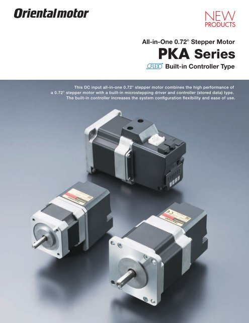
All-in-One 0.72° Stepper <strong>Motor</strong><br />
<strong>PKA</strong> <strong>Series</strong><br />
Built-in Controller Type<br />
This DC input all-in-one 0.72° stepper motor combines the high performance of<br />
a 0.72° stepper motor with a built-in microstepping driver and controller (stored data) type.<br />
The built-in controller increases the system configuration flexibility and ease of use.
This all-in-one 0.72° stepper motor features a built-in<br />
controller (stored data) type, microstepping driver and<br />
high performance motor integrated into one compact<br />
package.<br />
There is no wiring needed between the controller,<br />
driver and motor, providing easy motion control of the<br />
high performance 0.72° stepper motor.<br />
There are three control methods that can be selected,<br />
I/O, Modbus (RTU)/RS-485 or Factory Automation (FA)<br />
Network.<br />
All-in-One Simplifies Motion Control<br />
Built-in Controller (Stored Data) Type<br />
The controller and driver are integrated onto the 0.72º high<br />
performance stepper motor. Since there is a built-in controller<br />
there is no need for a pulse generator. The system is simplified and<br />
requires less wiring.<br />
<strong>Motor</strong><br />
Driver and Controller<br />
Control Module<br />
OPX-2A<br />
(Sold separately)<br />
Data Setting Software ✽1<br />
MEXE02<br />
or<br />
Computer<br />
(Not supplied)<br />
Advantages of the All-in-One High Performance 0.72° Stepper <strong>Motor</strong><br />
By combining the high performance motor with a built-in<br />
microstepping driver and stored data controller, superior noise and<br />
vibration reduction can be easily achieved.<br />
Vibration Component Voltage Vp-p [V]<br />
2.0<br />
1.6<br />
1.2<br />
0.8<br />
0.4<br />
Comparison of Vibration Characteristics<br />
CSK566-NATA 0.72˚/step<br />
<strong>PKA</strong>566KD 0.72˚/step<br />
0 0 100 200 300 400<br />
Speed [r/min]<br />
<strong>Motor</strong><br />
✽1 Data Setting Software MEXE02<br />
Operating data settings, parameter<br />
changes and monitoring are done on a<br />
computer.<br />
Compatible software can be downloaded from the<br />
<strong>Oriental</strong> <strong>Motor</strong> website.<br />
www.orientalmotor.com<br />
RS-485<br />
Communication<br />
RS-485<br />
Communication<br />
●Operating Status Waveform Monitoring<br />
2
All-in-One 0.72º Stepper <strong>Motor</strong><br />
● When Controlling with I/O ● When Controlling with<br />
Serial Communication<br />
Power<br />
Supply<br />
Module<br />
CPU<br />
Module<br />
I/O<br />
Module<br />
Power<br />
Supply<br />
Module<br />
CPU<br />
Module<br />
Serial<br />
Communication<br />
Module<br />
● When Controlling from a<br />
Touch Screen or Computer<br />
Touch Screen or Computer<br />
● When Controlling with<br />
Factory Automation (FA) Network<br />
Power<br />
Supply<br />
Module<br />
CPU<br />
Module<br />
FA Network<br />
Module<br />
3 FA Network<br />
CC-Link<br />
MECHATROLINK-<br />
MECHATROLINK-<br />
EtherCAT<br />
1 I/O 2 Modbus (RTU) 2 Modbus (RTU)<br />
Network<br />
Converter<br />
2 RS-485<br />
Reduces the Burden on the Master Controller<br />
I/O<br />
Programmable Controller<br />
Modbus (RTU)/RS-485<br />
Computer<br />
or<br />
Programmable Controller<br />
Factory Automation (FA) Network<br />
The positioning module (pulse generator)<br />
function is built-in to the driver, allowing the<br />
operation to use I/O by directly connecting<br />
to a switch box or PLC. Because a<br />
positioning module is not necessary on the<br />
PLC side, space is saved and the system is<br />
simplified.<br />
Operating data and parameters can be set<br />
and operation commands can be input using<br />
RS-485 communication. Up to 31 drivers can<br />
be connected to each serial communication<br />
module. Also, there is a function that enables<br />
the simultaneous start of multiple axes. The<br />
protocol supports Modbus (RTU), enabling<br />
connection with devices such as touch<br />
screen (HMI) and PCs.<br />
Use of a network converter (sold separately) ✽2 enables support<br />
with CC-Link, MECHATROLINK or EtherCAT communication.<br />
Operating data and parameters can be set and operation<br />
commands can be input using various communication methods.<br />
CC-Link<br />
MECHATROLINK<br />
EtherCAT<br />
Communication<br />
Network Converter Programmable Controller<br />
NETC01-CC (Sold separately)<br />
NETC01-M2 (Sold separately)<br />
NETC01-M3 (Sold separately)<br />
NETC01-ECT (Sold separately)<br />
✽2 A network converter converts<br />
various network protocols to the<br />
RS-485 communication protocol<br />
used in <strong>Oriental</strong> <strong>Motor</strong> products.<br />
A positioning function is built-in, ensuring that the traveling amount, speed and<br />
other operating data is retained in the motor. It is also equipped with a variety<br />
of other operation functions in addition to the positioning operation, such as<br />
continuous operation and a return-to-home operation. This contributes to a<br />
reduced load on the programmable controller and a simplified program.<br />
●Positioning Operation<br />
The motor's operating speed and traveling amount are set in the operating data<br />
and operations are performed in accordance with the selected operating data.<br />
◇Linked Operation<br />
If the operating data is set to "linked", continuous positioning with<br />
the following data number is possible with one START signal.<br />
[Linked operation]<br />
Data<br />
No. 01<br />
Data<br />
No. 01<br />
Data<br />
No. 02<br />
[Linked operation 2]<br />
CW rotation Dwell time<br />
CCW rotation<br />
Data<br />
No. 02<br />
Data<br />
No. 03<br />
Data<br />
No. 03<br />
If data No. 01 is selected and the START input,<br />
linked driving from data No. 01 to No. 03 is<br />
performed without the motor stopping.<br />
If data No. 01 is selected and the START input,<br />
the data No. 01 operation is executed. After<br />
that, it is stopped for only the set dwell time ✽<br />
and then the operations from data No. 02 to<br />
No. 03 are executed. Operating data with a<br />
different rotation direction can also be linked.<br />
✽ Dwell time is the wait time until the next<br />
positioning operation starts.<br />
◇Sequential Operation<br />
If the operating data is set to "sequential positioning", positioning of the next<br />
data number is performed in sequence every time a SSTART signal is input.<br />
●Speed Control Operation<br />
The motor operates continuously while a FWD signal or RVS signal is input.<br />
Because it operates at the speed of the operating data set beforehand,<br />
multistep speed-change operation is possible by changing the data number.<br />
+Direction<br />
<strong>Motor</strong> operation<br />
−Direction<br />
FWD input<br />
RVS input<br />
M0∼M5 input<br />
ON<br />
OFF<br />
ON<br />
OFF<br />
ON<br />
OFF<br />
01 02 01 03<br />
●Return-To-Home Operation<br />
Equipped with a sequence for return-to-home operation that<br />
reduces the burden of the host (master controller) and the hassle of<br />
combining programs or sequences. A separate sensor is required.<br />
3
■System Configuration<br />
Accessories (Sold separately)<br />
1Control Module Cable ✽2<br />
(➜ Page 10)<br />
2Control Module ✽2<br />
(➜ Page 10)<br />
3Data Setting Software<br />
Communication Cable ✽2<br />
(➜ Page 10)<br />
Data Setting Software<br />
MEXE02 ✽3<br />
or<br />
To USB port<br />
Computer ✽1<br />
<strong>PKA</strong> <strong>Series</strong><br />
24 VDC Power<br />
Supply ✽1<br />
Programmable<br />
Controller ✽1<br />
Sensor ✽1<br />
Accessories (Sold separately)<br />
Related <strong>Product</strong>s (Sold separately)<br />
4 <strong>Motor</strong> Mounting<br />
Bracket ✽4<br />
5Flexible Coupling ✽4<br />
6 RS-485 Communication Cable<br />
(➜ Page 11)<br />
Network Converter<br />
(➜ Page 12)<br />
Number Name Overview Page<br />
1 Control Module Cable This is a cable that connects a control module or data setting software communication cable to the <strong>PKA</strong> <strong>Series</strong>. [0.1 m (0.33 ft.)] 10<br />
2 Control Module Various data can be edited, monitored and operated. Communication cable [5 m (16.4 ft.)] included. 10<br />
3<br />
Data Setting Software<br />
Communication Cable<br />
This communication cable is required for connecting to the computer on which the data setting software is installed. 10<br />
4 <strong>Motor</strong> Mounting Bracket This is a dedicated mounting bracket for the motor. ✽4<br />
5 Flexible Coupling This is a coupling that connects the motor shaft to the driven shaft. ✽4<br />
6<br />
7<br />
RS-485 Communication<br />
Cable<br />
Network Converter<br />
This cable is used for daisy-chain connection of the <strong>PKA</strong> <strong>Series</strong>.<br />
There are cables for connecting the <strong>PKA</strong> <strong>Series</strong> and a network converter, or the <strong>PKA</strong> <strong>Series</strong> and other RS-485 compatible products.<br />
This converts from the host communication protocols to <strong>Oriental</strong> <strong>Motor</strong>'s own RS-485 communication protocol.<br />
The <strong>PKA</strong> series can be controlled using CC-Link, MECHATROLINK or via EtherCAT communications.<br />
●A User's Manual that explains how to operate this product is available. For details, please contact the nearest <strong>Oriental</strong> <strong>Motor</strong> sales office or download the manual from the<br />
<strong>Oriental</strong> <strong>Motor</strong> website. www.orientalmotor.com<br />
11<br />
12<br />
●Example of System Configuration<br />
<strong>PKA</strong> <strong>Series</strong><br />
<strong>PKA</strong>566KD<br />
<strong>Motor</strong><br />
Mounting Bracket<br />
PAL2P-5<br />
Sold Separately<br />
Flexible<br />
Coupling<br />
MCS200808<br />
✽1<br />
Not supplied.<br />
✽2<br />
This is required for driving I/O control.<br />
✽3<br />
Compatible software can be downloaded from the <strong>Oriental</strong> <strong>Motor</strong> website.<br />
✽4 For details, please contact the nearest <strong>Oriental</strong> <strong>Motor</strong> sales office.<br />
● The system confi guration shown above is an example. Other combinations are also available.<br />
■<strong>Product</strong> Line<br />
<strong>Product</strong> Name List Price<br />
<strong>PKA</strong>544KD $415.00<br />
<strong>PKA</strong>566KD $432.00<br />
4
■ Specifications<br />
<strong>Product</strong> Name <strong>PKA</strong>544KD <strong>PKA</strong>566KD<br />
Maximum Holding Torque N·m (oz-in) 0.18 (25) 0.83 (117)<br />
Holding Torque at <strong>Motor</strong> Standstill Power ON N·m (oz-in) 0.09 (12.7) 0.41 (58)<br />
Rotor Inertia J:kg·m 2 (oz-in 2 ) 54×10 -7 (0.3) 280×10 -7 (1.53)<br />
Rated Current A/Phase 0.75 1.4<br />
Basic Step Angle 0.72˚<br />
Power Source 24 VDC±10% 1.4 A 24 VDC±10% 2.5 A<br />
Excitation Mode<br />
Microstep<br />
■Speed – Torque Characteristics<br />
<strong>PKA</strong>544KD<br />
Current [A]<br />
2<br />
1<br />
0<br />
Torque [oz-in]<br />
25<br />
20<br />
15<br />
10<br />
5<br />
0<br />
Torque [N·m]<br />
Current: 0.75 A/Phase Step Angle: 0.72˚/step<br />
External Load Inertia: JL=0 kg·m 2 (0 oz-in 2 )<br />
0.20<br />
0.15<br />
0.10<br />
0.05<br />
fs<br />
0<br />
0 500 1000 1500 2000 2500<br />
Speed [r/min]<br />
0<br />
(0)<br />
5<br />
(50)<br />
Driver Input Current<br />
10<br />
(100)<br />
Pullout Torque<br />
Pulse Speed [kHz]<br />
15<br />
(150)<br />
Resolution: 500<br />
(Resolution: 5000)<br />
<strong>PKA</strong>566KD<br />
Current [A]<br />
4<br />
2<br />
0<br />
Torque [oz-in]<br />
160<br />
120<br />
80<br />
40<br />
0<br />
Torque [N·m]<br />
Current: 1.4 A/Phase Step Angle: 0.72˚/step<br />
External Load Inertia: JL=0 kg·m 2 (0 oz-in 2 )<br />
1.2<br />
1.0<br />
0.8<br />
0.6<br />
0.4<br />
0.2<br />
fs<br />
0<br />
0 200 400 600 800 1000 1200<br />
Speed [r/min]<br />
0<br />
(0)<br />
Pullout Torque<br />
Driver Input Current<br />
2.5<br />
(25)<br />
5<br />
(50)<br />
Pulse Speed [kHz]<br />
7.5<br />
(75)<br />
Resolution: 500<br />
(Resolution: 5000)<br />
Note<br />
●Depending on the driving conditions, a considerable amount of heat may be generated by the motor. Be sure to keep the motor case temperature at 75˚C (167˚F) max.<br />
■Control Circuit Specifications<br />
No. of Positioning Data Sets 64<br />
Operation Functions<br />
Positioning operation, return-to-home operation, continuous operation, JOG operation, test operation<br />
■Control Circuit RS-485 Communication Specification<br />
Protocol<br />
Modbus protocol (Modbus RTU mode)<br />
Electrical Characteristics<br />
EIA-485 compliance<br />
Twisted-pair wire (TIA/EIA-568B CAT5e or greater recommended) is used up to a total extension length of 50 m (164 ft.).<br />
Sending and Receiving Method Half-duplex communication<br />
Baud Rate<br />
9600 bps/19200 bps/38400 bps/57600 bps/115200 bps<br />
Physical Layer<br />
Start-stop synchronization method (data: 8-bit, stop bit: 1-bit/2-bit, parity: none/odd/even)<br />
Connection Type<br />
Up to 31 units can be connected to one programmable controller (master controller).<br />
■General Specifications<br />
Specifications<br />
<strong>Motor</strong><br />
Heat-Resistant Class<br />
130 (B)<br />
The measured value is 100 MΩ min. when a 500 VDC megger is applied as follows under normal ambient temperature<br />
Insulation Resistance<br />
and humidity:<br />
• FG terminal and motor case − Between power input terminals<br />
No abnormality is found with the following application for 1 minute under normal ambient temperature and humidity:<br />
Dielectric Strength<br />
• FG terminal and motor case − Between power input terminals 500 VAC 50 Hz or 60 Hz<br />
Ambient<br />
Operating<br />
0∼50˚C (+32∼+122˚F) (non-freezing)<br />
Temperature<br />
Environment<br />
Ambient Humidity<br />
85% max. (non-condensing)<br />
(In operation)<br />
Atmosphere Use in an area without corrosive gases and dust. The product should not be exposed to water, oil or other liquids.<br />
Degree of Protection<br />
IP20<br />
Temperature rise of the windings are 80˚C (176˚F) max. (measured by the resistance change method)<br />
Temperature Rise<br />
at the rated current, at standstill, and 5-phases energized.<br />
Stop Position Accuracy ✽1<br />
±3 arc minutes (±0.05˚)<br />
Shaft Runout<br />
0.05 mm (0.002 in.) T.I.R. ✽4<br />
Radial Play ✽2<br />
0.025 mm (0.001 in.) Maximum of 5 N (1.12 lb.)<br />
Axial Play ✽3<br />
0.075 mm (0.003 in.) Maximum of 10 N (2.2 lb.)<br />
Concentricity of Installing Pilot to<br />
0.075 mm (0.003 in.) T.I.R. ✽4<br />
the Shaft<br />
Perpendicularity of Installation<br />
0.075 mm (0.003 in.) T.I.R. ✽4<br />
Surface to the Shaft<br />
✽1 This value is for full step under no load. (The value changes with the size of the load.)<br />
✽2 Radial Play: Displacement in shaft position in the radial direction, when a 5 N (1.12 lb.) load is applied in the vertical direction to the tip of the motor's<br />
shaft.<br />
✽3 Axial Play: Displacement in shaft position in the axial direction, when a 10 N (2.2 lb.) load is applied to the motor shaft in the axial direction.<br />
✽4 T. I. R. (Total Indicator Reading): The total dial gauge reading when the measurement section is rotated one revolution centered on the reference axis<br />
center.<br />
ϕ0.075<br />
0.05<br />
A<br />
0.075 A<br />
A<br />
5
■Permissible Overhung Load and Permissible Thrust Load<br />
Max. Permissible Overhung Load<br />
<strong>Motor</strong><br />
<strong>Product</strong> Name<br />
Distance from Shaft End mm [in.]<br />
Frame Size<br />
0 [0] 5 [0.2] 10 [0.39] 15 [0.59] 20 [0.79]<br />
42 mm [1.65 in.] <strong>PKA</strong>544KD 20 (4.5) 25 (5.6) 34 (7.6) 52 (11.7) −<br />
60 mm [2.36 in.] <strong>PKA</strong>566KD 63 (14.1) 75 (16.8) 95 (21) 130 (29) 190 (42)<br />
Unit N (lb.)<br />
Permissible Thrust<br />
Load<br />
<strong>Motor</strong> Self-Weight max.<br />
■Dimensions<br />
Unit mm (in.)<br />
●<strong>Motor</strong><br />
Frame Size 42 mm (1.65 in.)<br />
<strong>Product</strong> Name Mass kg (lb.) CAD<br />
<strong>PKA</strong>544KD 0.37 (0.81) B798<br />
88.5 (3.48) 20±1 (0.79±0.04)<br />
39 2 (0.08)<br />
(1.54) 15±0.25<br />
(0.591±0.010)<br />
4×M3×4.5 (0.18) Deep<br />
42 (1.65)<br />
31±0.2<br />
(1.220±0.008)<br />
55959−1230 (Molex)<br />
43045−0400 (Molex)<br />
11.7<br />
(0.46)<br />
62.8<br />
(2.47)<br />
4.5±0.15<br />
(0.177±0.006)<br />
0<br />
ϕ5−0.012<br />
0 (ϕ0.1969−0.005)<br />
0<br />
ϕ22−0.033<br />
0 (ϕ0.8661−0.0013)<br />
15.4<br />
(0.61) 30.5<br />
(1.20)<br />
31±0.2<br />
(1.220±0.008)<br />
42 (1.65)<br />
56±1<br />
(2.20±0.04)<br />
60<br />
(2.36)<br />
Frame Size 60 mm (2.36 in.)<br />
<strong>Product</strong> Name Mass kg (lb.) CAD<br />
<strong>PKA</strong>566KD 0.89 (1.96) B799<br />
42(1.65)<br />
107 (4.21)<br />
57.5 (2.26)<br />
24±1 (0.94±0.04)<br />
1.5 (0.06)<br />
20±0.25<br />
(0.787±0.010)<br />
4×ϕ4.5 (ϕ0.177) Thru<br />
60 (2.36)<br />
50±0.35<br />
(1.969±0.014)<br />
15.4<br />
(0.61)<br />
60 (2.36)<br />
56 (2.20)<br />
11.7<br />
(0.46)<br />
32<br />
(1.26)<br />
A<br />
A<br />
0<br />
ϕ8−0.015<br />
0<br />
(ϕ0.3150±0.006)<br />
0<br />
ϕ36−0.039<br />
0<br />
(ϕ1.4173±0.0015)<br />
30<br />
(1.18)<br />
50±0.35<br />
(1.969±0.014)<br />
60<br />
(2.36)<br />
10<br />
(0.39)<br />
55959−1230 (Molex)<br />
43045−0400 (Molex)<br />
90°<br />
7.5±0.15<br />
(0.295±0.006)<br />
7.5±0.15<br />
(0.295±0.006)<br />
A−A<br />
●Connection Cable (Included)<br />
1 2<br />
9.3<br />
(0.37)<br />
600±20<br />
(23.62±0.79)<br />
15.4<br />
(0.61)<br />
11 12<br />
6
■Connection and Operation<br />
●Names and Function of Parts<br />
Power Supply & I/O Signal<br />
Connector (CN1)<br />
RS-485 Communication Connector<br />
(CN2, 3)<br />
Control Module Connector (CN4)<br />
Baud Rate Setting Switch<br />
(SW3)<br />
Axis Setting Switch<br />
(SW2)<br />
Signal Monitor Display<br />
Function Switch (SW1)<br />
Signal Monitor Display<br />
◇LED Indicator<br />
Indication Color Function Lighting Condition<br />
PWR Green Power Supply Indication When the power supply is input<br />
ALM Red Alarm Indication When a protective function is activated (blinking)<br />
DAT Green Communication Indication When data is being received or sent<br />
ERR Red Communication Error Indication When a communication error has occured<br />
Function Switch (SW1)<br />
Indication No. Function<br />
SW1<br />
1, 2<br />
Sets the terminating resistor for RS-485 communication (120 Ω) (factory setting: OFF).<br />
OFF: Terminating resistor not used<br />
ON: Terminating resistor used<br />
3 Sets the model number in combination with the model setting switch (SW2) (factory setting: OFF).<br />
4 Sets the protocol for RS-485 communication (factory setting: OFF).<br />
◇Settings for RS-485 Communication Protocol<br />
Destination<br />
Network<br />
Modbus RTU Mode<br />
No.<br />
Converter Connection<br />
4 OFF ON<br />
Axis Setting Switch (SW2)<br />
Indication<br />
Function<br />
SW2 Set when using with RS-485 communication. Set the axis number (factory setting: 0).<br />
Baud Rate Setting Switch (SW3)<br />
Indication<br />
Function<br />
SW3 Set when using with RS-485 communication. Set the baud rate (factory setting: 7).<br />
◇RS-485 Baud Rate Setting<br />
No.<br />
Baud Rate (bps)<br />
0 9600<br />
1 19200<br />
2 38400<br />
3 57600<br />
4 115200<br />
5∼6<br />
Not used<br />
625000<br />
7<br />
Connect with a network converter<br />
8∼F<br />
Not used<br />
7
Power Supply & I/O Signal Connector (CN1)<br />
Indication Pin No. Signal Name Content<br />
1 FG Frame ground<br />
2 GND Power supply GND<br />
3 IN-COM Input common<br />
4 +24 VDC +24 VDC power supply input<br />
5 IN0 Control input 0 (initial value: +LS) ✽<br />
6 IN1 Control input 1 (initial value: −LS) ✽<br />
CN1<br />
7 IN2 Control input 2 (initial value: HOMES) ✽<br />
8 IN3 Control input 3 (initial value: STOP) ✽<br />
9 OUT0+<br />
Control output 0 (initial value: ALM) ✽<br />
10 OUT0−<br />
Control output 1 (initial value: READY) ✽<br />
11 OUT1+<br />
12 OUT1−<br />
✽Sets the function to be assigned according to the parameter setting. The initial values are shown above. For details, refer to the User's Manual.<br />
The following input signals can be assigned to input terminals IN0∼3.<br />
Input Signal<br />
0: Not used 8: MS0 18: STOP 36: R4 44: R12 52: M4<br />
1: FWD 9: MS1 24: ALM-RST 37: R5 45: R13 53: M5<br />
2: RVS 10: MS2 25: P-PRESET 38: R6 46: R14 60: +LS<br />
3: HOME 11: MS3 27: HMI 39: R7 47: R15 61: −LS<br />
4: START 12: MS4 32: R0 40: R8 48: M0 62: HOMES<br />
5: SSTART 13: MS5 33: R1 41: R9 49: M1 63: SLIT<br />
6: +JOG 16: FREE 34: R2 42: R10 50: M2<br />
7: −JOG 17: AWO 35: R3 43: R11 51: M3<br />
The following output signals can be assigned to output terminal OUT0∼1.<br />
Output Signal<br />
0: Not used 9: MS1_R 33: R1 42: R10 51: M3_R 67: READY<br />
1: FWD_R 10: MS2_R 34: R2 43: R11 52: M4_R 68: MOVE<br />
2: RVS_R 11: MS3_R 35: R3 44: R12 53: M5_R 70: HOME-P<br />
3: HOME_R 12: MS4_R 36: R4 45: R13 60: +LS_R 72: TIM<br />
4: START_R 13: MS5_R 37: R5 46: R14 61: −LS_R 73: AREA1<br />
5: SSTART_R 16: FREE_R 38: R6 47: R15 62: HOMES_R 74: AREA2<br />
6: +JOG_R 17: AWO_R 39: R7 48: M0_R 63: SLIT_R 75: AREA3<br />
7: −JOG_R 18: STOP_R 40: R8 49: M1_R 65: ALM 80: S-BSY<br />
8: MS0_R 32: R0 41: R9 50: M2_R 66: WNG<br />
8
●Connection Diagram<br />
◇Connection to Programmable Controller<br />
● Example of Connection with Current Sink Output Circuit (NPN specification)<br />
Controller<br />
Control Circuit<br />
IN0<br />
6.6 kΩ<br />
IN1<br />
6.6 kΩ<br />
1 kΩ<br />
IN2<br />
6.6 kΩ<br />
1 kΩ<br />
IN3<br />
6.6 kΩ<br />
1 kΩ<br />
0 V<br />
+24 VDC<br />
IN-COM<br />
1 kΩ<br />
+24 VDC max.<br />
0 V<br />
R<br />
R<br />
10 mA max.<br />
OUT0+<br />
OUT0−<br />
OUT1+<br />
OUT1−<br />
● Example of Connection with Current Source Output Circuit (PNP specification)<br />
Controller<br />
Control Circuit<br />
+24 VDC<br />
IN0<br />
IN1<br />
IN2<br />
IN3<br />
IN-COM<br />
6.6 kΩ<br />
6.6 kΩ<br />
6.6 kΩ<br />
6.6 kΩ<br />
1 kΩ<br />
1 kΩ<br />
1 kΩ<br />
1 kΩ<br />
+24 VDC max.<br />
0 V<br />
10 mA max.<br />
OUT0+<br />
R<br />
OUT0−<br />
OUT1+<br />
R<br />
OUT1−<br />
0 V<br />
Notes<br />
●Use 24 VDC for the input signals.<br />
●Use 24 VDC 10 mA max. for the output signals. When the current value exceeds 10 mA, connect the external resistor R to keep the current 10 mA max.<br />
●If noise generated by the power supply cable causes a problem with the specific wiring or layout, shield the cable or use ferrite cores.<br />
9
Accessories (Sold separately)<br />
These accessories are necessary to change operating data such as parameter settings and data settings in the<br />
<strong>PKA</strong> <strong>Series</strong>.<br />
Control Module Cable<br />
CC001IF-CA<br />
CN4<br />
Control Module<br />
OPX-2A<br />
Control Module Cable<br />
This is a cable that connects an OPX-2A or data setting software<br />
communication cable to the <strong>PKA</strong> <strong>Series</strong>.<br />
or<br />
Data Setting Software<br />
MEXE02<br />
Computer<br />
(Not supplied.)<br />
Connected to Control Module Cable<br />
USB Cable<br />
0.5 m (20 in.)<br />
Communication Cable for Data<br />
Setting Software<br />
CC05IF-USB<br />
PC Interface Cable 5 m (16.4 ft.)<br />
Note<br />
●A dedicated driver must be installed to connect to a computer.<br />
■<strong>Product</strong> Line<br />
<strong>Product</strong> Name List Price<br />
CC001IF-CA $9.00<br />
■Dimensions<br />
6.8<br />
(0.27)<br />
unit mm (in.)<br />
ϕ9.9<br />
(ϕ0.39)<br />
ϕ13<br />
(ϕ0.5)<br />
Control Module<br />
Perform operations such as setting the driver's internal parameters and<br />
setting or changing the data. It can also be used for operations such as<br />
speed and I/O monitoring and teaching.<br />
10.4<br />
(0.41)<br />
6.85<br />
(0.27)<br />
ϕ2.8 (ϕ0.11)<br />
5.5 28.6 100±10<br />
(0.22) (1.13) (3.94±0.39)<br />
36 2<br />
(1.41) (0.08)<br />
■<strong>Product</strong> Line<br />
<strong>Product</strong> Name List Price<br />
OPX-2A $300.00<br />
■Dimensions<br />
<br />
Unit mm (in.)<br />
■Specifications<br />
Indication<br />
Cable Length<br />
Operating Ambient Temperature<br />
LED<br />
5 m (16.4 ft.)<br />
0∼40˚C (+32∼+104˚F) (non-freezing)<br />
●Control Module<br />
Mass: 0.25 kg (0.55 lb.)<br />
B453<br />
91.8 (3.61)<br />
●Panel Cut-Out for<br />
Controller Module<br />
[Installation Plate Thickness 1∼3 mm<br />
(0.04∼0.12 in.)]<br />
96 (3.78)<br />
6.1<br />
(0.28)<br />
21.5<br />
(0.85)<br />
+0.7<br />
68 0<br />
(2.677 +0.028<br />
0 )<br />
72 (2.83)<br />
67.8 (2.67)<br />
92 +0.8 0 ( 3.622 +0.031<br />
0 )<br />
Cable ϕ4.7 (ϕ0.19), 5000 (196.9)<br />
38 (1.50)<br />
ϕ11.2<br />
(0.44)<br />
Data Setting Software Communication Cable<br />
This communication cable is required for connecting to the computer on which the data setting software is installed.<br />
■<strong>Product</strong> Line<br />
<strong>Product</strong> Name List Price<br />
CC05IF-USB $120.00<br />
10
■Data Setting Software<br />
MEXE02<br />
The data setting software can be downloaded from the <strong>Oriental</strong> <strong>Motor</strong> website. www.orientalmotor.com<br />
For details, please go to the <strong>Oriental</strong> <strong>Motor</strong> website or contact the nearest <strong>Oriental</strong> <strong>Motor</strong> sales office.<br />
■Operating Environment<br />
●Operating System (OS)<br />
●Microsoft Windows 2000 Professional Service Pack 4<br />
Be sure to install Rollup 1 provided by Microsoft Corporation.<br />
Check whether Rollup 1 has been installed in "Add or Remove<br />
Programs".<br />
For the following operating systems, both the 32-bit (x86) edition<br />
and 64-bit (x64) edition are supported.<br />
●Microsoft Windows XP Home Edition Service Pack 3<br />
●Microsoft Windows XP Professional Service Pack 2<br />
✽1<br />
●Microsoft Windows XP Professional Service Pack 3<br />
●Microsoft Windows Vista Home Basic Service Pack 2<br />
●Microsoft Windows Vista Home Premium Service Pack 2<br />
●Microsoft Windows Vista Business Service Pack 2<br />
●Microsoft Windows Vista Ultimate Service Pack 2<br />
●Microsoft Windows Vista Enterprise Service Pack 2<br />
●Microsoft Windows 7 Starter Service Pack 1<br />
●Microsoft Windows 7 Home Premium Service Pack 1<br />
●Microsoft Windows 7 Professional Service Pack 1<br />
●Microsoft Windows 7 Ultimate Service Pack 1<br />
●Microsoft Windows 7 Enterprise Service Pack 1<br />
✽1 32-bit (x86) version only<br />
●PC<br />
Intel Core processor 2 GHz min.<br />
Recommended CPU ✽2<br />
(Must be compatible with OS)<br />
Video adapter and monitor with resolution of XGA (1024 ×<br />
Display<br />
768) min.<br />
32-bit version (x86): 1 GB min.<br />
Recommended Memory ✽2<br />
64-bit version (x64): 2 GB min.<br />
Hard Disk ✽3<br />
Free disk space of 30 MB min.<br />
USB Port<br />
USB 1.1 1 Port<br />
Disk Device<br />
CD-ROM Drive (Used for installation)<br />
✽2 The operating conditions of the OS must be satisfied.<br />
✽3 Microsoft .NET Framework 2.0 Service Pack 2 is required for MEXE02. If it is not<br />
installed, it will be installed automatically. An additional max. of 500 MB of free space may<br />
be required.<br />
Notes<br />
●The required memory and hard disk space may vary depending on the system environment.<br />
●Windows and Windows Vista are registered trademarks of the Microsoft Corporation in the<br />
United States and other countries.<br />
RS-485 Communication Cable<br />
This is an RS-485 communication cable.<br />
CC020-RS4A<br />
CC020-RS4B<br />
■<strong>Product</strong> Line<br />
<strong>Product</strong> Name Overview Length m (ft.) List Price<br />
CC020-RS4A This cable is used for daisy-chain connection of the <strong>PKA</strong> <strong>Series</strong>. 2 (6.6) $35.00<br />
CC020-RS4B<br />
There are cables for connecting the <strong>PKA</strong> <strong>Series</strong> and a network converter, or the <strong>PKA</strong><br />
<strong>Series</strong> and other RS-485 compatible products.<br />
2 (6.6) $50.00<br />
■Dimensions<br />
CC020-RS4A<br />
unit mm (in.)<br />
●Connection Example<br />
CC020-RS4B<br />
Network Converter<br />
CC020-RS4A<br />
43025-0400 (Molex)<br />
43025-0400 (Molex)<br />
7.57 (0.30)<br />
10.85 (0.43)<br />
CN3<br />
CN2<br />
ϕ6.2<br />
(ϕ0.24)<br />
2000 +80 0<br />
( 78.74<br />
+3.15<br />
0 )<br />
14<br />
(0.55)<br />
8.26<br />
(0.33)<br />
CC020-RS4B<br />
MP588 (Panduit)<br />
43025-0400 (Molex)<br />
13<br />
(0.51)<br />
7.57<br />
(0.30)<br />
10.85<br />
(0.43)<br />
11.7<br />
(0.46)<br />
22.9<br />
(0.90)<br />
ϕ6.2 (ϕ0.24)<br />
2000 +80 0<br />
+3.15<br />
( 78.74 0 )<br />
14<br />
(0.55)<br />
8.26<br />
(0.33)<br />
11
Related <strong>Product</strong>s (Sold separately)<br />
Network Converter<br />
A network converter converts from the host<br />
communication protocols to <strong>Oriental</strong> <strong>Motor</strong>'s own<br />
RS-485 communication protocol. Use the network<br />
converter to control products supporting <strong>Oriental</strong><br />
<strong>Motor</strong>'s RS-485 compatible products in the host<br />
communication environment.<br />
■Features<br />
●Reduced Wiring and Space Saving is Possible<br />
Only the one included cable is needed for the wiring when<br />
connecting to an RS-485-compatible product.<br />
●Setting Method for Various Parameters<br />
A control module OPX-2A (sold separately) or data setting<br />
software MEXE02 is required for setting a network converter.<br />
A control module OPX-2A and data setting software MEXE02 can<br />
also be used to monitor the time it takes to communicate with each<br />
axis.<br />
●Multi-axis Connection is Possible<br />
RS-485-compatible products can be connected on multiple axes.<br />
●CC-Link-compatible: 12 axes max.<br />
●MECHATROLINK-<br />
-compatible: 16 axes max.<br />
●MECHATROLINK-<br />
-compatible: 16 axes max.<br />
●EtherCAT-compatible: 16 axes max.<br />
NETC01-CC NETC01-M2 NETC01-M3 NETC01-ECT<br />
■<strong>Product</strong> Line<br />
Network <strong>Product</strong> Line <strong>Product</strong> Name List Price<br />
CC-Link-compatible NETC01-CC $282.00<br />
MECHATROLINK- -compatible NETC01-M2 $358.00<br />
EtherCAT-compatible NETC01-ECT $510.00<br />
The following items are included in each product.<br />
Network converter, RS-485 communication cable, power supply connector, operating<br />
manual, CC-Link communication connector (NETC01-CC only)<br />
ORIENTAL MOTOR U.S.A. CORP.<br />
Western Sales and<br />
Customer Service Center<br />
Tel: (310) 715-3301 Fax: (310) 225-2594<br />
Los Angeles<br />
Tel: (310) 715-3301<br />
San Jose<br />
Tel: (408) 392-9735<br />
Technical Support<br />
Tel: (800) 468-3982 / 8:30 A.M. to 5:00 P.M., P.S.T. (M–F)<br />
7:30 A.M. to 5:00 P.M., C.S.T. (M–F)<br />
E-mail: techsupport@orientalmotor.com<br />
Midwest Sales and<br />
Customer Service Center<br />
Tel: (847) 871-5900 Fax: (847) 472-2623<br />
Chicago<br />
Tel: (847) 871-5900<br />
Dallas<br />
Tel: (214) 432-3386<br />
Toronto<br />
Tel: (905) 502-5333<br />
Specifications are subject to change without notice. This catalog was published in May, 2013.<br />
Obtain Specifications, Online Training<br />
and Purchase <strong>Product</strong>s at:<br />
www.orientalmotor.com<br />
Eastern Sales and<br />
Customer Service Center<br />
Tel: (781) 848-2426 Fax: (781) 848-2617<br />
Boston<br />
Tel: (781) 848-2426<br />
Charlotte<br />
Tel: (704) 766-1335<br />
New York<br />
Tel: (973) 359-1100<br />
Copyright ©2013 ORIENTAL MOTOR U.S.A. CORP.<br />
Printed in USA 13S #419


