

å æ± èª¬ æ æ¸ CRK ã·ãªã¼ãº - Oriental Motor
å æ± èª¬ æ æ¸ CRK ã·ãªã¼ãº - Oriental Motor
å æ± èª¬ æ æ¸ CRK ã·ãªã¼ãº - Oriental Motor

You also want an ePaper? Increase the reach of your titles
YUMPU automatically turns print PDFs into web optimized ePapers that Google loves.
取 扱 説 明 書<br />
HM-40089-8<br />
5 相 ステッピングモーターユニット<br />
<strong>CRK</strong> シリーズ<br />
コントローラ 内 蔵 タイプ(RS-485 通 信 機 能 付 )<br />
お 買 い 上 げいただきありがとうございます。<br />
この 取 扱 説 明 書 には、 製 品 の 取 り 扱 いかたや 安 全 上 の 注 意 事 項 を 示 しています。<br />
• 取 扱 説 明 書 をよくお 読 みになり、 製 品 を 安 全 にお 使 いください。<br />
• お 読 みになったあとは、いつでも 見 られるところに 必 ず 保 管 してください。<br />
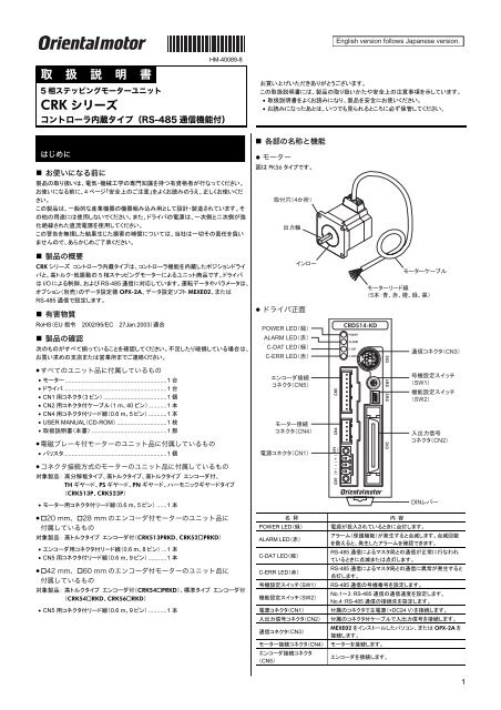
• 各 部 の 名 称 と 機 能<br />
はじめに<br />
• お 使 いになる 前 に<br />
製 品 の 取 り 扱 いは、 電 気 ・ 機 械 工 学 の 専 門 知 識 を 持 つ 有 資 格 者 が 行 なってください。<br />
お 使 いになる 前 に、4 ページ「 安 全 上 のご 注 意 」をよくお 読 みのうえ、 正 しくお 使 いくだ<br />
さい。<br />
この 製 品 は、 一 般 的 な 産 業 機 器 の 機 器 組 み 込 み 用 として 設 計 ・ 製 造 されています。そ<br />
の 他 の 用 途 には 使 用 しないでください。また、ドライバの 電 源 は、 一 次 側 と 二 次 側 が 強<br />
化 絶 縁 された 直 流 電 源 を 使 用 してください。<br />
この 警 告 を 無 視 した 結 果 生 じた 損 害 の 補 償 については、 当 社 は 一 切 その 責 任 を 負 い<br />
ませんので、あらかじめご 了 承 ください。<br />
• 製 品 の 概 要<br />
<strong>CRK</strong> シリーズ コントローラ 内 蔵 タイプは、コントローラ 機 能 を 内 蔵 したポジションドライ<br />
バと、 高 トルク・ 低 振 動 の 5 相 ステッピングモーターによるユニット 商 品 です。ドライバ<br />
は I/O による 制 御 、および RS-485 通 信 に 対 応 しています。 運 転 データやパラメータは、<br />
オプション( 別 売 )のデータ 設 定 器 OPX-2A、データ 設 定 ソフト MEXE02、または<br />
RS-485 通 信 で 設 定 します。<br />
• 有 害 物 質<br />
RoHS(EU 指 令 2002/95/EC 27Jan.2003) 適 合<br />
• 製 品 の 確 認<br />
次 のものがすべて 揃 っていることを 確 認 してください。 不 足 したり 破 損 している 場 合 は、<br />
お 買 い 求 めの 支 店 または 営 業 所 までご 連 絡 ください。<br />
• すべてのユニット 品 に 付 属 しているもの<br />
• モーター .............................................................1 台<br />
• ドライバ..............................................................1 台<br />
• CN1 用 コネクタ(3 ピン) ......................................1 個<br />
• CN2 用 コネクタ 付 ケーブル(1 m、40 ピン)...........1 本<br />
• CN4 用 コネクタ 付 リード 線 (0.6 m、5 ピン) ...........1 本<br />
• USER MANUAL(CD-ROM) ..............................1 枚<br />
• 取 扱 説 明 書 ( 本 書 ) .............................................1 部<br />
• 電 磁 ブレーキ 付 モーターのユニット 品 に 付 属 しているもの<br />
• バリスタ..............................................................1 個<br />
• コネクタ 接 続 方 式 のモーターのユニット 品 に 付 属 しているもの<br />
対 象 製 品 : 高 分 解 能 タイプ、 高 トルクタイプ、 高 トルクタイプ エンコーダ 付 、<br />
TH ギヤード、PS ギヤード、PN ギヤード、ハーモニックギヤードタイプ<br />
(<strong>CRK</strong>513P、<strong>CRK</strong>523P)<br />
• モーター 用 コネクタ 付 リード 線 (0.6 m、5 ピン) ......1 本<br />
• 20 mm、28 mm のエンコーダ 付 モーターのユニット 品 に<br />
付 属 しているもの<br />
対 象 製 品 : 高 トルクタイプ エンコーダ 付 (<strong>CRK</strong>513PRKD、<strong>CRK</strong>52PRKD)<br />
• エンコーダ 用 コネクタ 付 リード 線 (0.6 m、8 ピン) ...1 本<br />
• CN5 用 コネクタ 付 リード 線 (0.6 m、9 ピン) ...........1 本<br />
• 42 mm、60 mm のエンコーダ 付 モーターのユニット 品 に<br />
付 属 しているもの<br />
対 象 製 品 : 高 トルクタイプ エンコーダ 付 (<strong>CRK</strong>54PRKD)、 標 準 タイプ エンコーダ 付<br />
(<strong>CRK</strong>54RKD、<strong>CRK</strong>56RKD)<br />
• CN5 用 コネクタ 付 リード 線 (0.6 m、9 ピン) ...........1 本<br />
● モーター<br />
図 は PK56 タイプです。<br />
4<br />
<br />
● ドライバ 正 面<br />
<br />
POWER LED<br />
ALARM LED<br />
C-DAT LED<br />
C-ERR LED<br />
<br />
CN5<br />
<br />
CN4<br />
CN1<br />
名 称<br />
POWER LED( 緑 )<br />
ALARM LED( 赤 )<br />
C-DAT LED( 緑 )<br />
C-ERR LED( 赤 )<br />
号 機 設 定 スイッチ(SW1)<br />
機 能 設 定 スイッチ(SW2)<br />
電 源 コネクタ(CN1)<br />
入 出 力 信 号 コネクタ(CN2)<br />
通 信 コネクタ(CN3)<br />
モーター 接 続 コネクタ(CN4)<br />
エンコーダ 接 続 コネクタ<br />
(CN5)<br />
<br />
<br />
5<br />
内 容<br />
CN3<br />
<br />
SW1<br />
<br />
SW2<br />
<br />
CN2<br />
DIN<br />
電 源 が 投 入 されているときに 点 灯 します。<br />
アラーム( 保 護 機 能 )が 発 生 すると 点 滅 します。 点 滅 回 数<br />
を 数 えると、 発 生 したアラームを 確 認 できます。<br />
RS-485 通 信 によるマスタ 局 との 通 信 が 正 常 に 行 なわれ<br />
ているときに 点 滅 または 点 灯 します。<br />
RS-485 通 信 によるマスタ 局 との 通 信 に 異 常 が 発 生 すると<br />
点 灯 します。<br />
RS-485 通 信 の 号 機 番 号 を 設 定 します。<br />
No.1~3:RS-485 通 信 の 通 信 速 度 を 設 定 します。<br />
No.4:RS-485 通 信 の 接 続 先 を 設 定 します。<br />
付 属 のコネクタで 主 電 源 (+DC24 V)を 接 続 します。<br />
付 属 のコネクタ 付 ケーブルで 入 出 力 信 号 を 接 続 します。<br />
MEXE02 をインストールしたパソコン、または OPX-2A を<br />
接 続 します。<br />
モーターを 接 続 します。<br />
エンコーダを 接 続 します。<br />
1
● ドライバ 上 面<br />
名 称<br />
終 端 抵 抗 設 定 スイッチ(SW3)<br />
RS-485 通 信 コネクタ(CN6/CN7)<br />
設 置<br />
• 設 置 場 所<br />
RS-485<br />
CN6/CN7<br />
SW3<br />
内 容<br />
RS-485 通 信 の 終 端 抵 抗 (120 Ω)を 設 定 します。<br />
RS-485 通 信 ケーブルを 接 続 します。<br />
モーター、ドライバは 機 器 組 み 込 み 用 に 設 計 ・ 製 造 されています。<br />
風 通 しがよく、 点 検 が 容 易 な 次 のような 場 所 に 設 置 してください。<br />
• 屋 内 に 設 置 された 筐 体 内 ( 換 気 口 を 設 けてください)<br />
• 使 用 周 囲 温 度 モーター:-10~+50 °C( 凍 結 しないこと)<br />
ドライバ:0~+40 °C( 凍 結 しないこと)<br />
• 使 用 周 囲 湿 度 85% 以 下 ( 結 露 しないこと)<br />
• 爆 発 性 雰 囲 気 、 有 害 なガス( 硫 化 ガスなど)、および 液 体 のないところ<br />
• 直 射 日 光 が 当 たらないところ<br />
• 塵 埃 や 鉄 粉 などの 少 ないところ<br />
• 水 ( 雨 や 水 滴 )、 油 ( 油 滴 )、およびその 他 の 液 体 がかからないところ<br />
• 塩 分 の 少 ないところ<br />
• 連 続 的 な 振 動 や 過 度 の 衝 撃 が 加 わらないところ<br />
• 電 磁 ノイズ( 溶 接 機 、 動 力 機 器 など)が 少 ないところ<br />
• 放 射 性 物 質 や 磁 場 がなく、 真 空 でないところ<br />
• モーターの 設 置<br />
モーターの 設 置 方 向 に 制 限 はありません。モーターは 耐 振 動 性 にすぐれ、 熱 伝 導 効 果 が<br />
高 い、 平 滑 な 金 属 板 に 設 置 してください。<br />
モーターを 設 置 するときは、4 か 所 の 取 付 穴 を 使 用 して、 金 属 板 との 間 にすき 間 がな<br />
いように、4 本 のボルト( 付 属 していません)で 固 定 してください。<br />
重 要<br />
• A<br />
モーター 取 付 面 にあるインローは、インロー 受 けにはめ 込 んでください。<br />
<br />
• B<br />
<br />
<br />
• ドライバの 設 置<br />
● 設 置 方 向<br />
ドライバは DIN レール(レール 幅 35 mm)に 取 り 付 けてください。また、 筐 体 や 他 の 機<br />
器 から、 水 平 ・ 垂 直 方 向 へ 50 mm 以 上 離 して 設 置 してください。<br />
ドライバを 2 台 以 上 並 べて 設 置 するときのドライバ 間 距 離 は、 次 の 図 をご 覧 ください。<br />
重 要<br />
ドライバは 必 ず 垂 直 ( 縦 位 置 )に 設 置 してください。 垂 直 以 外 の 姿 勢 で 取 り<br />
付 けると、ドライバの 放 熱 効 果 が 低 下 します。<br />
• CRD503-KD、CRD507-KD、CRD507H-KD<br />
水 平 方 向 は 密 着 できます。<br />
垂 直 方 向 は 50 mm 以 上 離 してください。<br />
50 mm<br />
• CRD514-KD<br />
水 平 方 向 は 20 mm 以 上 、 垂 直 方 向 は<br />
50 mm 以 上 離 してください。<br />
20 mm<br />
50 mm<br />
• CRD514-KD とその 他 のドライバを 併 用 するとき<br />
CRD514-KD の 右 側 は 密 着 できます。 左 側 は 放 熱 板 があるため、20 mm 以 上 離 してくだ<br />
さい。<br />
20 mm<br />
● 設 置 方 法<br />
<br />
ドライバの DIN レバーを 引 き 下 げてロックし、 背 面 にあるフックを DIN レールに 掛 けて、<br />
ドライバを 押 し 込 みます。 取 り 付 けた 後 は、エンドプレートでドライバの 両 側 を 固 定 して<br />
ください。<br />
<br />
<br />
<br />
ねじサイズ・ 締 付 トルク・ 設 置 方 法<br />
標 準<br />
高 トルク<br />
高 分 解 能<br />
タイプ<br />
取 付 角<br />
寸 法<br />
(mm)<br />
TH ギヤード 42<br />
60<br />
PS ギヤード<br />
PN ギヤード<br />
ハーモニックギヤード<br />
ボルト<br />
の 呼 び<br />
∗ ハーモニックギヤードの 場 合 は 30 mm です。<br />
<br />
締 付 トルク<br />
(N·m)<br />
有 効 ねじ 深 さ<br />
(mm)<br />
設 置<br />
方 法<br />
20 M2 0.25 2.5<br />
28 M2.5 0.5 2.5 A<br />
42 M3 1 4.5<br />
60 M4 2 − B<br />
28 M2.5 0.5 4<br />
M4 2 8<br />
20 M2 0.25 5<br />
28 ∗ M3 1 6<br />
42 M4 2 8<br />
60 M5 2.5 10<br />
A<br />
DIN<br />
DIN<br />
DIN レールから 取 り 外 すとき<br />
マイナスドライバなどで DIN レバーを 引 き 下 げて<br />
ロックし、ドライバを 下 から 持 ち 上 げて 取 り 外 しま<br />
す。DIN レバーを 引 き 下 げるときは、10~20 N 程<br />
度 の 力 を 加 えてください。 力 を 加 えすぎると、DIN<br />
レバーが 破 損 します。<br />
<br />
2
ピンアサイン 一 覧<br />
• CN1: 電 源 コネクタ<br />
付 属 の CN1 用 コネクタ(3 ピン)で 接 続 します。<br />
ピン No. 名 称 内 容<br />
1 +DC24 V +DC24 V 電 源 入 力<br />
2 GND 電 源 GND<br />
3 FG フレームグランド<br />
• CN2: 入 出 力 信 号 コネクタ<br />
付 属 の CN2 用 コネクタ 付 ケーブルで 接 続 します。<br />
コネクタ 上 段<br />
リード 線 色 ピン No. 信 号 名 内 容<br />
茶 -1 A1 IN-COM0 入 力 コモン<br />
赤 -1 A2 START スタート 入 力<br />
橙 -1 A3 ALM-RST アラームリセット 入 力<br />
黄 -1 A4 AWO 出 力 電 流 オフ 入 力<br />
緑 -1 A5 STOP ストップ 入 力<br />
青 -1 A6 M0<br />
紫 -1 A7 M1<br />
灰 -1 A8 M2<br />
白 -1 A9 M3<br />
黒 -1 A10 M4<br />
茶 -2 A11 M5<br />
データ 選 択 入 力<br />
赤 -2 A12 HOME/P-PRESET 原 点 復 帰 / 位 置 プリセット 入 力<br />
橙 -2 A13 FWD 正 転 入 力<br />
黄 -2 A14 RVS 逆 転 入 力<br />
緑 -2 A15 +LS + 側 リミットセンサ 入 力<br />
青 -2 A16 −LS - 側 リミットセンサ 入 力<br />
紫 -2 A17 HOMES 機 械 原 点 センサ 入 力<br />
灰 -2 A18 SLIT スリットセンサ 入 力<br />
白 -2 A19 N.C. 未 使 用<br />
黒 -2 A20 IN-COM1 センサ 入 力 コモン<br />
コネクタ 下 段<br />
制 御 出 力 1~4 は、「OUT1~OUT4 出 力 選 択 」パラメータで 変 更 できます。<br />
リード 線 色 ピン No. 信 号 名 内 容<br />
茶 -3 B1 MOVE+<br />
赤 -3 B2 MOVE−<br />
橙 -3 B3 ALM+<br />
黄 -3 B4 ALM−<br />
緑 -3 B5 OUT1+<br />
青 -3 B6 OUT1−<br />
紫 -3 B7 OUT2+<br />
灰 -3 B8 OUT2−<br />
白 -3 B9 OUT3+<br />
黒 -3 B10 OUT3−<br />
茶 -4 B11 OUT4+<br />
赤 -4 B12 OUT4−<br />
モーター 回 転 中 出 力<br />
アラーム 出 力<br />
制 御 出 力 1( 初 期 値 :AREA)<br />
制 御 出 力 2( 初 期 値 :READY)<br />
制 御 出 力 3( 初 期 値 :WNG)<br />
制 御 出 力 4( 初 期 値 :HOME-P)<br />
リード 線 色 ピン No. 信 号 名 内 容<br />
橙 -4 B13 N.C.<br />
黄 -4 B14 N.C.<br />
緑 -4 B15 PLS-OUT+<br />
青 -4 B16 PLS-OUT−<br />
紫 -4 B17 DIR-OUT+<br />
灰 -4 B18 DIR-OUT−<br />
未 使 用<br />
白 -4 B19 GND GND<br />
黒 -4 B20 N.C. 未 使 用<br />
• CN4:モーター 接 続 コネクタ<br />
付 属 の CN4 用 コネクタ 付 リード 線 (5 ピン)で<br />
接 続 します。<br />
パルス 出 力 (ラインドライバ 出 力 )<br />
回 転 方 向 出 力<br />
(ラインドライバ 出 力 )<br />
ピン No.<br />
接 続 先<br />
1 青 色 モーターリード 線<br />
2 赤 色 モーターリード 線<br />
3 橙 色 モーターリード 線<br />
4 緑 色 モーターリード 線<br />
5 黒 色 モーターリード 線<br />
• CN5:エンコーダ 接 続 コネクタ<br />
エンコーダをお 使 いになる 場 合 に、 付 属 ∗ の CN5 用 コネクタ 付 リード 線 (9 ピン)を 使 用<br />
して 接 続 してください。(∗エンコーダ 付 モーターのユニット 品 に 付 属 。)<br />
ピン No. 信 号 名 内 容 接 続 先<br />
1 ENC-A+ エンコーダ 入 力 A 相 赤 色 エンコーダリード 線<br />
2 ENC-A− (ラインレシーバ) 桃 色 エンコーダリード 線<br />
3 ENC-B+ エンコーダ 入 力 B 相 緑 色 エンコーダリード 線<br />
4 ENC-B− (ラインレシーバ) 青 色 エンコーダリード 線<br />
5 ENC-Z+ エンコーダ 入 力 Z 相 黄 色 エンコーダリード 線<br />
6 ENC-Z− (ラインレシーバ) 橙 色 エンコーダリード 線<br />
7 +DC5 V OUT<br />
エンコーダ 用 +DC5 V<br />
電 源 出 力<br />
白 色 エンコーダリード 線<br />
8 GND GND 黒 色 エンコーダリード 線<br />
9 SHIELD シールド(GND と 接 続 ) シールド 線<br />
• CN6/7:RS-485 通 信 コネクタ<br />
RS-485 通 信 で 制 御 するときに 接 続 してください。<br />
ピン No. 信 号 名 内 容<br />
1 N.C. 未 使 用<br />
2 GND GND<br />
3 TR+ RS-485 通 信 用 信 号 (+)<br />
4 N.C. 未 使 用<br />
5 N.C. 未 使 用<br />
6 TR− RS-485 通 信 用 信 号 (−)<br />
7 N.C. 未 使 用<br />
8 N.C. 未 使 用<br />
スイッチの 設 定<br />
重 要<br />
• 号 機 番 号<br />
スイッチを 設 定 するときは、 必 ずドライバの 電 源 を 切 ってください。 電 源 が 投<br />
入 されている 状 態 で 設 定 しても、 有 効 になりません。<br />
号 機 設 定 スイッチ(SW1)と「 通 信 号 機 」パラ<br />
メータを 併 用 して、 号 機 番 号 を 設 定 します。<br />
出 荷 時 設 定 0( 号 機 番 号 0)<br />
<br />
SW1<br />
SW1 号 機 番 号 SW1 号 機 番 号<br />
0 0 8 8<br />
1 1 9 9<br />
2 2 A 10<br />
3 3 B 11<br />
4 4 C 12<br />
5 5 D 13<br />
6 6 E 14<br />
7 7 F 「 通 信 号 機 」パラメータの 設 定 値 ∗<br />
∗ 「 通 信 号 機 」パラメータの 初 期 値 は「15」です。「 通 信 号 機 」パラメータは OPX-2A また<br />
は MEXE02 で 設 定 してください。<br />
• 接 続 先 の 設 定<br />
機 能 設 定 スイッチ(SW2)の No.4 で、RS-485 通 信 の 接 続 先 を 設 定 します。<br />
出 荷 時 設 定 OFF(ネットワークコンバータ)<br />
SW2-No.4<br />
ON<br />
OFF<br />
• 通 信 速 度<br />
接 続 先<br />
汎 用 マスタ 機 器<br />
ネットワークコンバータ<br />
機 能 設 定 スイッチ(SW2)の No.1~3 で、<br />
通 信 速 度 を 設 定 します。<br />
出 荷 時 設 定 すべて ON(625,000 bps)<br />
<br />
SW2-No.4<br />
<br />
SW2-No.13<br />
通 信 速 度 (bps) SW2-No.3 SW2-No.2 SW2-No.1<br />
9600 OFF OFF OFF<br />
19200 OFF OFF ON<br />
38400 OFF ON OFF<br />
57600 OFF ON ON<br />
115,200 ON OFF OFF<br />
250,000 ON OFF ON<br />
312,500 ON ON OFF<br />
3
625,000 ON ON ON<br />
• 終 端 抵 抗<br />
終 端 抵 抗 設 定 スイッチ(SW3)で、<br />
RS-485 通 信 の 終 端 抵 抗 (120 Ω)を<br />
設 定 します。<br />
出 荷 時 設 定 OFF( 終 端 抵 抗 なし)<br />
SW3 終 端 抵 抗 (120 Ω)<br />
OFF<br />
ON<br />
なし<br />
あり<br />
安 全 上 のご 注 意<br />
<br />
SW3<br />
OFF<br />
ここに 示 した 注 意 事 項 は、 製 品 を 安 全 に 正 しくお 使 いいただき、お 客 様 や 他 の 人 々へ<br />
の 危 害 や 損 傷 を 未 然 に 防 止 するためのものです。 内 容 をよく 理 解 してからお 使 いくだ<br />
さい。<br />
<br />
この 警 告 事 項 に 反 した 取 り 扱 いをすると、 死 亡 または 重 傷 を 負 う 場 合 がある 内 容 を 示<br />
しています。<br />
全 般<br />
• 爆 発 性 雰 囲 気 、 引 火 性 ガスの 雰 囲 気 、 腐 食 性 の 雰 囲 気 、 水 のかかる 場 所 、 可 燃 物<br />
のそばでは 使 用 しないでください。 火 災 ・けがの 原 因 になります。<br />
• 設 置 、 接 続 、 運 転 ・ 操 作 、 点 検 ・ 故 障 診 断 の 作 業 は、 適 切 な 資 格 を 有 する 人 が 行<br />
なってください。 火 災 ・けが・ 装 置 破 損 の 原 因 になります。<br />
• モーターは、 電 源 が 遮 断 されたり 無 励 磁 になると、 保 持 力 がなくなります。 昇 降 装<br />
置 に 使 用 するときは、 可 動 部 の 位 置 保 持 対 策 を 行 なってください。 可 動 部 が 落 下 し<br />
て、けが・ 装 置 破 損 の 原 因 になります。<br />
• 電 磁 ブレーキ 付 モーターのブレーキ 機 構 を 制 動 、 安 全 ブレーキとして 使 用 しないで<br />
ください。 電 磁 ブレーキは 可 動 部 とモーターの 位 置 を 保 持 するためのものです。け<br />
が・ 装 置 破 損 の 原 因 になります。<br />
• アラーム( 保 護 機 能 )の 種 類 によっては、アラームの 発 生 時 にモーターが 停 止 して、<br />
保 持 力 が 失 われる 場 合 があります。けが・ 装 置 破 損 の 原 因 になります。<br />
• アラームが 発 生 したときは、 原 因 を 取 り 除 いてからアラームを 解 除 してください。 原<br />
因 を 取 り 除 かずに 運 転 を 続 けると、モーター、ドライバが 誤 動 作 して、けが・ 装 置 破<br />
損 の 原 因 になります。<br />
接 続<br />
• ドライバの 電 源 入 力 電 圧 は、 定 格 範 囲 を 守 ってください。 火 災 の 原 因 になります。<br />
• ドライバの 電 源 は、 一 次 側 と 二 次 側 が 強 化 絶 縁 された 直 流 電 源 を 使 用 してください。<br />
感 電 の 原 因 になります。<br />
• 接 続 図 にもとづき、 確 実 に 接 続 してください。 火 災 の 原 因 になります。<br />
• ケーブルやリード 線 を 無 理 に 曲 げたり、 引 っ 張 ったり、 挟 み 込 まないでください。 火<br />
災 の 原 因 になります。また、 接 続 部 にストレスが 加 わって、 破 損 の 原 因 になります。<br />
ON<br />
設 置<br />
• モーター、ドライバは 筐 体 内 に 設 置 してください。けがの 原 因 になります。<br />
• モーター、ドライバの 周 囲 に 可 燃 物 を 置 かないでください。 火 災 ・やけどの 原 因 にな<br />
ります。<br />
• モーターの 回 転 部 ( 出 力 軸 )にカバーを 設 けてください。けがの 原 因 になります。<br />
接 続<br />
• ドライバの 電 源 コネクタ(CN1)、 入 出 力 信 号 コネクタ(CN2)、 通 信 コネクタ(CN3)、<br />
および RS-485 通 信 コネクタ(CN6/CN7)は 絶 縁 されていません。 電 源 のプラス 側<br />
を 接 地 するときは、マイナス 側 を 接 地 した 機 器 (パソコンなど)を 接 続 しないでくださ<br />
い。これらの 機 器 とドライバが 短 絡 して、 破 損 する 原 因 になります。<br />
• 接 続 するときは、ドライバのシルクを 確 認 し、 電 源 の 極 性 に 気 を 付 けてください。 極<br />
性 を 間 違 えて 接 続 すると、ドライバが 破 損 する 原 因 になります。 電 源 回 路 と<br />
RS-485 通 信 回 路 は 絶 縁 されていないため、RS-485 通 信 で 複 数 のドライバを 制 御<br />
する 場 合 に 電 源 の 極 性 を 間 違 えると、 短 絡 経 路 が 発 生 して 破 損 する 原 因 になりま<br />
す。<br />
運 転<br />
• モーターとドライバは 指 定 された 組 み 合 わせで 使 用 してください。 火 災 の 原 因 にな<br />
ります。<br />
• 装 置 の 故 障 や 動 作 の 異 常 が 発 生 したときは、 装 置 全 体 が 安 全 な 方 向 へはたらくよ<br />
う 非 常 停 止 装 置 、または 非 常 停 止 回 路 を 外 部 に 設 置 してください。けがの 原 因 にな<br />
ります。<br />
• ドライバに 電 源 を 投 入 するときは、ドライバの 制 御 入 力 をすべて OFF にしてください。<br />
電 源 投 入 時 にモーターが 起 動 して、けが・ 装 置 破 損 の 原 因 になります。<br />
• 無 理 のない 速 度 - 加 減 速 レートを 設 定 してください。モーターが 脱 調 して、 可 動 部<br />
が 予 想 外 の 方 向 に 動 き、けが・ 装 置 破 損 の 原 因 になります。<br />
• 運 転 中 は 回 転 部 ( 出 力 軸 )に 触 れないでください。けがの 原 因 になります。<br />
• モーターの 停 止 中 、 手 で 出 力 軸 を 回 すときは、ドライバの 電 源 を 遮 断 するか、 励 磁<br />
を OFF にしてモーターの 電 流 を 切 ってください。けがの 原 因 になります。<br />
• モーターは、 正 常 な 運 転 状 態 でも 表 面 温 度 が 70 °C を 超 えること<br />
があります。 運 転 中 のモーターに 接 近 できるときは、 図 の 警 告 ラ<br />
ベルをはっきり 見 える 位 置 に 貼 ってください。やけどの 原 因 になり<br />
警 告 ラベル<br />
ます。<br />
• 異 常 が 発 生 したときは、ただちに 運 転 を 停 止 して、ドライバの 電 源 を 切 ってください。<br />
火 災 ・けがの 原 因 になります。<br />
• 静 電 気 によって、ドライバが 誤 動 作 したり 破 損 するおそれがあります。ドライバに 電<br />
源 が 入 っているときは 触 れないでください。また、ドライバのスイッチを 調 整 するとき<br />
は 絶 縁 ドライバを 使 用 してください。<br />
廃 棄<br />
• モーター、ドライバを 廃 棄 するときは、できるだけ 分 解 し、 産 業 廃 棄 物 として 処 理 し<br />
てください。 不 明 な 点 は、 支 店 または 営 業 所 にお 問 い 合 わせください。<br />
運 転<br />
• 停 電 したときはドライバの 電 源 を 切 ってください。 停 電 復 旧 時 にモーターが 突 然 起<br />
動 して、けが・ 装 置 破 損 の 原 因 になります。<br />
• 運 転 中 は 励 磁 を OFF にしないでください。モーターが 停 止 して 保 持 力 がなくなりま<br />
す。けが・ 装 置 破 損 の 原 因 になります。<br />
• RS-485 通 信 が 交 信 異 常 になったときは、ドライバを 含 めたシステムが 安 全 側 には<br />
たらくよう、シーケンスプログラムでインターロック 回 路 を 構 成 してください。<br />
修 理 ・ 分 解 ・ 改 造<br />
• モーター、ドライバを 分 解 ・ 改 造 しないでください。けがの 原 因 になります。 内 部 の 点<br />
検 や 修 理 は、お 買 い 上 げになった 支 店 または 営 業 所 に 連 絡 してください。<br />
<br />
この 注 意 事 項 に 反 した 取 り 扱 いをすると、 傷 害 を 負 うまたは 物 的 損 害 が 発 生 する 場 合<br />
がある 内 容 を 示 しています。<br />
全 般<br />
• モーター、ドライバの 仕 様 値 を 超 えて 使 用 しないでください。けが・ 装 置 破 損 の 原 因<br />
になります。<br />
• 指 や 物 をモーター・ドライバの 開 口 部 に 入 れないでください。 火 災 ・けがの 原 因 にな<br />
ります。<br />
• 運 転 中 および 停 止 後 しばらくの 間 は、モーター、ドライバに 触 れないでください。<br />
モーター、ドライバが 高 温 のため、やけどの 原 因 になります。<br />
運 搬<br />
4<br />
• モーター 出 力 軸 、ケーブル、およびリード 線 を 持 たないでください。けがの 原 因 にな<br />
ります。<br />
は、 日 本 その 他 の 国 におけるオリエンタルモーター 株 式 会 社 の<br />
登 録 商 標 または 商 標 です。<br />
© Copyright ORIENTAL MOTOR CO., LTD. 2010<br />
http://www.orientalmotor.co.jp/<br />
<br />
PHS<br />
9:0018:30<br />
9:0017:30<br />
TEL 0120-925-410 FAX 0120-925-601<br />
TEL 0120-925-420 FAX 0120-925-602<br />
TEL 0120-925-430 FAX 0120-925-603
HM-40089-8<br />
OPERATING MANUAL<br />
5-phase stepping motor unit<br />
<strong>CRK</strong> Series Built-in Controller<br />
(RS-485 communication function)<br />
Introduction<br />
Thank you for purchasing an <strong>Oriental</strong> <strong>Motor</strong> product.<br />
This Operating Manual describes product handling procedures and safety<br />
precautions.<br />
• Please read it thoroughly to ensure safe operation.<br />
• Always keep the manual where it is readily available.<br />
• Names and functions of parts<br />
• Before use<br />
Only qualified personnel should work with the product. Use the product correctly<br />
after thoroughly reading the section “Safety precautions”.<br />
The product described in this manual has been designed and manufactured for<br />
use in general industrial machinery, and must not be used for any other purpose.<br />
For the driver’s power supply, use a DC power supply with reinforced insulation<br />
on its primary and secondary sides.<br />
<strong>Oriental</strong> <strong>Motor</strong> Co., Ltd. is not responsible for any damage caused through<br />
failure to observe this warning.<br />
• Overview of the product<br />
The <strong>CRK</strong> series built-in controller is a unit product consisting of a 5-phase<br />
stepping motor driver with built-in controller function and a 5-phase stepping<br />
motor offering high torque with low vibration. The driver supports I/O control and<br />
RS-485 communication.<br />
Set the operating data and parameters using the optional data-setter OPX-2A,<br />
data setting software MEXE02 (sold separately) or RS-485 communication.<br />
• Hazardous substances<br />
RoHS (Directive 2002/95/EC 27Jan.2003) compliant<br />
• Checking the product<br />
Verify that the items listed below are included. Report any missing or damaged<br />
items to the branch or sales office from which you purchased the product.<br />
• Items supplied with all unit models<br />
• <strong>Motor</strong> ..................................................................1 unit<br />
• Driver..................................................................1 unit<br />
• CN1 connector (3 pins).......................................1 pc.<br />
• CN2 connector cable [1 m (3.3 ft.)].....................1 pc.<br />
• CN4 connector lead wire [0.6 m (2 ft.)] ...............1 pc.<br />
• USER MANUAL (CD-ROM)................................1 pc.<br />
• OPERATING MANUAL (this document) .............1 copy<br />
• Item supplied with motors with electromagnetic brake<br />
• Varistor...............................................................1 pc.<br />
• Items supplied with connector-type motor units<br />
Applicable product:<br />
High-resolution type, high-torque type, high-torque type with encoder,<br />
TH geared, PS geared, PN geared, harmonic geared (<strong>CRK</strong>513P, <strong>CRK</strong>523P)<br />
• <strong>Motor</strong> connector leads [0.6 m (2 ft.), 5 pins] .......1 pc.<br />
• Items supplied with motor units with encoder<br />
[20 mm (0.79 in.), 28 mm (1.10 in.)]<br />
Applicable product:<br />
High-torque type with encoder (<strong>CRK</strong>513PRKD, <strong>CRK</strong>52PRKD)<br />
• Encoder connector leads [0.6 m (2 ft.), 8 pins] ...1 pc.<br />
• CN5 connector leads [0.6 m (2 ft.), 9 pins] .........1 pc.<br />
• Items supplied with motor units with encoder<br />
[42 mm (1.65 in.), 60 mm (2.36 in.)]<br />
Applicable product:<br />
High-torque type with encoder (<strong>CRK</strong>54PRKD),<br />
Standard type with encoder (<strong>CRK</strong>54RKD, <strong>CRK</strong>56RKD)<br />
• CN5 connector leads [0.6 m (2 ft.), 9 pins] .........1 pc.<br />
● <strong>Motor</strong><br />
Illustration shows the PK56 type.<br />
Mounting hole<br />
(4 locations)<br />
Output shaft<br />
Pilot<br />
● Front side of the driver<br />
POWER LED (green)<br />
ALARM LED (red)<br />
C-DAT LED (green)<br />
C-ERR LED (red)<br />
Encoder connector (CN5)<br />
<strong>Motor</strong> connector (CN4)<br />
Power supply connector<br />
(CN1)<br />
Name<br />
POWER LED (green)<br />
ALARM LED (red)<br />
C-DAT LED (green)<br />
C-ERR LED (red)<br />
Address number setting switch<br />
(SW1)<br />
Function setting switches (SW2)<br />
Power supply connector (CN1)<br />
I/O signals connector (CN2)<br />
Communication connector (CN3)<br />
<strong>Motor</strong> connector (CN4)<br />
Encoder connector (CN5)<br />
<strong>Motor</strong> cable<br />
<strong>Motor</strong> lead wires<br />
(5 pcs.: blue, red, orange, green, black)<br />
Communication<br />
connector (CN3)<br />
Address number<br />
setting switch (SW1)<br />
Function setting<br />
switches (SW2)<br />
I/O signals<br />
connector (CN2)<br />
DIN lever<br />
Description<br />
This LED is lit while the main power is input.<br />
This LED will blink when an alarm generates<br />
(a protective function is triggered). You can<br />
check the generated alarm by counting the<br />
number of times the LED blinks.<br />
This LED will blink or illuminate steadily<br />
when the driver is communicating with the<br />
master station properly via RS-485<br />
communication.<br />
This LED will illuminate when a RS-485<br />
communication error occurs with the master<br />
station.<br />
Set the address number of RS-485<br />
communication.<br />
No.1 to 3: Set the baud rate of RS-485<br />
communication.<br />
No.4: Set the connection destination of<br />
RS-485 communication.<br />
Connect main power supply (+24 VDC).<br />
Connect I/O signals.<br />
Connect a PC in which the MEXE02 has<br />
been installed, or the OPX-2A.<br />
Connect the motor.<br />
Connect the encoder.<br />
1
● Upper side of the driver<br />
Name<br />
Terminal resistor setting switch<br />
(SW3)<br />
RS-485 communication connector<br />
(CN6/CN7)<br />
Installation<br />
RS-485 communication<br />
connector (CN6/CN7)<br />
Terminal resistor setting switch (SW3)<br />
Description<br />
Set the terminal resistor (120 Ω) of RS-485<br />
communication.<br />
Connect the RS-485 communication cable.<br />
• Location for installation<br />
The driver is designed and manufactured for installation in equipment.<br />
Install it in a well-ventilated location that provides easy access for inspection.<br />
The location must also satisfy the following conditions:<br />
• Inside an enclosure that is installed indoors (provide vent holes)<br />
• Operating ambient temperature<br />
<strong>Motor</strong>: -10 to +50 °C (+14 to +122 °F) (non-freezing)<br />
Driver: 0 to +40 °C (+32 to +104 °F) (non-freezing)<br />
• Operating ambient humidity 85% or less (non-condensing)<br />
• Area that is free of explosive atmosphere or toxic gas (such as sulfuric gas) or<br />
liquid<br />
• Area not exposed to direct sun<br />
• Area free of excessive amount of dust, iron particles or the like<br />
• Area not subject to splashing water (rain, water droplets), oil (oil droplets) or<br />
other liquids<br />
• Area free of excessive salt<br />
• Area not subject to continuous vibration or excessive shocks<br />
• Area free of excessive electromagnetic noise (from welders, power machinery,<br />
etc.)<br />
• Area free of radioactive materials, magnetic fields or vacuum<br />
• Installing the motor<br />
The motor can be installed in any direction. Install the motor onto an appropriate<br />
flat metal plate having excellent vibration resistance and heat conductivity.<br />
When installing the motor, secure it with four bolts (not supplied) through the<br />
four mounting holes. Do not leave a gap between the motor and metal plate.<br />
Note<br />
Insert the pilot located on the motor's installation surface into the<br />
mounting plate's.<br />
• Installation method A<br />
Pilot holder<br />
• Installation method B<br />
Mounting hole<br />
Metal plate<br />
• Installing the driver<br />
● Installation direction<br />
Use a DIN rail 35 mm (1.38 in.) wide to mount the driver. Provide 50 mm<br />
(1.97 in.) clearances in the horizontal and vertical directions between the driver<br />
and enclosure or other equipment within the enclosure.<br />
Refer to the figure below for the required distances between adjacent drivers<br />
when two or more drivers are installed in parallel.<br />
Note<br />
Be sure to install (position) the driver vertically. When the driver is<br />
installed in any position other than vertical, the heat radiation effect of<br />
the driver will drop.<br />
• CRD503-KD, CRD507-KD,<br />
CRD507H-KD<br />
Two or more units can be placed in<br />
contact with each other in the horizontal<br />
direction. Provide a clearance of 50 mm<br />
(1.97 in.) or more in the vertical direction.<br />
50 mm (1.97 in.)<br />
or more<br />
• CRD514-KD<br />
Provide a clearance of 20 mm (0.79 in.)<br />
or more in the horizontal direction, and<br />
50 mm (1.97 in.) or more in the vertical<br />
direction.<br />
20 mm (0.79 in.) or more<br />
50 mm (1.97 in.)<br />
or more<br />
• When using the CRD514-KD in parallel with another driver<br />
Another unit can be placed in contact with the right side of CRD514-KD. Provide a<br />
clearance of 20 mm (0.79 in.) or more on the left side of CRD514-KD where a heat<br />
sink is located.<br />
20 mm (0.79 in.) or more<br />
Heat sink<br />
● Installation method<br />
Push up the driver’s DIN lever until it locks. Hang the hook at the rear to the DIN<br />
rail, and push in the driver. After installation, fix the both sides of the driver with<br />
the end plate.<br />
Hook<br />
DIN rail<br />
End plate<br />
Mounting<br />
hole<br />
Metal plate<br />
Pilot holder<br />
Screw size, tightening torque and installation method<br />
Tightening Effective<br />
Frame size Nominal<br />
Type<br />
torque depth of bolt<br />
[mm] (in.) size<br />
[N·m] (oz-in) [mm] (in.)<br />
Standard<br />
High-resolution<br />
High-torque<br />
Installation<br />
method<br />
20 (0.79) M2 0.25 (35) 2.5 (0.098)<br />
28 (1.10) M2.5 0.5 (71) 2.5 (0.098) A<br />
42 (1.65) M3 1 (142) 4.5 (0.177)<br />
60 (2.36) M4 2 (280) − B<br />
28 (1.10) M2.5 0.5 (71) 4 (0.157)<br />
TH geared 42 (1.65)<br />
60 (2.36)<br />
M4 2 (280) 8 (0.315)<br />
PS geared 20 (0.79) M2 0.25 (35) 5 (0.197)<br />
PN geared 28 (1.10) ∗ M3 1 (142) 6 (0.236)<br />
Harmonic 42 (1.65) M4 2 (280) 8 (0.315)<br />
geared 60 (2.36) M5 2.5 (350) 10 (0.394)<br />
∗ Frame size with the harmonic geared type; 30 mm (1.18 in.)<br />
A<br />
DIN lever<br />
Removing from DIN rail<br />
Pull the DIN lever down until it locks using a<br />
flat tip screwdriver, and lift the bottom of the<br />
driver to remove it from the rail.Use a force of<br />
about 10 to 20 N (2.2 to 4.5 lb.) to pull the DIN<br />
lever down to lock it. Excessive force may<br />
damage the DIN lever.<br />
2
Pin assignments lists<br />
• CN1: Power supply connector<br />
Connect using the supplied CN1 connector (3 pins).<br />
Pin No. Name Description<br />
1 +24 VDC +24 VDC power supply input<br />
2 GND Power supply GND<br />
3 FG Frame Ground<br />
• CN2: I/O signals connector<br />
Connect using the supplied CN2 connector cable.<br />
Upper ribbon cable<br />
Lead wire<br />
color<br />
Pin No. Signal name Description<br />
Brown-1 A1 IN-COM0 Input common<br />
Red-1 A2 START Start input<br />
Orange-1 A3 ALM-RST Alarm reset input<br />
Yellow-1 A4 AWO All windings off input<br />
Green-1 A5 STOP Stop input<br />
Blue-1 A6 M0<br />
Purple-1 A7 M1<br />
Gray-1 A8 M2<br />
White-1 A9 M3<br />
Data selection input<br />
Black-1 A10 M4<br />
Brown-2 A11 M5<br />
Red-2 A12 HOME/P-PRESET Return-to-home/position preset input<br />
Orange-2 A13 FWD Forward input<br />
Yellow-2 A14 RVS Reverse input<br />
Green-2 A15 +LS + limit sensor input<br />
Blue-2 A16 −LS − limit sensor input<br />
Purple-2 A17 HOMES Mechanical home sensor input<br />
Gray-2 A18 SLIT Slit sensor input<br />
White-2 A19 N.C. Not used<br />
Black-2 A20 IN-COM1 Sensor input common<br />
Lower ribbon cable<br />
Control output 1 to 4 settings can be changed using the “OUT1to OUT4 signal<br />
mode selection” parameters.<br />
Lead wire<br />
color<br />
Pin No. Signal name Description<br />
Brown-3 B1 MOVE+<br />
Red-3 B2 MOVE−<br />
<strong>Motor</strong> moving output<br />
Orange-3 B3 ALM+<br />
Yellow-3 B4 ALM−<br />
Alarm output<br />
Green-3 B5 OUT1+<br />
Control output 1<br />
Blue-3 B6 OUT1−<br />
(initial value: AREA)<br />
Purple-3 B7 OUT2+<br />
Control output 2<br />
Gray-3 B8 OUT2−<br />
(initial value: READY)<br />
White-3 B9 OUT3+<br />
Control output 3<br />
Black-3 B10 OUT3−<br />
(initial value: WNG)<br />
Brown-4 B11 OUT4+<br />
Control output 4<br />
Red-4 B12 OUT4−<br />
(initial value: HOME-P)<br />
Orange-4 B13 N.C. Not used<br />
Yellow-4 B14 N.C. Not used<br />
Green-4 B15 PLS-OUT+<br />
Blue-4 B16 PLS-OUT−<br />
Pulse output (Line driver output)<br />
Purple-4 B17 DIR-OUT+<br />
Gray-4 B18 DIR-OUT−<br />
Direction output (Line driver output)<br />
White-4 B19 GND GND<br />
Black-4 B20 N.C. Not used<br />
• CN4: <strong>Motor</strong> connector<br />
Connect using the supplied CN4 connector<br />
cable (5 pins).<br />
Pin No. Description<br />
1 Blue motor lead<br />
2 Red motor lead<br />
3 Orange motor lead<br />
4 Green motor lead<br />
5 Black motor lead<br />
• CN5: Encoder connector<br />
If an encoder is to be used, connect the encoder using the supplied ∗ CN5<br />
connector lead (9 pins). [∗ supplied with motor units with encoder.]<br />
Pin No. Signal name Description Connection destination<br />
1 ENC-A+ Encoder input A-phase Red encoder lead<br />
2 ENC-A− (Line receiver)<br />
Pink encoder lead<br />
3 ENC-B+ Encoder input B-phase Green encoder lead<br />
4 ENC-B− (Line receiver)<br />
Blue encoder lead<br />
5 ENC-Z+ Encoder input Z-phase Yellow encoder lead<br />
6 ENC-Z− (Line receiver)<br />
Orange encoder lead<br />
7 +5 VDC OUT<br />
+5 VDC power supply<br />
output for encoder<br />
White encoder lead<br />
8 GND GND Black encoder lead<br />
9 SHIELD Shield (connect to GND) Shield lead<br />
• CN6/7: RS-485 communication connector<br />
Connect this cable if you want to control your product via RS-485 communication.<br />
Pin No. Signal name Description<br />
1 N.C. Not used<br />
2 GND GND<br />
3 TR+ RS-485 communication signal (+)<br />
4 N.C. Not used<br />
5 N.C. Not used<br />
6 TR− RS-485 communication signal (−)<br />
7 N.C. Not used<br />
8 N.C. Not used<br />
Setting the switches<br />
Note<br />
Be sure to turn off the driver power before setting the switches. If the<br />
switches are set while the power is still on, the new switch settings<br />
will not become effective until the driver power is cycled.<br />
• Address number<br />
Set the address number using the<br />
address number setting switch (SW1) and<br />
“communication axis number” parameter.<br />
Factory setting: 0 (address number 0)<br />
Address number<br />
setting switch (SW1)<br />
SW1 Address number SW1 Address number<br />
0 0 8 8<br />
1 1 9 9<br />
2 2 A 10<br />
3 3 B 11<br />
4 4 C 12<br />
5 5 D 13<br />
6 6 E 14<br />
7 7<br />
Setting value of “communication<br />
F<br />
axis number” parameter ∗<br />
∗ The default value of the “communication axis number” parameter is “15.” Set the<br />
“communication axis number” parameter using the OPX-2A or MEXE02.<br />
• Setting the connection destination<br />
Set the connection destination of RS-485 communication using position No.4 of<br />
the function setting switch (SW2).<br />
Factory setting: OFF (network converter)<br />
SW2-No.4<br />
ON<br />
OFF<br />
Connection destination<br />
General master device<br />
Network converter<br />
• Baud rate<br />
Set the baud rate using Nos. 1 to 3 of<br />
the function setting switch (SW2) to.<br />
Factory setting: All ON (625,000 bps)<br />
Function setting<br />
switch (SW2-No.4)<br />
Function setting<br />
switches<br />
(SW2-Nos.1 to 3)<br />
Baud rate (bps) SW2-No.3 SW2-No.2 SW2-No.1<br />
9600 OFF OFF OFF<br />
19200 OFF OFF ON<br />
38400 OFF ON OFF<br />
57600 OFF ON ON<br />
115,200 ON OFF OFF<br />
250,000 ON OFF ON<br />
312,500 ON ON OFF<br />
625,000 ON ON ON<br />
• Terminal resistor<br />
Set the terminal resistor for RS-485<br />
communication (120 Ω) using the<br />
terminal resistor setting switch (SW3).<br />
Factory setting:<br />
OFF (terminal resistor disabled)<br />
SW3 Terminal resistor (120 Ω)<br />
OFF<br />
Disabled<br />
ON<br />
Enabled<br />
OFF<br />
ON<br />
Terminal resistor<br />
setting switch (SW3)<br />
3
4<br />
Safety precautions<br />
The precautions described below are intended to prevent danger or injury to the<br />
user and other personnel through safe, correct use of the product. Use the<br />
product only after carefully reading and fully understanding these instructions.<br />
Warning<br />
Handling the product without observing the instructions that accompany a<br />
“Warning” symbol may result in serious injury or death.<br />
General<br />
• Do not use the product in explosive or corrosive environments, in the presence<br />
of flammable gases, locations subjected to splashing water, or near<br />
combustibles. Doing so may result in fire, electric shock or injury.<br />
• Assign qualified personnel the task of installing, wiring, operating/controlling,<br />
inspecting and troubleshooting the product. Failure to do so may result in fire,<br />
electric shock or injury.<br />
• The motor will lose its holding torque when the power supply or motor<br />
excitation turned off. If this product is used in an lifting application, be sure to<br />
provide a measure for the position retention of moving parts. Failure to provide<br />
such a measure may cause the moving parts to fall, resulting in injury or<br />
damage to the equipment.<br />
• Do not use the motor's built-in electromagnetic brake mechanism for stopping<br />
or for safety purposes. Using it for purposes other than holding the moving<br />
parts and motor in position may cause injury or damage to equipment.<br />
• With certain types of alarms (protective functions), the motor may stop when<br />
the alarm generates and the holding torque will be lost as a result. This will<br />
result in injury or damage to equipment.<br />
• When the alarm is generated, first remove the cause and then clear the alarm.<br />
Continuing the operation without removing the cause of the problem may<br />
cause malfunction of the motor and driver, leading to injury or damage to<br />
equipment.<br />
Connection<br />
• Keep the driver’s input-power voltage within the specified range to avoid fire.<br />
• For the driver's power supply, use a DC power supply with reinforced<br />
insulation on its primary and secondary sides. Failure to do so may result in<br />
electric shock.<br />
• Connect the cables securely according to the wiring diagram in order to<br />
prevent fire.<br />
• Do not forcibly bend, pull or pinch the cable or lead wire. Doing so may fire.<br />
This will cause stress to the connecting section and may result in damage to<br />
equipment.<br />
Operation<br />
• Turn off the driver power in the event of a power failure, or the motor may<br />
suddenly start when the power is restored and may cause injury or damage to<br />
equipment.<br />
• Do not turn the excitation to off while the motor is operating. The motor will<br />
stop and lose its holding ability, which may result in injury or damage to<br />
equipment.<br />
• Configure an interlock circuit using a sequence program so that when a<br />
RS-485 communication error occurs, the entire system including the driver will<br />
operate on the safe side.<br />
Repair, disassembly and modification<br />
• Do not disassemble or modify the motor and driver. This may cause injury.<br />
Refer all such internal inspections and repairs to the branch or sales office<br />
from which you purchased the product.<br />
Caution<br />
Handling the product without observing the instructions that accompany a<br />
“Caution” symbol may result in injury or property damage.<br />
General<br />
• Do not use the motor and driver beyond its specifications, or injury or damage<br />
to equipment may result.<br />
• Keep your fingers and objects out of the openings in the motor and driver, or<br />
fire or injury may result.<br />
• Do not touch the motor and driver during operation or immediately after<br />
stopping. The surface is hot and may cause a skin burn(s).<br />
Transportation<br />
• Do not hold the motor output shaft, cable or lead wire. This may cause injury.<br />
Installation<br />
• Install the motor and driver in the enclosure in order to prevent injury.<br />
• Keep the area around the motor and driver free of combustible materials in<br />
order to prevent fire or a skin burn(s).<br />
• Provide a cover over the rotating parts (output shaft) of the motor to prevent<br />
injury.<br />
Connection<br />
• The driver’s power supply connector (CN1), I/O connector (CN2),<br />
communication connector (CN3) and RS-485 communication connector<br />
(CN6/CN7) are not electrically insulated. When grounding the positive terminal<br />
of the power supply, do not connect any equipment (PC, etc.) whose negative<br />
terminal is grounded. Doing so may cause the driver and PC to short,<br />
damaging both.<br />
• When connecting, check the silk screen of the driver and pay attention to the<br />
polarity of the power supply. Reverse-polarity connection may cause damage<br />
to the driver. The power-supply circuit and the RS-485 communication circuit<br />
are not insulated. Therefore, when controlling multiple drivers via RS-485<br />
communication, the reverse polarity of the power supply will cause a short<br />
circuit and may result in damage to the drivers.<br />
Operation<br />
• Use a motor and driver only in the specified combination. An incorrect<br />
combination may cause a fire.<br />
• Provide an emergency stop device or emergency stop circuit external to the<br />
equipment so that the entire equipment will operate safely in the event of a<br />
system failure or malfunction. Failure to do so may result in injury.<br />
• Before supplying power to the driver, turn all control input to the driver to OFF.<br />
Otherwise, the motor may start suddenly at power ON and cause injury or<br />
damage to equipment.<br />
• Set the speed and acceleration/deceleration rate at reasonable levels.<br />
Otherwise, the motor will misstep and the moving part may move in an<br />
unexpected direction, resulting in injury or damage to equipment.<br />
• Do not touch the rotation part (output shaft) during operation. This may cause<br />
injury.<br />
• Before moving the motor directly with the hands, confirm that the power supply<br />
or motor excitation turned off and motor current is cut off. Failure not to do so<br />
may result in injury.<br />
• The motor surface temperature may exceed 70 °C (158 °F)<br />
even under normal operating conditions. If the operator is<br />
allowed to approach the running motor, attach a warning<br />
label as shown below in a conspicuous position. Failure to<br />
Warning label<br />
do so may result in skin burn(s).<br />
• Immediately when trouble has occurred, stop running and turn off the driver<br />
power. Failure to do so may result in fire or injury.<br />
• Static electricity may cause the driver to malfunction or suffer damage. While<br />
the driver is receiving power, do not touch the driver. Use only an insulated<br />
screwdriver to adjust the driver's switches.<br />
Disposal<br />
• To dispose of the motor and driver, disassemble it into parts and components<br />
as much as possible and dispose of individual parts/components as industrial<br />
waste. If you have any question, contact your nearest <strong>Oriental</strong> <strong>Motor</strong> branch or<br />
sales office<br />
is a registered trademark or trademark of <strong>Oriental</strong> <strong>Motor</strong><br />
Co., Ltd., in Japan and other countries.<br />
© Copyright ORIENTAL MOTOR CO., LTD. 2010<br />
• Please contact your nearest <strong>Oriental</strong> <strong>Motor</strong> office for further information.<br />
Technical Support Tel:(800)468-3982<br />
8:30 A.M. to 5:00 P.M., P.S.T. (M-F)<br />
7:30 A.M. to 5:00 P.M., C.S.T. (M-F)<br />
E-mail: techsupport@orientalmotor.com<br />
www.orientalmotor.com<br />
Headquarters and Düsseldorf Office Tel:0211-52067-00 Fax:0211-52067-099<br />
Munich Office Tel:089-3181225-00 Fax:089-3181225-25<br />
Hamburg Office Tel:040-76910443 Fax:040-76910445<br />
Tel:01256-347090<br />
Tel:02-93906346<br />
Tel:(6745)7344<br />
Tel:(03)22875778<br />
Tel:66-2-254-6113<br />
KOREA<br />
Tel:(032)822-2042~3<br />
Fax:01256-347099<br />
Fax:02-93906348<br />
Fax:(6745)9405<br />
Fax:(03)22875528<br />
Fax:66-2-254-6114<br />
Fax:(032)819-8745<br />
Tel:01 47 86 97 50 Fax:01 47 82 45 16<br />
Tel:(02)8228-0707<br />
Fax:(02)8228-0708<br />
Headquarters Tokyo, Japan<br />
Tel:(03)3835-0684 Fax:(03)3835-1890<br />
Printed on Recycled Paper


