

EZHP Series - Oriental Motor
EZHP Series - Oriental Motor
EZHP Series - Oriental Motor

Create successful ePaper yourself
Turn your PDF publications into a flip-book with our unique Google optimized e-Paper software.
Linear and Rotary Actuators<br />
<strong>Motor</strong>ized Cylinders<br />
<strong>EZHP</strong> <strong>Series</strong><br />
●Additional Information●<br />
Technical reference ➜ Page F-1<br />
Safety standards ➜ Page G-2<br />
●List of safety standard approved products (Model, Standards, File No., Certification Body)<br />
➜ Page G-11<br />
■Features<br />
●Adopting a Closed Loop Control<br />
The motor end houses a stepping motor with a rotor position<br />
detection sensor. When a condition presenting the possibility of a<br />
misstep is detected, the motor performs closed loop control, thereby<br />
ensuring stable operation.<br />
●Prevention of Hunting When Stopping<br />
Unlike conventional servomotors, the motor used in the<br />
system is free from hunting.<br />
●Low Vibration/Low Noise Even during Low Speed<br />
Operation<br />
The <strong>EZHP</strong> <strong>Series</strong> adopts software-based smooth drive control to<br />
suppress vibration and noise even during low speed operation, such<br />
as return to home operation.<br />
●Long-Term Maintenance-Free<br />
The drive method uses THK's ball screw, which employs the<br />
QZTM lubrication system. These mechanisms give the system a<br />
considerable duration of maintenance-free performance.<br />
●QZTM lubrication system (THK): High-density fiber net supplies appropriate amounts of oil,<br />
thereby preventing oil waste and reducing environmental burden.<br />
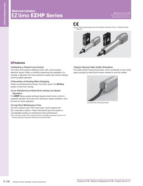
●Space-Saving Cable Outlet Orientation<br />
The cable outlet is facing downward, which contributes to the overall<br />
space savings by reducing the space needed to wire the cables.<br />
The cable outlet is facing downward.<br />
D-108 ORIENTAL MOTOR GENERAL CATALOG 2009/2010 Features D-108 / System Configuration D-109 / Product Line D-111
■System Configuration<br />
●Controller Mode<br />
Required Products (Sold separately)<br />
1Cable Set<br />
(➜ Page D-116)<br />
<strong>Motor</strong> Cables<br />
<strong>EZHP</strong> <strong>Series</strong><br />
Cylinder<br />
Accessories and Peripheral<br />
Equipment (Sold separately)<br />
3Sensor Set<br />
(➜ Page D-117)<br />
Actuator Communication Cables<br />
Battery,<br />
Battery Holder<br />
(Supplied with absolute<br />
type models.)<br />
(Connected by the customer)<br />
Linear Motion Controller<br />
AC Power<br />
Supply<br />
(Not supplied)<br />
4Sensor Extension Cables<br />
(➜ Page D-117)<br />
24 VDC<br />
Power Supply<br />
(For control)<br />
(Not supplied)<br />
2Teaching Pendant<br />
(➜ Page D-118)<br />
5I/O Cables<br />
(➜ Page D-119)<br />
Programmable<br />
Controller<br />
(Not supplied)<br />
No. Product Name Overview Page<br />
1<br />
2<br />
3<br />
4<br />
5<br />
Cable Set<br />
Teaching Pendant<br />
Sensor Set<br />
Sensor Extension Cables<br />
I/O Cables<br />
Cable for extending the wiring distance between the cylinder and linear motion controller (2 to 10 m).<br />
Each set consists of a motor cable and an actuator communication cable.<br />
This pendant (EZT1) lets you set and operate various data at your fingertips. Cable length 5 m.<br />
Three sets of sensors, sensor mounting brackets and cables with connector (2 m), as well as a shielding plate.<br />
Cable used for connection between the linear motion controller and the sensor (1 m, 2 m).<br />
Cable used for connection between the linear motion controller and the host controller (1 m, 2 m).<br />
D-116<br />
D-118<br />
D-117<br />
D-117<br />
D-119<br />
<strong>Motor</strong>ized Linear Slides <strong>Motor</strong>ized Cylinders Compact Linear Actuators Hollow Rotary Actuators<br />
Linear and Rotary Actuators Introduction EZS<br />
Accessories<br />
Installation EZC EZHC <strong>EZHP</strong><br />
Accessories<br />
Installation DRL<br />
Accessories<br />
Installation DG<br />
Accessories<br />
Installation<br />
●Example of System Configuration<br />
(Sold separately)<br />
<strong>EZHP</strong> <strong>Series</strong><br />
<strong>EZHP</strong>4A-05A<br />
Cable Set ✽1<br />
(2 m)<br />
CC02EZ2<br />
Teaching<br />
Pendant<br />
EZT1<br />
(Sold separately)<br />
I/O Cable<br />
(1 m)<br />
CC36D1-1<br />
✽1 <strong>Motor</strong> cable and actuator communication cable are available separately. ➜ Page D-116<br />
✽2 Not required if return to home operation is performed without sensors.<br />
Sensor Extension Cable ✽2<br />
(2 m)<br />
CC20D2-1<br />
Sensor Set ✽2<br />
(2 m)<br />
PAES-S<br />
● The system configuration shown above is an example. Other combinations are available<br />
Specifications, Characteristics D-112 / Dimensions D-114 / Connection and Operation D-100 / Cylinder and Controller Combinations D-114<br />
D-109
Linear and Rotary Actuators<br />
●Driver Mode<br />
An example of a single-axis system configuration with the EMP400 <strong>Series</strong> controller.<br />
Required Products (Sold separately)<br />
<strong>Motor</strong> Cables<br />
1Cable Set<br />
(➜ Page D-116)<br />
Actuator<br />
Communication<br />
Cables<br />
Controller (Sold separately)<br />
2Controller EMP400 <strong>Series</strong><br />
(➜ Page C-274)<br />
<strong>EZHP</strong> <strong>Series</strong><br />
Cylinder<br />
Linear Motion Controller<br />
Programmable<br />
Controller<br />
(Not supplied)<br />
Battery,<br />
Battery Holder<br />
(Supplied with absolute<br />
type models.)<br />
(Connected by the customer)<br />
Accessories and Peripheral<br />
Equipment (Sold separately)<br />
AC Power<br />
Supply<br />
(Not supplied)<br />
24 VDC<br />
Power Supply<br />
(For control)<br />
(Not supplied)<br />
4Driver – Sensor Cables<br />
(➜ Page D-119)<br />
3Sensor Set<br />
(➜ Page D-117)<br />
5Connector – Terminal<br />
Block Conversion Unit<br />
(➜ Page C-288)<br />
No. Product Name Overview Page<br />
1<br />
2<br />
3<br />
4<br />
5<br />
Cable Set<br />
Controller<br />
Sensor Set<br />
Driver – Sensor Cables<br />
Connector – Terminal Block Conversion Unit<br />
Cable for extending the wiring distance between the cylinder and linear motion controller (2 to 10 m).<br />
Each set consists of a motor cable and an actuator communication cable.<br />
This controller gives commands needed to drive the cylinder.<br />
Three sets of sensors, sensor mounting brackets and cables with connector (2 m), as well as a shielding plate.<br />
Cable for connecting the linear motion controller and the EMP <strong>Series</strong> controller (0.5 m).<br />
Set of terminal block and cable for connecting the EMP <strong>Series</strong> controller and the host controller (1 m).<br />
D-116<br />
C-274<br />
D-117<br />
D-119<br />
C-288<br />
●Example of System Configuration<br />
(Sold separately)<br />
Cable Set<br />
<strong>EZHP</strong> <strong>Series</strong><br />
✽<br />
(2 m)<br />
<strong>EZHP</strong>4A-05A CC02EZ2<br />
(Sold separately)<br />
Controller<br />
EMP401-1<br />
✽ <strong>Motor</strong> cable and actuator communication cable are available separately. ➜ Page D-116<br />
Driver – Sensor Cable<br />
(0.5 m)<br />
CC005EZ6-EMPD<br />
Sensor Set<br />
(2 m)<br />
PAES-S<br />
Connector – Terminal Block<br />
Conversion Unit (1 m)<br />
CC50T1<br />
● The system configuration shown above is an example. Other combinations are available<br />
D-110 ORIENTAL MOTOR GENERAL CATALOG 2009/2010 Features D-108 / System Configuration D-109 / Product Line D-111
■Product Number Code<br />
<strong>EZHP</strong> 4 A - 10 M I<br />
1 2 3 4 5 6<br />
■Product Line<br />
●Incremental Type<br />
◇Without Electromagnetic Brake<br />
Stroke<br />
Single-Phase 100-115 VAC<br />
Single-Phase 200-230 VAC<br />
Model Model Model<br />
50 mm <strong>EZHP</strong>4A-05I <strong>EZHP</strong>6A-05I <strong>EZHP</strong>6C-05I<br />
100 mm <strong>EZHP</strong>4A-10I <strong>EZHP</strong>6A-10I <strong>EZHP</strong>6C-10I<br />
200 mm <strong>EZHP</strong>4A-20I <strong>EZHP</strong>6A-20I <strong>EZHP</strong>6C-20I<br />
300 mm <strong>EZHP</strong>4A-30I <strong>EZHP</strong>6A-30I <strong>EZHP</strong>6C-30I<br />
◇With Electromagnetic Brake<br />
Stroke<br />
Single-Phase 100-115 VAC<br />
Single-Phase 200-230 VAC<br />
Model Model Model<br />
50 mm <strong>EZHP</strong>4A-05MI <strong>EZHP</strong>6A-05MI <strong>EZHP</strong>6C-05MI<br />
100 mm <strong>EZHP</strong>4A-10MI <strong>EZHP</strong>6A-10MI <strong>EZHP</strong>6C-10MI<br />
200 mm <strong>EZHP</strong>4A-20MI <strong>EZHP</strong>6A-20MI <strong>EZHP</strong>6C-20MI<br />
300 mm <strong>EZHP</strong>4A-30MI <strong>EZHP</strong>6A-30MI <strong>EZHP</strong>6C-30MI<br />
●Absolute Type<br />
◇Without Electromagnetic Brake<br />
Stroke<br />
Single-Phase 100-115 VAC<br />
Single-Phase 200-230 VAC<br />
Model Model Model<br />
50 mm <strong>EZHP</strong>4A-05A <strong>EZHP</strong>6A-05A <strong>EZHP</strong>6C-05A<br />
100 mm <strong>EZHP</strong>4A-10A <strong>EZHP</strong>6A-10A <strong>EZHP</strong>6C-10A<br />
200 mm <strong>EZHP</strong>4A-20A <strong>EZHP</strong>6A-20A <strong>EZHP</strong>6C-20A<br />
300 mm <strong>EZHP</strong>4A-30A <strong>EZHP</strong>6A-30A <strong>EZHP</strong>6C-30A<br />
◇With Electromagnetic Brake<br />
Stroke<br />
Single-Phase 100-115 VAC<br />
Single-Phase 200-230 VAC<br />
Model Model Model<br />
50 mm <strong>EZHP</strong>4A-05MA <strong>EZHP</strong>6A-05MA <strong>EZHP</strong>6C-05MA<br />
100 mm <strong>EZHP</strong>4A-10MA <strong>EZHP</strong>6A-10MA <strong>EZHP</strong>6C-10MA<br />
200 mm <strong>EZHP</strong>4A-20MA <strong>EZHP</strong>6A-20MA <strong>EZHP</strong>6C-20MA<br />
300 mm <strong>EZHP</strong>4A-30MA <strong>EZHP</strong>6A-30MA <strong>EZHP</strong>6C-30MA<br />
The following items are included in each product.<br />
Cylinder, Linear Motion Controller, Operating Manual, Mounting Bracket for Controller,<br />
Hexagonal Nut, User I/O Connector, Sensor I/O Connector, Battery ✽ , Battery Holder ✽<br />
✽ Only for absolute type<br />
1 <strong>Series</strong> <strong>EZHP</strong>: <strong>EZHP</strong> <strong>Series</strong><br />
2 Cylinder Size<br />
3 Power Supply Input A: Single-Phase 100-115 VAC C: Single-Phase 200-230 VAC<br />
4 Stroke 05: 50 mm 10: 100 mm 20: 200 mm 30: 300 mm<br />
Electromagnetic Brake Blank: Without Electromagnetic Brake<br />
5<br />
M: With Electromagnetic Brake<br />
6 Type I: Incremental Type A: Absolute Type<br />
<strong>Motor</strong>ized Linear Slides <strong>Motor</strong>ized Cylinders Compact Linear Actuators Hollow Rotary Actuators<br />
Linear and Rotary Actuators Introduction EZS<br />
Accessories<br />
Installation EZC EZHC <strong>EZHP</strong><br />
Accessories<br />
Installation DRL<br />
Accessories<br />
Installation DG<br />
Accessories<br />
Installation<br />
Specifications, Characteristics D-112 / Dimensions D-114 / Connection and Operation D-100 / Cylinder and Controller Combinations D-114<br />
D-111
Linear and Rotary Actuators<br />
■Specifications<br />
●Cylinder Specifications<br />
Model<br />
Incremental Type<br />
Absolute Type<br />
<strong>Motor</strong> Type<br />
Drive Method<br />
Electromagnetic Brake<br />
Speed Range<br />
mm/s<br />
Max. Transportable Mass<br />
Max. Acceleration<br />
Max. Thrust Force<br />
kg<br />
m/s 2<br />
Horizontal Direction ✽<br />
Vertical Direction<br />
Horizontal Direction<br />
Vertical Direction<br />
N<br />
Push Force<br />
N<br />
Power ON<br />
Max. Holding Force N Power OFF<br />
Electromagnetic Brake<br />
Repetitive Positioning Accuracy mm<br />
Resolution<br />
mm<br />
Lead<br />
mm<br />
Stroke<br />
mm<br />
<strong>EZHP</strong>4A-□I<br />
<strong>EZHP</strong>4A-□MI <strong>EZHP</strong>6A-□I, <strong>EZHP</strong>6C-□I <strong>EZHP</strong>6A-□MI, <strong>EZHP</strong>6C-□MI<br />
<strong>EZHP</strong>4A-□A<br />
<strong>EZHP</strong>4A-□MA <strong>EZHP</strong>6A-□A, <strong>EZHP</strong>6C-□A <strong>EZHP</strong>6A-□MA, <strong>EZHP</strong>6C-□MA<br />
Stepping <strong>Motor</strong> with Built-In Rotor-Position Sensor<br />
Rolled Ball Screw<br />
Not equipped<br />
Equipped<br />
Not equipped<br />
Equipped<br />
∼200<br />
∼300 ∼200<br />
∼300 ∼200 ∼300 ∼200<br />
∼300<br />
−<br />
−<br />
− 14 9<br />
− 30 12<br />
−<br />
−<br />
140<br />
− 2.5<br />
−<br />
110<br />
140 110 400 147 400 147<br />
140 (Speed: 6 mm/s or less) 400 (Speed: 6 mm/s or less)<br />
140<br />
−<br />
±0.02<br />
0.01<br />
6<br />
50, 100, 200, 300<br />
Cylinder Mass [Stroke: Mass]<br />
50: 1.7 (1.9) 100: 2.0 (2.2)<br />
50: 3.3 (3.7) 100: 3.7 (4.1)<br />
Figure in the parentheses shows the kg<br />
200: 2.5 (2.7) 300: 3.0 (3.2)<br />
200: 4.6 (5.0) 300: 5.6 (6.0)<br />
mass of the model with electromagnetic brake.<br />
●Enter the stroke length in the box ( □) within the model name.<br />
✽ In a horizontal direction, the value cannot be shown because it varies by frictional resistance of the load supporting mechanism. Always provide an external anti-spin mechanism, such as a guide.<br />
Installation ➜ Page D-121<br />
How to read specifications ➜ Page D-70<br />
140<br />
− 2.5<br />
−<br />
400<br />
−<br />
400<br />
● Correlation Diagram of<br />
Speed and Thrust Force<br />
◇Horizontal Direction/Vertical Direction<br />
Thrust Force [N]<br />
500<br />
400<br />
300<br />
200<br />
100<br />
0<br />
<strong>EZHP</strong>6<br />
<strong>EZHP</strong>4<br />
0 100 200 300<br />
Speed [mm/s]<br />
● Correlation Diagram of<br />
Speed and Transportable Mass<br />
◇Vertical Direction<br />
Transportable Mass [kg]<br />
30<br />
25<br />
20<br />
15<br />
10<br />
5<br />
0<br />
<strong>EZHP</strong>6<br />
<strong>EZHP</strong>4<br />
0 100 200 300<br />
Speed [mm/s]<br />
●Push Force<br />
Push force can be set through "Push current setting" in a program<br />
mode.<br />
◇<strong>EZHP</strong>4<br />
Push Force [N]<br />
180<br />
160<br />
140<br />
120<br />
100<br />
80<br />
60<br />
40<br />
20<br />
0<br />
0 5 10 15 20 25 30 35 40 45 50 55<br />
Push Current [%]<br />
◇<strong>EZHP</strong>6<br />
Push Force [N]<br />
500<br />
400<br />
300<br />
200<br />
100<br />
0<br />
0 5 10 15 20 25 30 35 40 45<br />
Push Current [%]<br />
●Positioning Distance – Positioning Time<br />
The positioning time (reference value) can be checked from the<br />
positioning distance.<br />
The graphs below represent the characteristics when operated at<br />
maximum acceleration and maximum speed.<br />
◇Horizontal Direction/Vertical Direction<br />
Positioning Time [s]<br />
3.5<br />
3.0<br />
2.5<br />
2.0<br />
1.5<br />
1.0<br />
0.5<br />
0<br />
300 mm/s<br />
200 mm/s<br />
100 mm/s<br />
0 100 200 300<br />
Positioning Distance [mm]<br />
●The starting speed should be 3 mm/s or less.<br />
Enlargement of Positioning Distance under 100 mm<br />
Positioning Time [s]<br />
1.2<br />
1.0<br />
0.8<br />
0.6<br />
0.4<br />
0.2<br />
0<br />
300 mm/s<br />
200 mm/s<br />
100 mm/s<br />
0 20 40 60 80 100<br />
Positioning Distance [mm]<br />
Notes:<br />
●The above value is a reference, not guaranteed.<br />
●When the cylinder is used in a vertical direction, an external force calculated by multiplying<br />
the mass of the load by the rate of gravitational acceleration is applied. Therefore, the cylinder<br />
push force must be set so as to accommodate this external force. Measure the push force<br />
using an actual load, and set an appropriate push current.<br />
D-112 ORIENTAL MOTOR GENERAL CATALOG 2009/2010 Features D-108 / System Configuration D-109 / Product Line D-111
●Specifications of Linear Motion Controller<br />
◇Controller Mode<br />
Model<br />
Type<br />
Number of Control Axes<br />
Control Power<br />
Power<br />
Supply<br />
Main Power<br />
Input<br />
Positioning<br />
Data<br />
Positioning<br />
Control<br />
Control Modes<br />
Operation Modes<br />
Input<br />
Signals<br />
Output<br />
Signals<br />
Voltage<br />
Frequency<br />
Current<br />
Setting Mode<br />
Number<br />
Setting Method<br />
Mode<br />
Travel Amount Setting Range<br />
Starting Speed Setting Range<br />
Operating Speed Setting Range<br />
Acceleration/Deceleration Rate<br />
Setting Range<br />
Input Mode<br />
START<br />
STOP<br />
HOME/PRESET<br />
FREE<br />
M0∼M5<br />
REQ<br />
FWD<br />
RVS<br />
ACL/CK<br />
Output Mode<br />
ALM<br />
END/OUTR<br />
MOVE<br />
AREA/OUT0<br />
T-UP/OUT1<br />
ASG1, BSG1<br />
ASG2, BSG2<br />
Protective Functions<br />
Indicators (LED)<br />
Cooling Method<br />
Mass<br />
EZMC13I-A/EZMC13A-A<br />
EZMC24I-A/EZMC24A-A<br />
Stored data type<br />
1 axis<br />
24 VDC±10% 1.0 A (Controller only: 0.5 A) ✽<br />
Single-Phase 100-115 VAC −15%, +10%<br />
50/60 Hz<br />
3.3 A<br />
5.0 A<br />
Absolute mode (absolute-position specification), Incremental mode (relative-position specification)<br />
63<br />
Data is set using the accessory teaching pendant (EZT1). (Stored in EEPROM)<br />
Sequential positioning, Selective positioning<br />
−83886.08∼+83886.07 mm (value set in units of 0.01 mm)<br />
0.01∼250.00 mm/s (value set in units of 0.01 mm/s)<br />
0.01∼300.00 mm/s (value set in units of 0.01 mm/s)<br />
0.01∼100.00 m/s 2 (value set in units of 0.01 m/s 2 )<br />
EZMC12I-C/EZMC12A-C<br />
Single-Phase 200-230 VAC −15%, +10%<br />
· External input mode (EXT): In this mode, operation by external signal, command position, I/O condition and alarm condition can be monitored.<br />
· Program mode (PRG): In this mode, operation data can be created, changed or cleared.<br />
· Parameter mode (PAR): In this mode, operation parameters and function setting parameters can be set or changed.<br />
· Test mode (TST): In this mode, manual operation and I/O check can be performed.<br />
Positioning operation, Return to home operation, Linked operation (a maximum of 4 data), Push-motion operation, Continuous operation<br />
24 VDC Photocoupler insulation input, Input resistance: 4.7 kΩ (START, STOP, HOME/PRESET, FREE, M0∼M5, REQ, ACL/CK)<br />
5 VDC Photocoupler insulation input, Input resistance: 180 Ω or 24 VDC Photocoupler insulation input, Input resistance: 2.7 kΩ (FWD, RVS)<br />
Start the positioning operation.<br />
Stop the positioning operation and the return to home operation.<br />
HOME: Start the return to home operation. PRESET: Preset the current position.<br />
Stop motor excitation and release the electromagnetic brake.<br />
Select the step No.<br />
Request the current position output.<br />
Move the cylinder rod to the counter-motor side.<br />
Move the cylinder rod to the motor side.<br />
ACL: Cancel the protective function currently active. CK: Used when the current position is output.<br />
Transistor output linked to photocoupler (24 VDC, 15 mA or less), Line driver output<br />
This signal is output when a protective function has been activated.<br />
END: Turn ON when the positioning operation or return to home operation has ended. OUTR: Turn ON when current position output is ready.<br />
This signal is output when the cylinder is moving.<br />
AREA: This output notifies that the moving part of the cylinder is staying inside a specified area. OUT0: Output current position.<br />
T-UP: Output when the push-motion operation has ended. OUT1: Output current position.<br />
Output the position of the cylinder rod via pulse signal. (Open-collector output)<br />
Output the position of the cylinder rod via pulse signal. (Line driver output)<br />
Excessive position deviation, Overcurrent protection, Overvoltage protection, Overheat protection, Overload, <strong>Motor</strong> overheat protection,<br />
Sensor error, Overspeed, Nonvolatile memory error, etc.<br />
Control power supply, Alarm<br />
Natural ventilation<br />
0.8 kg<br />
✽ Take into account safety margin of +0.2 A for the teaching pendant, and/or +0.3 A for the electromagnetic brake type.<br />
◇Driver Mode<br />
Power<br />
Supply<br />
Input<br />
Model<br />
Control Power<br />
Maximum Response Frequency<br />
Input<br />
Signals<br />
Output<br />
Signals<br />
Main Power<br />
Input Mode<br />
FP<br />
RP<br />
ACL/CK<br />
FREE<br />
C.OFF<br />
PRESET<br />
REQ<br />
Output Mode<br />
TIM./OUT0<br />
OUT1<br />
ALM<br />
END/OUTR<br />
ASG1, BSG1<br />
ASG2, BSG2<br />
Protective Functions<br />
Indicators (LED)<br />
Cooling Method<br />
Mass<br />
Voltage<br />
Frequency<br />
Current<br />
EZMC13I-A/EZMC13A-A<br />
EZMC24I-A/EZMC24A-A<br />
EZMC12I-C/EZMC12A-C<br />
24 VDC ±10% 1.0 A (Controller only: 0.5 A) ✽<br />
Single-Phase 100-115 VAC −15%, +10%<br />
Single-Phase 200-230 VAC −15%, +10%<br />
50/60 Hz<br />
3.3 A<br />
5.0 A<br />
3.0 A<br />
80 kHz (When the pulse duty is 50%)<br />
5 VDC Photocoupler insulation input, Input resistance: 180 Ω or 24 VDC Photocoupler insulation input, Input resistance: 2.7 kΩ (FP, RP)<br />
24 VDC Photocoupler insulation input, Input resistance: 4.7 kΩ (ACL/CK, FREE, C.OFF, PRESET, REQ)<br />
Operation command pulse input (The operation command pulse input in counter-motor direction in the 2-pulse input mode)<br />
Pulse width: 2 μs minimum, Pulse rise/fall: 2 μs maximum (Negative logic pulse input)<br />
Direction of movement input (The operation command pulse input in motor direction in the 2-pulse input mode)<br />
Pulse width: 2 μs minimum, Pulse rise/fall: 2 μs maximum (Negative logic pulse input)<br />
ACL: Cancel the protective function currently active. CK: Used when the current position is output.<br />
Stop motor excitation and release the electromagnetic brake.<br />
The current flow to the motor is cut off.<br />
Preset the current position.<br />
Request the current position output.<br />
Transistor output linked to photocoupler (24 VDC, 15 mA or less), Line driver output<br />
TIM.: Signal is output when the excitation sequence is at step "0."<br />
(A TIM. signal is output each time the rod moves by 0.12 mm.) OUT0: Output current position.<br />
Output current position.<br />
This signal is output when a protective function has been activated.<br />
END: Turn ON when the positioning operation or return to home operation has ended. OUTR: Turn ON when current position output is ready.<br />
Output the position of the cylinder rod via pulse signal. (Open-collector output)<br />
Output the position of the cylinder rod via pulse signal. (Line driver output)<br />
Excessive position deviation, Overcurrent protection, Overvoltage protection, Overheat protection, Overload, <strong>Motor</strong> overheat protection, Sensor error,<br />
Overspeed, Nonvolatile memory error, etc.<br />
Control power supply, Alarm<br />
Natural ventilation<br />
0.8 kg<br />
✽ Take into account safety margin of +0.2 A for the teaching pendant, and/or +0.3 A for the electromagnetic brake type.<br />
3.0 A<br />
<strong>Motor</strong>ized Linear Slides <strong>Motor</strong>ized Cylinders Compact Linear Actuators Hollow Rotary Actuators<br />
Linear and Rotary Actuators Introduction EZS<br />
Accessories<br />
Installation EZC EZHC <strong>EZHP</strong><br />
Accessories<br />
Installation DRL<br />
Accessories<br />
Installation DG<br />
Accessories<br />
Installation<br />
Specifications, Characteristics D-112 / Dimensions D-114 / Connection and Operation D-100 / Cylinder and Controller Combinations D-114<br />
D-113
Linear and Rotary Actuators<br />
■General Specifications<br />
This is the value after rated operation under normal ambient temperature and humidity.<br />
Item <strong>Motor</strong> Linear Motion Controller<br />
Insulation Resistance<br />
100 MΩ or more when 500 VDC megger is applied between the following places:<br />
· <strong>Motor</strong>/Sensor windings – Case<br />
· Case – Windings of electromagnetic brake (Only for electromagnetic brake type)<br />
100 MΩ or more when 500 VDC megger is applied between the following places:<br />
· Signal I/O, Control power supply, PE – Main power supply terminal<br />
· Signal I/O, Control power supply, PE – <strong>Motor</strong> output terminal<br />
· Signal I/O, Control power supply, PE – Battery input terminal<br />
Dielectric Strength<br />
Sufficient to withstand the following for 1 minute:<br />
<strong>EZHP</strong>4<br />
· <strong>Motor</strong>/Sensor windings – Case 1.0 kVAC 50 Hz<br />
· Case – Windings of electromagnetic brake<br />
(Only for electromagnetic brake type) 1.0 kVAC 50 Hz<br />
<strong>EZHP</strong>6<br />
· <strong>Motor</strong>/Sensor windings – Case 1.5 kVAC 50 Hz<br />
· Case – Windings of electromagnetic brake<br />
(Only for electromagnetic brake type) 1.0 kVAC 50 Hz<br />
Ambient Temperature<br />
0∼+40°C (non-freezing)<br />
Ambient Humidity<br />
85% or less (non-condensing)<br />
Note:<br />
●Do not measure insulation resistance or perform the dielectric strength test while the cylinder and linear motion controller are connected.<br />
■Battery Specifications<br />
(For the absolute type only)<br />
Model<br />
Battery Type<br />
Nominal Voltage<br />
Rated Capacity<br />
Mass<br />
Life<br />
Charge Time<br />
Data Retention Period<br />
Ambient Temperature<br />
Ambient Humidity<br />
PAEZ-BT2<br />
Cylindrical sealed nickel-cadmium storage cell<br />
2.4 V<br />
2000 mAh<br />
180 g<br />
Approx. 4 years ✽1<br />
48 hours ✽1<br />
Approx. 360 hours (15 days) ✽1✽2<br />
0∼+40˚C (non-freezing)<br />
20∼85% (non-condensing)<br />
✽ 1 At an ambient temperature of 20˚C<br />
✽ 2 After the power is cut off with the battery fully charged.<br />
■Dimensions<br />
●Cylinder<br />
◇<strong>EZHP</strong>4<br />
Unit = mm<br />
Cylinder Model L1 L2 L3 L4 DXF<br />
<strong>EZHP</strong>4A-05 270.5 130<br />
D396<br />
104 50<br />
<strong>EZHP</strong>4A-05M 300.5 160 D397<br />
<strong>EZHP</strong>4A-10 320.5 130<br />
D398<br />
154 100<br />
<strong>EZHP</strong>4A-10M 350.5 160 D399<br />
<strong>EZHP</strong>4A-20 420.5 130<br />
D400<br />
254 200<br />
<strong>EZHP</strong>4A-20M 450.5 160 D401<br />
<strong>EZHP</strong>4A-30 520.5 130<br />
D402<br />
354 300<br />
<strong>EZHP</strong>4A-30M 550.5 160 D403<br />
Sufficient to withstand the following for 1 minute:<br />
· Signal I/O, Control power supply – Main power supply terminal 1.8 kVAC<br />
· Signal I/O, Control power supply – <strong>Motor</strong> output terminal 1.8 kVAC<br />
· Signal I/O, Control power supply – Battery input terminal 1.8 kVAC<br />
· PE – Main power supply terminal 1.5 kVAC<br />
· PE – <strong>Motor</strong> output terminal 1.5 kVAC<br />
· PE – Battery input terminal 1.5 kVAC<br />
■List of Cylinder and Controller<br />
Combinations<br />
Model names for cylinder and linear motion controller combinations<br />
are shown below.<br />
Type<br />
Incremental<br />
Type<br />
Absolute<br />
Type<br />
Incremental<br />
Type<br />
Absolute<br />
Type<br />
Electromagnetic<br />
Brake<br />
Model<br />
Cylinder Model<br />
Linear Motion<br />
Controller Model<br />
Not equipped <strong>EZHP</strong>4A-□I <strong>EZHP</strong>4A-□<br />
Equipped <strong>EZHP</strong>4A-□MI <strong>EZHP</strong>4A-□M<br />
EZMC13I-A<br />
Not equipped <strong>EZHP</strong>4A-□A <strong>EZHP</strong>4A-□<br />
Equipped <strong>EZHP</strong>4A-□MA <strong>EZHP</strong>4A-□M<br />
EZMC13A-A<br />
Not equipped<br />
<strong>EZHP</strong>6A-□I <strong>EZHP</strong>6A-□ EZMC24I-A<br />
<strong>EZHP</strong>6C-□I <strong>EZHP</strong>6C-□ EZMC12I-C<br />
Equipped<br />
<strong>EZHP</strong>6A-□MI <strong>EZHP</strong>6A-□M EZMC24I-A<br />
<strong>EZHP</strong>6C-□MI <strong>EZHP</strong>6C-□M EZMC12I-C<br />
Not equipped<br />
<strong>EZHP</strong>6A-□A <strong>EZHP</strong>6A-□ EZMC24A-A<br />
<strong>EZHP</strong>6C-□A <strong>EZHP</strong>6C-□ EZMC12A-C<br />
Equipped<br />
<strong>EZHP</strong>6A-□MA <strong>EZHP</strong>6A-□M EZMC24A-A<br />
<strong>EZHP</strong>6C-□MA <strong>EZHP</strong>6C-□M EZMC12A-C<br />
●Enter the stroke length in the box ( □) within the model name.<br />
32<br />
<strong>Motor</strong> Cable ϕ7.7, 250 mm Length<br />
Actuator Communication Cable ϕ7.7, 250 mm Length<br />
L1<br />
10 23.5<br />
Protective Earth Terminal M4 27.5 Rod Home Position<br />
L2 L3 58.5<br />
2<br />
Rod Limit Position<br />
56.5<br />
5<br />
M14 P1.5<br />
0<br />
ϕ25−0.021<br />
+0.061<br />
ϕ35+0.034<br />
L4<br />
(Effective<br />
Stroke) 1<br />
Rod Limit<br />
Position<br />
42<br />
22<br />
45˚<br />
22<br />
42<br />
52<br />
45˚<br />
ϕ43<br />
24.5<br />
57 3.7<br />
4×M5 P0.8×15 Deep<br />
●Nut (1 piece, included)<br />
M14 P1.5<br />
23.36<br />
21<br />
12.8<br />
D-114 ORIENTAL MOTOR GENERAL CATALOG 2009/2010 Features D-108 / System Configuration D-109 / Product Line D-111
◇<strong>EZHP</strong>6<br />
Cylinder Model L1 L2 L3 L4 DXF<br />
<strong>EZHP</strong>6□-05 289 138<br />
D404<br />
106 50<br />
<strong>EZHP</strong>6□-05M 324 173 D405<br />
<strong>EZHP</strong>6□-10 339 138<br />
D406<br />
156 100<br />
<strong>EZHP</strong>6□-10M 374 173 D407<br />
<strong>EZHP</strong>6□-20 439 138<br />
D408<br />
256 200<br />
<strong>EZHP</strong>6□-20M 474 173 D409<br />
<strong>EZHP</strong>6□-30 539 138<br />
D410<br />
356 300<br />
<strong>EZHP</strong>6□-30M 574 173 D411<br />
●Enter the power supply voltage A or C in the box (□) within the model name.<br />
32<br />
<strong>Motor</strong> Cable ϕ7.7, 250 mm Length<br />
Actuator Communication Cable ϕ7.7, 250 mm Length<br />
●Nut (1 piece, included)<br />
M18 P1.5<br />
27<br />
29.56<br />
15.8<br />
●Linear Motion Controller<br />
EZMC13I-A, EZMC24I-A, EZMC12I-C<br />
EZMC13A-A, EZMC24A-A, EZMC12A-C<br />
Mass: 0.8 kg<br />
D487<br />
4×M3 P0.5<br />
25 10<br />
6<br />
134<br />
10<br />
Slits<br />
L2<br />
L1<br />
Protective Earth Terminal M4 27.5 Rod Home Position<br />
L3 95.5<br />
122 41 max.<br />
M4<br />
11<br />
16<br />
43.5 33.3<br />
18<br />
150<br />
6.2<br />
7.62 Pitch<br />
2<br />
5 max.<br />
3−M3<br />
15<br />
30<br />
Rod Limit Position<br />
93.5<br />
45<br />
5<br />
M18 P1.5<br />
0<br />
ϕ35−0.025<br />
+0.069<br />
ϕ48+0.034<br />
L4<br />
(Effective<br />
Stroke)<br />
60<br />
32<br />
Rod Limit<br />
1 Position<br />
● Mounting Bracket<br />
(2 pieces, included)<br />
45˚<br />
10 10<br />
32<br />
60<br />
73<br />
25<br />
45˚<br />
ϕ57<br />
32.5<br />
3.7<br />
74<br />
4×M6 P1×15 Deep<br />
4.5 3<br />
25<br />
2×ϕ3.5 Countersink<br />
45<br />
43<br />
●Battery<br />
(Supplied with absolute type. Battery holder provided.)<br />
Mass: 0.18 kg<br />
D488<br />
37.2<br />
31.5±2.5<br />
2-R18.6<br />
60±2.5<br />
25<br />
●Control I/O Connector (Included)<br />
Case: 54331-1361 (MOLEX)<br />
Connector: 54306-3619 (MOLEX)<br />
●Sensor I/O Connector (Included)<br />
Case: 54331-1201 (MOLEX)<br />
Connector: 54306-2019 (MOLEX)<br />
5<br />
3<br />
79.2<br />
<strong>Motor</strong>ized Linear Slides <strong>Motor</strong>ized Cylinders Compact Linear Actuators Hollow Rotary Actuators<br />
Linear and Rotary Actuators Introduction EZS<br />
Accessories<br />
Installation EZC EZHC <strong>EZHP</strong><br />
Accessories<br />
Installation DRL<br />
Accessories<br />
Installation DG<br />
Accessories<br />
Installation<br />
300±15<br />
15<br />
4.5<br />
13 11<br />
56±2.5<br />
7.5<br />
8-R2.25<br />
■Connection and Operation<br />
Common to EZHC <strong>Series</strong>. Refer to page D-100.<br />
Specifications, Characteristics D-112 / Dimensions D-114 / Connection and Operation D-100 / Cylinder and Controller Combinations D-114<br />
D-115


