

FBL II Series - Oriental Motor
FBL II Series - Oriental Motor
FBL II Series - Oriental Motor

Create successful ePaper yourself
Turn your PDF publications into a flip-book with our unique Google optimized e-Paper software.
Speed Control Systems<br />
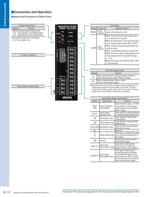
■Connection and Operation<br />
●Names and Functions of Driver Parts<br />
Internal Potentiometer<br />
Display<br />
Function<br />
SPEED Internal Speed Potentiometer<br />
S.S. Acceleration Time Potentiometer ✽<br />
S.D. Deceleration Time Potentiometer ✽<br />
✽ Acceleration/Deceleration Time Setting:<br />
0.5∼15 sec. (3000 r/min)<br />
For <strong>Motor</strong> Connector<br />
Display<br />
POWER<br />
ALARM<br />
Function<br />
Power<br />
Indicator<br />
LED Display<br />
Lighting Condition<br />
Lights when the power is ON.<br />
●When the motor load exceeds rated torque<br />
for a minimum of 5 seconds.<br />
●When the temperature of the heat sink inside<br />
driver exceeds approximately 90°C (194°F).<br />
●When a load exceeding the permissible load<br />
Alarm<br />
Indicator inertia is driven.<br />
●When a gravitational operation is performed.<br />
●When the power supply voltage applied to the<br />
driver dropped below the specified voltage<br />
(−10%).<br />
●When the sensor wire inside the motor cable<br />
is disconnected.<br />
Power Supply Terminal Block<br />
I/O Power Supply Switch<br />
Display<br />
Function<br />
When controlling from a programmable controller or<br />
EXT.<br />
other external power supply. (Factory setting)<br />
When controlling with a relay or switch.<br />
INT.<br />
(Driver built-in power supply)<br />
● When the switch is set to EXT., the input circuit is insulated by the<br />
photocoupler. However when the switch is set to INT., the input<br />
circuit is not insulated, so the system will not work, even if an input<br />
signal is input, unless GND is connected to a controller.<br />
Input/Output Signal Terminal Block<br />
Display Signal Name Function<br />
INPUT<br />
COM<br />
EXT.VR.<br />
CW<br />
CCW<br />
Power Supply for<br />
Input Signals<br />
Speed Setting<br />
Selection Input<br />
CW Rotation Input<br />
CCW Rotation Input<br />
SLOW DOWN Deceleration Input<br />
N.C.<br />
—<br />
H<br />
M Speed Setting Input<br />
L<br />
GND Ground<br />
SPEED OUT<br />
ALARM OUT<br />
Speed Output<br />
(Open-Collector Output)<br />
Alarm Output<br />
(Open-Collector Output)<br />
External power supply +24 VDC<br />
A connection is not necessary<br />
when using the driver's built-in<br />
power supply.<br />
Input signal for selecting internal<br />
or external speed potentiometer.<br />
Input signal for selecting CW<br />
rotation/stop.<br />
Input signal for selecting CCW<br />
rotation/stop.<br />
Input terminal for decelerating<br />
the motor to a stop.<br />
Not used.<br />
Used when controlling the speed<br />
by an external potentiometer or<br />
DC voltage.<br />
Common ground terminal for<br />
input/output signals.<br />
Used when monitoring the<br />
motor speed; 12 pulses are<br />
output for each motor rotation.<br />
This signal is output when a<br />
protective function is activated.<br />
The ALARM LED lights and the<br />
motor coasts to a stop. To reset,<br />
turn off the power for 30 seconds,<br />
then turn the power on again.<br />
B-112 ORIENTAL MOTOR GENERAL CATALOG 2009/2010 Features B-104 / System Configuration B-105 / Product Line B-106 / Specifications B-107


