


You also want an ePaper? Increase the reach of your titles
YUMPU automatically turns print PDFs into web optimized ePapers that Google loves.
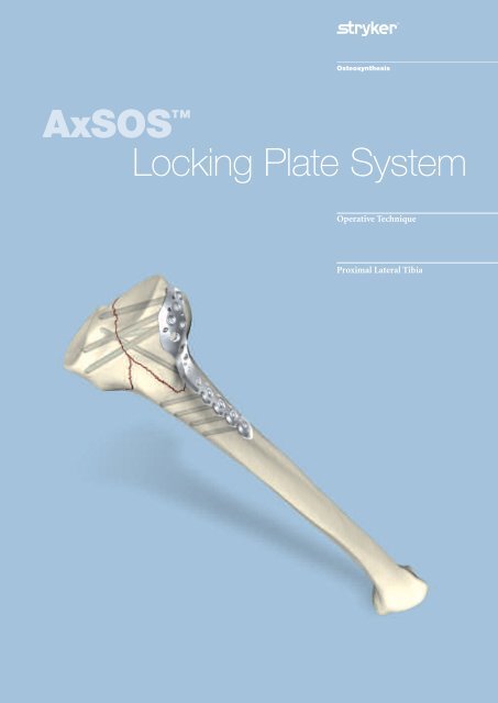
AxSOS <br />
Locking Plate System<br />
Operative Technique<br />
<strong>Proximal</strong> Lateral <strong>Tibia</strong><br />
1
Introduction<br />
The AxSOS Locking Plate System<br />
is designed to treat periarticular<br />
or intra-articular fractures of the<br />
<strong>Proximal</strong> Humerus, Distal Femur,<br />
<strong>Proximal</strong> <strong>Tibia</strong> and the Distal <strong>Tibia</strong>.<br />
The system design is based on clinical<br />
input from an international panel of<br />
experienced surgeons, data from<br />
literature, and both practical and<br />
biomechanical testing. The anatomical<br />
shape, the fixed screw trajectory,<br />
and high surface quality take into<br />
account the current demands of<br />
clinical physicians for appropriate<br />
fixation, high fatigue strength,<br />
and minimal soft tissue damage.<br />
<strong>Proximal</strong> Lateral <strong>Tibia</strong>l Plate<br />
This Operative Technique contains a<br />
simple step-by-step procedure for the<br />
implantation of the <strong>Proximal</strong> Lateral<br />
<strong>Tibia</strong>l Plate.<br />
<strong>Proximal</strong> Humeral Plate<br />
Distal Lateral Femoral Plate<br />
Distal Medial <strong>Tibia</strong>l Plate<br />
Distal Anterolateral <strong>Tibia</strong>l Plate<br />
2
Features & Benefits<br />
System<br />
• The <strong>Proximal</strong> Lateral <strong>Tibia</strong>l Plate is<br />
designed with divergent fixed-angled<br />
screw trajectories which provide<br />
optimal biomechanical stability.<br />
This helps prevent loss of reduction.<br />
Instruments<br />
• Simple technique, easy<br />
instrumentation with minimal<br />
components.<br />
• Compatible with MIPO<br />
(Minimally Invasive Plate<br />
Osteosynthesis) technique using<br />
state of the art instrumentation.<br />
Range<br />
• Longer plates cover a wider range<br />
of fractures.<br />
Monoaxial holes (5)<br />
• Allow axially stable screw placement,<br />
bringing stability to construct.<br />
Aiming Block<br />
• Facilitates the placement of the<br />
Drill Sleeve.<br />
K-Wire/Reduction/Suture holes<br />
• Primary/temporary plate and<br />
fracture fixation.<br />
• Anchor point for soft tissue<br />
re-attachment.<br />
Anatomically contoured<br />
• Little or no bending required.<br />
• Reduced OR time.<br />
Innovative Locking Screw design<br />
• Screw is guided into plate.<br />
• Reduced potential for cross threading<br />
and cold welding.<br />
Unthreaded Freedom Holes<br />
• Freehand placement of screws.<br />
• Lag Screw possibility.<br />
Kick-Stand Screw<br />
• Aimed at posterior/medial fragment<br />
to provide strong triangular fixation.<br />
‘Waisted’ plate shape<br />
• Uniform load transfer.<br />
Rounded & Tapered Plate End<br />
• Helps facilitate sliding of plates<br />
sub-muscularly.<br />
Shaft Holes - Standard or Locking<br />
• Bi-directional shaft holes.<br />
• Compression, neutral or<br />
buttress fixation.<br />
• Accept Standard 3.5/4.0mm<br />
SPS screws.<br />
• Accept Locking Insert for axially<br />
stable screws.<br />
3
Relative Indications & Contraindications<br />
Relative Indication<br />
The indication for use of this internal<br />
fixation device includes metaphyseal<br />
extra and intra articular fractures of<br />
the proximal <strong>Tibia</strong>.<br />
Relative Contraindications<br />
The physician's education, training and<br />
professional judgement must be relied<br />
upon to choose the most appropriate<br />
device and treatment. The following<br />
contraindications may be of a relative<br />
or absolute nature, and must be taken<br />
into account by the attending surgeon:<br />
• Any active or suspected latent<br />
infection or marked local<br />
inflammation in or about the<br />
affected area.<br />
• Compromised vascularity that would<br />
inhibit adequate blood supply to the<br />
fracture or the operative site.<br />
• Bone stock compromised by disease,<br />
infection or prior implantation that<br />
can not provide adequate support<br />
and/or fixation of the devices.<br />
• Material sensitivity, documented<br />
or suspected.<br />
• Obesity. An overweight or obese<br />
patient can produce loads on the<br />
implant that can lead to failure of<br />
the fixation of the device or to<br />
failure of the device itself.<br />
• Patients having inadequate tissue<br />
coverage over the operative site.<br />
• Implant utilisation that would<br />
interfere with anatomical structures<br />
or physiological performance.<br />
• Any mental or neuromuscular<br />
disorder which would create an<br />
unacceptable risk of fixation failure or<br />
complications in postoperative care.<br />
• Other medical or surgical conditions<br />
which would preclude the potential<br />
benefit of surgery.<br />
Detailed information is included in<br />
the instructions for use being attached<br />
to every implant.<br />
See package insert for a complete<br />
list of potential adverse effects and<br />
contraindications. The surgeon must<br />
discuss all relevant risks, including the<br />
finite lifetime of the device, with the<br />
patient, when necessary.<br />
Caution: Bone Screws are not intended<br />
for screw attachment or fixation to<br />
the posterior elements (pedicles) of<br />
the cervical, thoracic or lumbar spine.<br />
4
Operative Technique<br />
General Guidelines<br />
Patient Positioning:<br />
Surgical Approach:<br />
Instrument/Screw Set:<br />
Supine with option to flex the knee<br />
Lateral Parapatellar<br />
4.0mm<br />
Reduction<br />
Anatomical reduction of the fracture<br />
should be performed either by<br />
direct visualisation with the help of<br />
percutaneous clamps, or alternatively<br />
a bridging external Fixator can aid<br />
indirect reduction. Fracture reduction<br />
of the articular surface should be<br />
confirmed by direct vision, or<br />
fluoroscopy. Use K-Wires as necessary<br />
to temporarily secure the reduction.<br />
Typically, K-Wires set parallel to the<br />
joint axis will not only act to hold and<br />
support the reduction, but also help to<br />
visualise/identify the joint.<br />
Care must be taken that these do not<br />
interfere with the required plate and<br />
screw positions. Consideration must<br />
also be taken when positioning<br />
independent Lag Screws prior to plate<br />
placement to ensure that they do not<br />
interfere with the planned plate<br />
location or Locking Screw trajectories.<br />
Bending<br />
In most cases the pre-contoured plate<br />
will fit without the need for further<br />
bending. However, should additional<br />
bending of the plate be required<br />
(generally at the junction from the<br />
metaphysis to the shaft) the Bending<br />
Irons (REF 702756) should be used.<br />
Bending of the plate in the region of<br />
the metaphyseal locking holes will<br />
affect the ability to correctly seat the<br />
Locking Screws into the plate and is<br />
therefore not permitted.<br />
Plate contouring in the shaft region<br />
should be restricted to the area<br />
between the shaft holes. Plate<br />
contouring will affect the ability to<br />
place a Locking Insert into the shaft<br />
holes adjacent to the bending point.<br />
If any large bony defects are present<br />
they should be filled by either bone<br />
graft or bone substitute material.<br />
Note: If a sub-muscular technique has<br />
been used please see the relevant<br />
section later in this Guide.<br />
5
Operative Technique<br />
General Guidelines<br />
Locking Screw Measurement<br />
There are four options to obtain the<br />
proper Locking Screw length as<br />
illustrated below.<br />
Measurement Options<br />
Measure off K-Wire<br />
Read off Calibration<br />
Conventional direct<br />
Measure off drill<br />
Soft-Tissue Reattachment<br />
Special undercuts on the reverse<br />
side of the plate correlating to the two<br />
proximal K-Wire holes allows simple<br />
passing of sutures for meniscus<br />
reattachment after final plate fixation.<br />
6
Operative Technique<br />
Step 1 – Pre-Operative Planning<br />
Use of the X-Ray Template (REF 981091)<br />
or Plate Trial (REF 702793) in<br />
association with fluoroscopy can assist<br />
in the selection of an appropriately<br />
sized implant (Fig. 1).<br />
If the Plate Trial is more than 90mm<br />
away from the bone, e.g. with obese<br />
patients, a magnification factor of<br />
10-15% will occur and must be<br />
compensated for. Final intraoperative<br />
verification should be made to ensure<br />
correct implant selection.<br />
Fig. 1<br />
Step 2a – Pre-Operative<br />
Locking Insert Application<br />
If Locking Screws are chosen for the<br />
plate shaft, pre-operative insertion<br />
of Locking Inserts is recommended.<br />
A 4.0mm Locking Insert (REF 370002)<br />
is attached to the Locking Insert Inserter<br />
(REF 702762) and placed into the<br />
chosen holes in the shaft portion of the<br />
plate (Fig. 2). Ensure that the Locking<br />
Insert is properly placed. The Inserter<br />
should then be removed (Fig. 2a).<br />
Do not place Locking Inserts with the<br />
Drill Sleeve.<br />
It is important to note that if a<br />
Temporary Plate Holder is to be used<br />
for primary distal plate fixation, then a<br />
Locking Insert must not be placed in<br />
the same hole as the Temporary Plate<br />
Holder (See Step 6).<br />
Fig. 2<br />
Fig. 2a<br />
7
Operative Technique<br />
Step 2b – Intra – Operative<br />
Locking Insert Application<br />
If desired, a Locking Insert can be<br />
applied in a compression hole in the<br />
shaft of the plate intra-operatively by<br />
using the Locking Insert Forceps<br />
(REF 702968), Centering Pin<br />
(REF 702673), Adaptor for Centering Pin<br />
(REF 702675), and Guide for Centering<br />
Pin (REF 702671).<br />
First, the Centering Pin is inserted<br />
through the chosen hole using the<br />
Adaptor and Guide (Fig. 2b). It is<br />
important to use the Guide as this<br />
centers the core hole for Locking Screw<br />
insertion after the Locking Insert is<br />
applied. After inserting the Centering Pin<br />
bi-cortically, remove the Adaptor and<br />
Guide.<br />
Next, place a Locking Insert on the end<br />
of the Forceps and slide the instrument<br />
over the Centering Pin down to the hole<br />
(Fig. 2c).<br />
Last, apply the Locking Insert by<br />
triggering the forceps handle.<br />
Push the button on the Forceps<br />
to remove the device (Fig. 2d). At this<br />
time, remove the Centering Pin.<br />
Fig. 2b<br />
Step 3 – Aiming Block/<br />
Plate Insertion Handle Assembly<br />
Screw the appropriate Aiming Block<br />
(REF 702728/702729) to the plate<br />
using the Screwdriver T15<br />
(REF 702747). If desired, the Handle<br />
for Plate Insertion (REF 702778) can<br />
now be attached to help facilitate plate<br />
positioning and sliding of longer<br />
plates sub-muscularly (Fig. 3).<br />
Fig. 2c<br />
Fig. 2d<br />
Figure 9<br />
8<br />
Fig. 3
Operative Technique<br />
Step 4 – Plate Application<br />
After skin incision and anatomical<br />
reduction is achieved, apply the plate<br />
so that the lateral condyle is supported,<br />
with the proximal end of the plate<br />
approximately 5mm below the<br />
articular surface (Fig. 4).<br />
This helps to ensure that the most<br />
proximal Locking Screws are directly<br />
supporting the joint surface.<br />
Fig. 4 – AP View<br />
Fig. 4 – Lateral View<br />
Step 5 – Primary Plate Fixation –<br />
<strong>Proximal</strong><br />
The K-Wire hole just distal to the<br />
oblong hole allows temporary plate<br />
fixation in the metaphysis (Fig. 5).<br />
Remove the Handle for Insertion by<br />
pressing the metal button at the end<br />
of the Handle.<br />
Using the K-Wire Sleeve (REF 702702)<br />
in conjunction with the Drill Sleeve<br />
(REF 702707), a 2.0x230mm K-Wire<br />
can now be inserted into the most<br />
posterior Locking Screw hole (Fig. 6).<br />
This step shows the position of<br />
the screw posteriorly and in relation<br />
to the joint surface and confirms the<br />
screw will not be intra articular.<br />
Using fluoroscopy, the position of<br />
this K-Wire can be checked until<br />
the optimal position is achieved<br />
and the plate is correctly positioned.<br />
Correct distal placement should also be<br />
re-confirmed at this point to make sure<br />
the plate shaft is properly aligned over<br />
the lateral surface of the <strong>Tibia</strong>l shaft<br />
(Fig. 5). If the proximal and axial<br />
alignment of the plate cannot<br />
be achieved, the K-Wires should be<br />
removed, the plate readjusted, and the<br />
above procedure repeated until both<br />
the posterior K-Wire and the plate are<br />
in the desired position.<br />
Additional K-Wires can be inserted<br />
in the K-Wire holes superior to the<br />
locking holes to further help secure<br />
the plate to the bone and also support<br />
depressed areas in the articular surface.<br />
Do not remove the Drill Sleeve and<br />
K-Wire Sleeve at this point as it will<br />
cause a loss of the plate position.<br />
Using a 2.5mm Drill (REF 700355 -<br />
230mm or 700347-125mm) and<br />
Double Drill Guide (REF 702418),<br />
drill a core hole to the appropriate<br />
depth in the oblong hole of the plate.<br />
The length is then measured using<br />
the Depth Gauge for Standard Screws<br />
(REF 702879) and an appropriate<br />
Self-Tapping 3.5mm Cortical Screw<br />
or a 4.0mm Cancellous Screw is<br />
then inserted using Screwdriver<br />
(REF 702841) (Fig. 7). If inserting<br />
a cancellous screw, the near cortex<br />
must be pre-tapped using the Tap<br />
(REF 702805), and the Teardrop<br />
Handle (REF 702428).<br />
The K-Wire below the oblong hole can<br />
now be removed.<br />
Fig. 5<br />
Fig. 6<br />
Fig. 7<br />
9
Operative Technique<br />
Step 6 – Primary Plate Fixation –<br />
Distal<br />
The distal end of the plate must now<br />
be secured. This can be achieved<br />
through one of four methods:<br />
• A K-Wire inserted in the distal shaft<br />
K-Wire hole.<br />
• A 3.5mm Cortical Screw using the<br />
standard technique.<br />
• A 4.0mm Locking Screw with a<br />
Locking Insert (see Step 8 – Shaft<br />
Locking).<br />
• The Temporary Plate Holder<br />
(REF 702776).<br />
In addition to providing temporary<br />
fixation, this device pushes the plate<br />
to the bone. Also, it has a self drilling,<br />
self tapping tip for quick insertion<br />
into cortical bone.<br />
Fig. 9<br />
To help prevent thermal necrosis<br />
during the drilling stage, it is<br />
recommended that this device<br />
is inserted by hand.<br />
Once the device has been inserted<br />
through the far cortex, the threaded<br />
outer sleeve/collet is turned clockwise<br />
until the plate is in contact with the<br />
bone (Fig. 8). The core diameter of this<br />
instrument is 2.4mm to allow a 3.5mm<br />
Cortical Screw to be subsequently<br />
inserted in the same shaft hole.<br />
Note: A Locking Insert and Locking<br />
Screw should not be used in the hole<br />
where the Temporary Plate Holder<br />
is used.<br />
Step 7 – Metaphyseal Locking<br />
Locking Screws cannot act as<br />
Lag Screws. Should an interfragmentary<br />
compression effect be required,<br />
a 4.0mm Standard Cancellous Screw<br />
or a 3.5mm Standard Cortex Screw<br />
must first be placed in the unthreaded<br />
metaphyseal plate holes (Fig. 9) prior<br />
to the placement of any Locking<br />
Screws. Measure the length of the<br />
screw using the Depth Gauge for<br />
Standard Screws (REF 702879),<br />
and pre-tap the near cortex with the<br />
Tap (REF 702805) if a cancellous screw<br />
is used. Consideration must also be<br />
taken when positioning this screw to<br />
ensure that it does not interfere with<br />
the given Locking Screw trajectories.<br />
Fig. 8<br />
Fixation of the metaphyseal portion<br />
of the plate can be started using the<br />
preset K-Wire in the posterior locking<br />
hole as described in Step 5.<br />
The length of the screw can be taken<br />
by using the K-Wire side of the Drill/<br />
K-Wire Depth Gauge (REF 702712)<br />
(See Locking Screw Measurement<br />
Guidelines on Page 6).<br />
Remove the K-Wire and K-Wire Sleeve<br />
leaving the Drill Sleeve in place.<br />
A 3.1mm Drill (REF 702742) is then<br />
used to drill the core hole for the<br />
Locking Screw (Fig. 10).<br />
Using Fluoroscopy, check the correct<br />
depth of the drill, and measure the<br />
length of the screw.<br />
Fig. 10<br />
Fig. 11<br />
The Drill Sleeve should now be removed,<br />
and the correct length 4.0mm Locking<br />
Screw is inserted using the Screwdriver<br />
T15 (REF 702747) and Screw Holding<br />
Sleeve (REF 702732) (Fig. 11).<br />
Locking Screws should initially be<br />
inserted manually to ensure proper<br />
alignment.<br />
If the Locking Screw thread does not<br />
immediately engage the plate thread,<br />
reverse the screw a few turns and<br />
re-insert the screw once it is properly<br />
aligned.<br />
10
Operative Technique<br />
Final tightening of Locking Screws<br />
should always be performed manually<br />
using the Torque Limiting Attachment<br />
(REF 702750) together with the Solid<br />
Screwdriver T15 (REF 702753) and<br />
T-Handle (REF 702427) (Fig. 12).<br />
This helps to prevent over-tightening<br />
of Locking Screws, and also ensures<br />
that these Screws are tightened to a<br />
torque of 4.0Nm. The device will click<br />
when the torque reaches 4Nm.<br />
If inserting Locking Screws under<br />
power, make sure to use a low speed<br />
to avoid damage to the screw/plate<br />
interface, and perform final tightening<br />
by hand, as described above.<br />
The remaining proximal Locking<br />
Screws are inserted following the same<br />
technique with or without the use of<br />
a K-Wire.<br />
Always use the Drill Sleeve<br />
(REF 702707)when drilling for locking<br />
holes. To ensure maximum stability,<br />
it is recommended that all locking<br />
holes are filled with a Locking Screw<br />
of the appropriate length.<br />
Fig. 12<br />
Note: Ensure that the screwdriver tip<br />
is fully seated in the screw head, but<br />
do not apply axial force during final<br />
tightening<br />
Step 8 – Shaft Fixation<br />
The shaft holes of this plate have<br />
been designed to accept either 3.5mm<br />
Standard Cortical Screws or 4.0mm<br />
Locking Screws together with the<br />
corresponding Locking Inserts.<br />
If a combination of Standard and<br />
Locking Screws is used in the shaft,<br />
then the Standard Cortical Screws<br />
must be placed prior to the<br />
Locking Screws.<br />
Locked Hole<br />
70º Axial Angulation<br />
14º Transverse Angulation<br />
Option 1 – Standard Screws<br />
3.5mm Standard Cortical Screws can<br />
be placed in neutral, compression or<br />
buttress positions as desired using the<br />
relevant Drill Guide and the standard<br />
technique.<br />
These screws can also act as lag screws.<br />
Buttress<br />
Neutral<br />
Compression<br />
Figure 11<br />
11<br />
Drill Sleeve Handle
Operative Technique<br />
Option 2 – Locking Screws<br />
4.0mm Locking Screws can be placed<br />
in the shaft holes provided there is a<br />
pre-placed Locking Insert in the hole.<br />
(See Step 2).<br />
The Drill Sleeve(REF 702707) is<br />
threaded into the Locking Insert to<br />
ensure initial fixation of the Locking<br />
Insert into the plate. This will also<br />
facilitate subsequent screw placement.<br />
A 3.1mm Drill Bit (REF 702742)<br />
is used to drill through both cortices.<br />
(Fig. 13).<br />
Avoid any angulation or excessive force<br />
on the drill, as this could dislodge the<br />
Locking Insert. The screw measurement<br />
is then taken.<br />
The appropriate sized Locking Screw<br />
is then inserted using the Solid<br />
Screwdriver T15 (REF 702753)<br />
and the Screw Holding Sleeve<br />
(REF 702732) together with the Torque<br />
Limiting Attachment (REF 702750)<br />
and the T-Handle (REF 702427).<br />
Note: Ensure that the screwdriver tip<br />
is fully seated in the screw head, but<br />
do not apply axial force during final<br />
tightening.<br />
Maximum stability of the Locking<br />
Insert is achieved once the screw head<br />
is fully seated and tightened to 4.0Nm.<br />
This procedure is repeated for all holes<br />
chosen for locked shaft fixation.<br />
Fig. 13<br />
All provisional plate fixation devices<br />
(K-Wires, Temporary Plate Holder, etc.)<br />
can now be removed.<br />
Locking Insert Extraction<br />
Should removal of a Locking Insert<br />
be required for any reason, then the<br />
following procedure should be used.<br />
Thread the central portion (A) of the<br />
Locking Insert Extractor (REF 702767)<br />
into the Locking Insert that you wish<br />
B<br />
to remove until it is fully seated (Fig 14).<br />
Then turn the outer sleeve/collet (B)<br />
clockwise until it pulls the Locking<br />
Insert out of the plate (Fig. 14a). The<br />
Locking Insert must then be discarded,<br />
as it cannot be reused.<br />
A<br />
Step 9 – Kick-Stand Screw<br />
Placement<br />
Fig.14<br />
The oblique ‘Kick-Stand’ Locking<br />
Screw (Fig. 15) provides strong<br />
triangular fixation to the proximal<br />
fragments. It is advised that this screw<br />
is placed with the assistance of<br />
fluoroscopy to prevent joint penetration<br />
and impingement with the proximal<br />
Screws (See Step 7 for insertion<br />
guidelines). The Aiming Block<br />
should now be removed.<br />
Fig. 14a<br />
Fig. 15<br />
12
Operative Technique<br />
Sub-Muscular Insertion<br />
Technique<br />
When implanting longer plates,<br />
a minimally invasive technique can<br />
be used.<br />
The Soft Tissue Elevator (REF 702782)<br />
can be used to create a pathway for the<br />
implant (Fig. 16).<br />
The plate has a special rounded and<br />
tapered end, which allows a smooth<br />
insertion under the soft tissue<br />
(Fig. 17).<br />
Fig. 16<br />
Additionally, the Shaft Hole Locator<br />
can be used to help locate the shaft<br />
holes. Attach the appropriate side of<br />
the Shaft Hole Locator (REF 702793)<br />
by sliding it over the top of the Handle<br />
until it seats in one of the grooves at an<br />
appropriate distance above the skin.<br />
The slot and markings on the Shaft<br />
Hole Locator act as a guide to the<br />
respective holes in the plate.<br />
A small stab incision can then be<br />
made through the slot to locate the<br />
hole selected for screw placement<br />
(Fig. 18). The Shaft Hole Locator<br />
can then be rotated out of the way<br />
or removed.<br />
Fig. 17<br />
Fig. 18<br />
13
Operative Technique<br />
Fig. 19 Fig. 20<br />
The Standard Percutaneous Drill<br />
Sleeve (REF 702709) or Neutral<br />
Percutaneous Drill Sleeve (REF 702957)<br />
in conjunction with the Drill Sleeve<br />
Handle (REF 702822) can be used to<br />
assist with drilling for Standard Screws.<br />
Use a 2.5mm Drill Bit (REF 700355).<br />
With the aid of the Soft Tissue Spreader<br />
(REF 702919), the skin can be opened<br />
to form a small window (Figures 19 -20)<br />
through which either a Standard Screw<br />
or Locking Screw (provided a Locking<br />
Insert is present) can be placed.<br />
For Locking Screw insertion, use the<br />
threaded Drill Sleeve (REF 702707)<br />
together with the 3.1mm Drill Bit<br />
(REF 702742) to drill the core hole.<br />
Final plate and screw positions are<br />
shown in Figures 21–23.<br />
Fig. 21 Fig. 22 Fig. 23<br />
14
Ordering Information - Implants<br />
PROXIMAL LATERAL TIBIA<br />
Locking Screws Ø4.0mm<br />
Standard Screws Ø3.5, 4.0mm<br />
Stainless Steel Plate Shaft Locking<br />
REF Length Holes Holes<br />
Left Right mm<br />
436342 436362 95 2 5<br />
436344 436364 121 4 5<br />
436346 436366 147 6 5<br />
436348 436368 173 8 5<br />
436350 436370 199 10 5<br />
436352 436372 225 12 5<br />
436354 436374 251 14 5<br />
4.0MM LOCKING INSERT<br />
Stainless Steel System<br />
REF<br />
mm<br />
370002 4.0<br />
Note: For Sterile Implants, add ‘S’ to REF<br />
15
Ordering Information - Implants<br />
4.0MM LOCKING SCREW, SELF TAPPING<br />
T15 DRIVE<br />
Stainless Steel<br />
REF<br />
Screw<br />
Length mm<br />
370514 14<br />
370516 16<br />
370518 18<br />
370520 20<br />
370522 22<br />
370524 24<br />
370526 26<br />
370528 28<br />
370530 30<br />
370532 32<br />
370534 34<br />
370536 36<br />
370538 38<br />
370540 40<br />
370542 42<br />
370544 44<br />
370546 46<br />
370548 48<br />
370550 50<br />
370555 55<br />
370560 60<br />
370565 65<br />
370570 70<br />
370575 75<br />
370580 80<br />
370585 85<br />
370590 90<br />
370595 95<br />
4.0MM CANCELLOUS SCREW, PARTIAL THREAD<br />
2.5MM HEX DRIVE<br />
Stainless Steel<br />
REF<br />
Screw<br />
Length mm<br />
345514 14<br />
345516 16<br />
345518 18<br />
345520 20<br />
345522 22<br />
345524 24<br />
345526 26<br />
345528 28<br />
345530 30<br />
345532 32<br />
345534 34<br />
345536 36<br />
345538 38<br />
345540 40<br />
345545 45<br />
345550 50<br />
345555 55<br />
345560 60<br />
345565 65<br />
345570 70<br />
345575 75<br />
345580 80<br />
345585 85<br />
345590 90<br />
345595 95<br />
3.5MM CORTICAL SCREW, SELF TAPPING<br />
2.5MM HEX DRIVE<br />
Stainless Steel<br />
REF<br />
Screw<br />
Length mm<br />
338614 14<br />
338616 16<br />
338618 18<br />
338620 20<br />
338622 22<br />
338624 24<br />
338626 26<br />
338628 28<br />
338630 30<br />
338632 32<br />
338634 34<br />
338636 36<br />
338638 38<br />
338640 40<br />
338642 42<br />
338644 44<br />
338646 46<br />
338648 48<br />
338650 50<br />
338655 55<br />
338660 60<br />
338665 65<br />
338670 70<br />
338675 75<br />
338680 80<br />
338685 85<br />
338690 90<br />
338695 95<br />
4.0MM CANCELLOUS SCREW, FULL THREAD<br />
2.5MM HEX DRIVE<br />
Stainless Steel<br />
REF<br />
Screw<br />
Length mm<br />
345414 14<br />
345416 16<br />
345418 18<br />
345420 20<br />
345422 22<br />
345424 24<br />
345426 26<br />
345428 28<br />
345430 30<br />
345432 32<br />
345434 34<br />
345436 36<br />
345438 38<br />
345440 40<br />
345445 45<br />
345450 50<br />
345455 55<br />
345460 60<br />
345465 65<br />
345470 70<br />
345475 75<br />
345480 80<br />
345485 85<br />
345490 90<br />
345495 95<br />
Note: For Sterile Implants, add ‘S’ to REF<br />
16
Ordering Information - 4.0mm Instruments<br />
REF Description<br />
4.0mm Locking Instruments<br />
702742 Drill Ø3.1mm x 204mm<br />
702772 Tap Ø4.0mm x 140mm<br />
702747 Screwdriver T15, L200mm<br />
702753 Solid Screwdriver T15, L115mm<br />
702732 Screw Holding Sleeve<br />
702702 K-Wire Sleeve<br />
702707 Drill Sleeve<br />
702884 Direct Depth Gauge for Locking Screws<br />
702750 Torque Limiter T15/4.0mm<br />
702762 Locking Insert Inserter 4.0mm<br />
702427 T-Handle small, AO Fitting<br />
38111090 K-Wire Ø2.0mm x 230mm<br />
702767 Locking Insert Extractor<br />
702778 Handle for Plate Insertion<br />
702712 Drill/K-Wire Measure Gauge<br />
702776 Temporary Plate Holder<br />
702776-1 Spare Shaft for Temporary Plate Holder<br />
702919 Soft Tissue Spreader<br />
702961 Trocar (for Soft Tissue Spreader)<br />
702782 Soft Tissue Elevator<br />
702756 Bending Irons (x2)<br />
17
Ordering Information - 4.0mm Instruments<br />
REF Description<br />
4.0mm Locking Instruments<br />
702729 Aiming Block, <strong>Proximal</strong> <strong>Tibia</strong>, Left<br />
702728 Aiming Block, <strong>Proximal</strong> <strong>Tibia</strong>, Right<br />
702720-2 Spare Set Screw for <strong>Tibia</strong> Aiming Block<br />
702793 Plate Trial/Shaft Hole Locator - <strong>Proximal</strong> <strong>Tibia</strong><br />
SPS Standard Instruments<br />
700347 Drill Bit Ø2.5mm x 125mm, AO<br />
700355 Drill Bit Ø2.5mm x 230mm, AO<br />
700353 Drill Bit Ø3.5mm x 180mm, AO<br />
702804 Tap Ø3.5mm x 180mm, AO<br />
702805 Tap Ø4.0mm x 180mm, AO<br />
702418 Double Drill Guide Ø2.5/3.5mm<br />
702822 Drill Sleeve Handle<br />
702825 Drill Sleeve Ø2.5mm Neutral<br />
702829 Drill Sleeve Ø2.5mm Compression<br />
702831 Drill Sleeve Ø2.5mm Buttress<br />
702709 Percutaneous Drill Sleeve Ø2.5mm<br />
702957 Percutaneous Drill Sleeve Ø2.5mm Neutral<br />
702879 Depth Gauge 0-150mm for Screws Ø3.5/4.0mm, Titanium<br />
702841 Screwdriver Hex 2.5mm for Standard Screws L200mm<br />
702485 Solid Screwdriver Hex 2.5mm for Standard Screws L115mm<br />
702490 Screwdriver Holding Sleeve for Screws Ø3.5/4.0mm<br />
702428 Tear Drop Handle, small, AO Fitting<br />
900106 Screw Forceps<br />
390192 K-Wires 2.0mm x 150mm<br />
Other Instruments<br />
702968 Locking Insert Forceps<br />
702671 Guide for Centering Pin<br />
702673 Centering Pin<br />
702675 Adapter for Centering Pin<br />
702755 Torque Tester with Adapters<br />
18<br />
981091 X-Ray Template, <strong>Proximal</strong> <strong>Tibia</strong><br />
Cases and Trays<br />
902955 Metal Base - Instruments<br />
902929 Lid for Base - Instruments<br />
902930 Instrument Tray 1 (Top)<br />
902931 Instrument Tray 2 (Middle)<br />
902963 Instrument Tray 3 (Bottom) with space for Locking Insert Forceps Instrumentation<br />
902932 Screw Rack<br />
902949 Metal Base - Screw Rack<br />
902950 Metal Lid for Base - Screw Rack<br />
902947 Metal Base - Implants<br />
902934 Implant Tray - <strong>Proximal</strong> <strong>Tibia</strong><br />
902938 Lid for Base - <strong>Proximal</strong> <strong>Tibia</strong><br />
902958 Locking Insert Storage Box 4.0mm
Additional Information<br />
HydroSet <br />
Injectable HA<br />
Indications<br />
HydroSet is a self-setting calcium<br />
phosphate cement indicated to fill<br />
bony voids or gaps of the skeletal<br />
system (i.e. extremities, craniofacial,<br />
spine, and pelvis). These defects may<br />
be surgically created or osseous defects<br />
created from traumatic injury to the<br />
bone. HydroSet is indicated only for<br />
bony voids or gaps that are not<br />
intrinsic to the stability of the bony<br />
structure.<br />
HydroSet cured in situ provides an<br />
open void/gap filler than can augment<br />
provisional hardware (e.g K-Wires,<br />
Plates, Screws) to help support bone<br />
fragments during the surgical<br />
procedure. The cured cement acts only<br />
as a temporary support media and is<br />
not intended to provide structural<br />
support during the healing process.<br />
<strong>Tibia</strong> Plateau Void Filling<br />
Scanning Electron Microscope image of HydroSet<br />
material crystalline microstructure at 15000x magnification<br />
HydroSet is an injectable, sculptable<br />
and fast-setting bone substitute.<br />
HydroSet is a calcium phosphate<br />
cement that converts to hydroxyapatite,<br />
the principle mineral component of<br />
bone. The crystalline structure and<br />
porosity of HydroSet makes it an<br />
effective osteoconductive and<br />
osteointegrative material, with<br />
excellent biocompatibility and<br />
mechanical properties 1 . HydroSet<br />
was specifically formulated to set in a<br />
wet field environment and exhibits<br />
outstanding wet-field characteristics. 2<br />
The chemical reaction that occurs as<br />
HydroSet hardens does not release<br />
heat that could be potentially<br />
damaging to the surrounding tissue.<br />
Once set, HydroSet can be drilled<br />
and tapped to augment provisional<br />
hardware placement during the<br />
surgical procedure. After implantation,<br />
the HydroSet is remodeled over time<br />
at a rate that is dependent on the size<br />
of the defect and the average age and<br />
general health of the patient.<br />
Advantages<br />
Injectable or Manual Implantation<br />
HydroSet can be easily implanted via<br />
simple injection or manual application<br />
techniques for a variety of applications.<br />
Fast Setting<br />
HydroSet has been specifically<br />
designed to set quickly once implanted<br />
under normal physiological conditions,<br />
potentially minimizing procedure time.<br />
Isothermic<br />
HydroSet does not release any heat as<br />
it sets, preventing potential thermal<br />
injury.<br />
Excellent Wet-Field<br />
Characteristics<br />
HydroSet is chemically formulated to<br />
set in a wet field environment<br />
eliminating the need to meticulously<br />
dry the operative site prior to<br />
implantation. 2<br />
Osteoconductive<br />
The composition of hydroxyapitite<br />
closely match that of bone mineral<br />
thus imparting osteoconductive<br />
properties. 3<br />
Augmentation of Provisional<br />
Hardware during surgical<br />
procedure<br />
HydroSet can be drilled and tapped<br />
to accommodate the placement of<br />
provisional hardware.<br />
References<br />
1. Chow, L, Takagi, L. A Natural Bone Cement –<br />
A Laboratory Novelty Led to the Development of<br />
Revolutionary New Biomaterials. J. Res. Natl. Stand.<br />
Technolo. 106, 1029-1033 (2001).<br />
2. 1808.E703. Wet field set penetration<br />
(Data on file at <strong>Stryker</strong>)<br />
3. Dickson, K.F., et al. The Use of BoneSource<br />
Hydroxyapatite Cement for Traumatic Metaphyseal<br />
Bone Void Filling. J Trauma 2002; 53:1103-1108.<br />
Ordering Information<br />
Ref Description<br />
397003 3cc HydroSet<br />
397005 5cc HydroSet<br />
397010 10cc HydroSet<br />
397015 15cc HydroSet<br />
Note:<br />
Screw fixation must<br />
be provided by bone<br />
1275<br />
19<br />
Note:<br />
For more detailed information<br />
refer to Literature No. 90-07900
<strong>Stryker</strong> Trauma AG<br />
Bohnackerweg 1<br />
CH-2545 Selzach<br />
Switzerland<br />
www.osteosynthesis.stryker.com<br />
The information presented in this brochure is intended to demonstrate a <strong>Stryker</strong> product. Always refer to the package<br />
insert, product label and/or user instructions before using any <strong>Stryker</strong> product. Surgeons must always rely on their own<br />
clinical judgment when deciding which products and techniques to use with their patients. Products may not be available<br />
in all markets. Product availability is subject to the regulatory or medical practices that govern individual markets. Please<br />
contact your <strong>Stryker</strong> representative if you have questions about the availability of <strong>Stryker</strong> products in your area.<br />
<strong>Stryker</strong> Corporation or its subsidiary owns the registered trademark: <strong>Stryker</strong>.<br />
<strong>Stryker</strong> Corporation or its subsidiary owns, uses or has applied for the following trademarks: AxSOS, HydroSet.<br />
Literature Number: 982278<br />
LOT C4806<br />
US Patents pending<br />
Copyright © 2006 <strong>Stryker</strong><br />
Printed in Switzerland


