The WDS 5520 15A Dimmer Users Manual - City Theatrical
The WDS 5520 15A Dimmer Users Manual - City Theatrical
The WDS 5520 15A Dimmer Users Manual - City Theatrical

You also want an ePaper? Increase the reach of your titles
YUMPU automatically turns print PDFs into web optimized ePapers that Google loves.
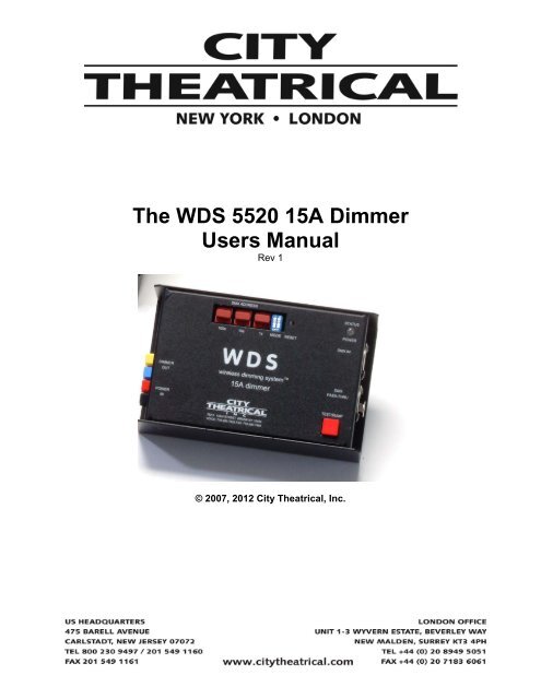
<strong>The</strong> <strong>WDS</strong> <strong>5520</strong> <strong>15A</strong> <strong>Dimmer</strong><br />
<strong>Users</strong> <strong>Manual</strong><br />
Rev 1<br />
© 2007, 2012 <strong>City</strong> <strong>The</strong>atrical, Inc.
CONTENTS<br />
COMPLIANCE INFORMATION .................................................................................................... 3<br />
Safety Notices ........................................................................................................................ 3<br />
Setup and Controls ....................................................................................................................... 4<br />
Connections .................................................................................................................................. 5<br />
Protective Features ....................................................................................................................... 5<br />
Switch Diagnostics ........................................................................................................................ 6<br />
Fuse Replacement ........................................................................................................................ 6<br />
Wire Gauge ................................................................................................................................... 6<br />
Operating Temperature ................................................................................................................. 6<br />
Batteries and Power Considerations ......................................................................................... 7<br />
Unit Specifications ........................................................................................................................ 9<br />
FIGURES<br />
Figure 1, <strong>15A</strong> <strong>Dimmer</strong> Top and Front Panel ................................................................................. 4<br />
Figure 2, <strong>15A</strong> <strong>Dimmer</strong> LED Key .................................................................................................... 4<br />
Figure 3, Mode Switch Selection Chart ......................................................................................... 5<br />
Figure 4, Switch Diagnostics ......................................................................................................... 6<br />
Figure 5, Typical Single 12V Battery System ................................................................................ 7<br />
Figure 6, Typical Continuous Battery Life for 12AH Battery ......................................................... 8<br />
Figure 7, Two Battery 12V (parallel) System ................................................................................ 8<br />
Figure 8, Two Battery 24V (series) System .................................................................................. 9<br />
Page 2
COMPLIANCE INFORMATION<br />
<strong>The</strong> <strong>5520</strong> <strong>Dimmer</strong> is ETL Listed and conforms to UL 508A<br />
<strong>The</strong> <strong>5520</strong> <strong>Dimmer</strong> is CE Certified<br />
Standards Applied:<br />
BS EN 60950-1:2002 incorporating Corrigendum No. 1 and Amendment No. 1<br />
EN <strong>5520</strong>3-1: 1996<br />
EN <strong>5520</strong>3-2: 1996<br />
EN 301 489-1 V1.4.1<br />
EN 301 489-3 V1.4.1<br />
Products Conform to CE Marking Directive 93/68/EEC<br />
All <strong>WDS</strong> models are RoHS compliant<br />
Safety Notices<br />
Please read this entire manual before using your new equipment. Please keep the manual in a<br />
safe place so you can refer to it in the future as required.<br />
<strong>The</strong> <strong>WDS</strong> System is intended for use only by qualified professionals. Connection, installation<br />
and hanging of this equipment must be performed in accordance with all pertinent local, regional<br />
and national safety codes and regulations.<br />
SHoW DMX equipment is intended for indoor use only unless specified for outdoor use.<br />
Keep the equipment dry! Do not operate the equipment if it gets wet!<br />
Do not operate in excessive heat/direct sunlight. Maximum operating temperature 40° C<br />
Be sure installation provides adequate ventilation. Some system components can produce<br />
significant heat and must be properly installed to allow proper cooling and assure user safety<br />
(please see specific notes about 5620 <strong>Dimmer</strong> installation and heat in this manual). All sides of<br />
the equipment must be clear of obstruction and allow free airflow.<br />
Page 3
<strong>The</strong> <strong>15A</strong> <strong>Dimmer</strong> #<strong>5520</strong><br />
TOP VIEW<br />
5 4 3 1<br />
FRONT VIEW<br />
8<br />
9<br />
6<br />
7<br />
2<br />
Figure 1, <strong>15A</strong> <strong>Dimmer</strong> Top and Front Panel<br />
Setup and Controls<br />
1. STATUS/POWER LED: This single Bi-Color LED indicates the status of a number of<br />
things including power, DMX, and output.<br />
<strong>The</strong> LED conditions are as follows:<br />
LED State/Color<br />
Regular blinking Green<br />
Solid Green<br />
Solid Amber<br />
Flashing between Red and Green/Amber<br />
Flashing Red<br />
Figure 2, <strong>15A</strong> <strong>Dimmer</strong> LED Key<br />
Condition<br />
<strong>Dimmer</strong> has power, CPU is running<br />
DMX Present, Output OFF<br />
DMX Present, Output FULL<br />
DMX Lost, <strong>Dimmer</strong> holding Last Level<br />
Low Battery<br />
2. TEST/BUMP Button: Press to test fire load (the LED will turn amber when the button is<br />
pressed.)<br />
3. RESET switch: This switch is recessed to prevent unintentional operation. Press with a<br />
pen or other similar device to reset the <strong>Dimmer</strong>’s internal processors.<br />
Page 4
4. MODE DIP switch: This 2 position DIP switch selects the operation mode as follows<br />
Switch Setting<br />
OFF OFF<br />
ON OFF<br />
OFF ON<br />
ON ON<br />
Function<br />
Normal Dimming, ISL Curve<br />
NON - DIM<br />
Linear Dimming Curve<br />
LED Curve<br />
Figure 3, Mode Switch Selection Chart<br />
5. DMX ADDRESS BCD Rotary Switches: <strong>The</strong>se BCD rotary switches are used to set the<br />
unit’s specific DMX address to any value from 1 to 512.<br />
Connections<br />
6. POWER IN Anderson Power Pole Connector Set: Connect to Battery Power. Red =<br />
+12-24VDC, Black = DC Common.<br />
7. DIMMER OUT Anderson Power Pole Connector Set: Connect to the load to be dimmed.<br />
Yellow = + VDC (0-Full), Blue = DC Common .<br />
8. DMX INPUT, 5P XLR Male: This is a standard DMX 512 input. Connect to the DMX<br />
output port of the Receiver, or any standard DMX output device.<br />
9. DMX PASS-THRU, 5P XLR Female: This pass-thru is provided to allow connection of<br />
downstream DMX devices.<br />
DMX INPUT/PASS-THRU special features:<br />
• <strong>The</strong> DMX INPUT is provided with auto-termination, so no other end-of-line<br />
termination setting is required.<br />
• During normal operation, the <strong>WDS</strong> 15 Amp <strong>Dimmer</strong> re-generates the DMX 512<br />
data presented at the Pass-Thru output, so the output may supply a full<br />
compliment of DMX load.<br />
• If the power supply is removed or other system failure occurs, the DMX input will<br />
automatically be switched over to a hardwired connection to the pass-thru,<br />
assuring continued delivery of the DMX data to downstream devices.<br />
Protective Features<br />
• Low Battery Power: If the connected Battery drops below a preset voltage, the <strong>Dimmer</strong><br />
will shut down, and will not restart until reset (the Low Battery indication will light). This<br />
feature protects rechargeable batteries from discharging to the point where they cannot<br />
be recharged with a standard charger. <strong>The</strong> standard factory set cut-off point is 7VDC.<br />
Other settings are available on a custom basis; please consult <strong>City</strong> <strong>The</strong>atrical.<br />
• Internal Watchdog for DMX processor and <strong>Dimmer</strong> Processor: If the DMX processor<br />
fails, the LED will flash at 1 sec interval (red or amber depending on DMX failure mode)<br />
and the load output will be turned off, protecting the battery and load. If the <strong>Dimmer</strong><br />
processor fails, the load output will be turned off, protecting the battery and load.<br />
• Internal reverse power polarity protection: <strong>The</strong> internal power supply circuitry is<br />
designed to protect the control electronics from damage if the battery leads are<br />
Page 5
accidentally reversed or plugged into the DIMMER OUTPUT connection.<br />
• Hold Last valid DMX Level: If DMX is lost, the <strong>WDS</strong> <strong>15A</strong> <strong>Dimmer</strong> will hold the last valid<br />
level for about 5 minutes, and then fade to black.<br />
Switch Diagnostics<br />
Setting the BCDs to the settings shown below and resetting the unit will start the following<br />
diagnostic self tests:<br />
BCD<br />
Settings<br />
MODE DIP<br />
Settings<br />
Function<br />
Tested<br />
601 Ones (1s) BCD<br />
602 Tens (10s) BCD<br />
603<br />
Hundreds (100s)<br />
BCD<br />
Indication<br />
LED Will flash<br />
= to the number<br />
the “1s” BCD is set to<br />
LED Will flash<br />
= to the number<br />
the “10s” BCD is set to<br />
LED Will flash<br />
= to the number<br />
the “100s” BCD is set to<br />
604 0 0 DIP Switch No LED Flashes<br />
0 1 DIP Switch 1 LED Flash<br />
1 0 DIP Switch 2 LED Flashes<br />
1 1 DIP Switch Fast Red/Green/Amber Flashes<br />
605<br />
<strong>Manual</strong>ly Set<br />
Output Level<br />
Figure 4, Switch Diagnostics<br />
After reset move the tens and ones BCD<br />
switches to manually set the lamp to a % level<br />
<strong>The</strong> BCD test setting must be set (as above) ether before power is applied or reset is<br />
pressed.<br />
Fuse Replacement<br />
<strong>The</strong> <strong>15A</strong> <strong>Dimmer</strong> contains a replaceable ATO <strong>15A</strong> Fuse. Refer to qualified service personnel if<br />
your unit needs a fuse replacement.<br />
Wire Gauge<br />
When installing this unit in a system, <strong>City</strong> <strong>The</strong>atrical recommends 12 gauge wiring between all<br />
line and load devices to minimize voltage drop, otherwise significant damage could result to the<br />
equipment.<br />
Operating Temperature<br />
Maximum ambient operating temperature is 40°C.<br />
Page 6
LOAD<br />
+<br />
WIRELESS DIMMING SYSTEM<br />
<strong>WDS</strong>-<strong>15A</strong><br />
<strong>15A</strong> DIMMER<br />
RECEIVER<br />
WIRELESS DIMMING SYSTEM<br />
RECEIVER<br />
Figure 5, Typical Single 12V Battery System<br />
Batteries and Power Considerations<br />
Rechargeable 12V batteries used with this system may not charge readily with modern chargers<br />
if they are allowed to discharge past ~ 8.5VDC. When allowed to discharge more, the battery<br />
may load the charger too much, causing the charger to shut down 1 to prevent serious damage.<br />
Furthermore, with some loads the current draw will tend to rise as the available voltage drops. If<br />
the battery is allowed to discharge too far under these conditions, the current may exceed the<br />
limits of the system and cause overheating and/or blow the fuse.<br />
For all these reasons, the <strong>WDS</strong> <strong>Dimmer</strong> is designed with a low power sensing system that shuts<br />
down the dimmer if the battery gets below a safe voltage limit (the standard factory setting is<br />
~9VDC; custom units may be configured with a different limit voltage if needed, consult CTI for<br />
details).<br />
<strong>The</strong> <strong>WDS</strong> <strong>15A</strong> <strong>Dimmer</strong> will control a load of up to 15 amps at any voltage within its rated<br />
operating range of 12-24VDC. At 24V the maximum load is 360 watts, while at 12V the<br />
maximum load is 180 watts. Typical, continuous use battery life for the standard 12 Amp/Hour<br />
CTI 12V rechargeable battery (CTI # 5535) is shown on the next table.<br />
1 If this should happen, the charger may be jump-started by connecting the too-low battery in parallel with<br />
a charged battery, starting the charger, and then removing the full battery once the charging has reached<br />
a stable point.<br />
Page 7
Number of<br />
Batteries<br />
Load<br />
Voltage<br />
Battery<br />
Wiring<br />
Total<br />
watts<br />
Load<br />
Typical Battery<br />
Life per charge<br />
Example of<br />
typical load<br />
types<br />
1 12 n/a 150 20~25 minutes 2 x 75W MR 16<br />
lamps<br />
2 24 Series 300 20~25 minutes 24V Lamps<br />
2 12 Parallel 150 40~50 minutes 2 x 75 W MR 16<br />
lamps<br />
Figure 6, Typical Continuous Battery Life for 12AH Battery<br />
For extended 12V operation, 2 (or more) batteries may be connected together in parallel as<br />
suggested in the table above (see Figure 7). For 24V operation, 2 batteries may be connected<br />
in series so that the battery voltages add together (see Figure 8).<br />
LOAD<br />
+<br />
+<br />
WIRELESS DIMMING SYSTEM<br />
<strong>WDS</strong>-<strong>15A</strong><br />
<strong>15A</strong> DIMMER<br />
RECEIVER<br />
WIRELESS DIMMING SYSTEM<br />
RECEIVER<br />
Figure 7, Two Battery 12V (parallel) System<br />
For 24V <strong>Dimmer</strong> operation, it is recommended that the associated <strong>WDS</strong> Receiver be powered<br />
with 12V from only one of the batteries in the series array (see Figure 8).<br />
Page 8
LOAD<br />
+<br />
WIRELESS DIMMING SYSTEM<br />
<strong>WDS</strong>-<strong>15A</strong><br />
<strong>15A</strong> DIMMER<br />
+<br />
WIRELESS DIMMING SYSTEM<br />
RECEIVER<br />
RECEIVER<br />
Figure 8, Two Battery 24V (series) System<br />
Unit Specifications<br />
<strong>15A</strong> <strong>Dimmer</strong> #<strong>5520</strong>:<br />
• Dimensions: 3.25” x 5.25” x 1.687”<br />
• Power: 12-24V DC, 200mA, From Load Battery Power<br />
• DMX 512 Input: Neutrik NC5MBH 5 pin XLR male connector<br />
• DMX 512 Pass-Through: Neutrik NC5FBH 5 pin XLR female connector<br />
• DMX Addressing: any DMX address 1 – 512, configured with (3) standard BCD<br />
switches<br />
• Bump button for load test<br />
• LED Pilot light<br />
• LED Data Present indication<br />
• LED Output indication<br />
• LED Low Power indication<br />
• Internal diagnostics<br />
• Power and Load Connectors: Anderson Power 1327 series<br />
Page 9
• Max output: 24VDC <strong>15A</strong><br />
• Output: PWM Dimming from 00 (Off) to FF (Full)<br />
• Four user-selectable output modes: two dimmer curves (ISL and linear), LED curve, and<br />
non-dim<br />
Page 10