275 Series Beacon Installation Guide - Code 3 Public Safety ...
275 Series Beacon Installation Guide - Code 3 Public Safety ...
275 Series Beacon Installation Guide - Code 3 Public Safety ...

You also want an ePaper? Increase the reach of your titles
YUMPU automatically turns print PDFs into web optimized ePapers that Google loves.
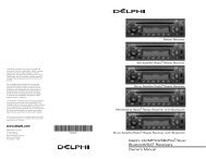
INSTALLATION<br />
& OPERATION<br />
MANUAL<br />
<strong>275</strong>/<strong>275</strong>AH/<strong>275</strong>ASH/<br />
<strong>275</strong>AMH BEACON<br />
<strong>275</strong> <strong>Beacon</strong><br />
12v MODELS<br />
PERMANENT, MAGNETIC MOUNT<br />
BEACONS<br />
Contents:<br />
Introduction ........................................................ 2<br />
Unpacking & Pre-<strong>Installation</strong> .............................. 2<br />
<strong>Installation</strong> & Mounting ....................................... 2<br />
Magnetic Mounting ........................................... 3<br />
Permanent Mounting ........................................ 3<br />
Wiring Instructions ............................................ 5<br />
Maintenance ....................................................... 6<br />
Drill Template............................................................ 7<br />
Warranty ............................................................. 8<br />
IMPORTANT:<br />
Read all instructions and warnings before installing and using.<br />
INSTALLER: This manual must be delivered to the end user of this equipment.
Introduction<br />
The <strong>275</strong> <strong>Beacon</strong> has a sleek, aerodynamtic profile and is a powerful mid-sized, magnetically or permanently<br />
mounted warning device. This product complies with SAE W3-1 97, EMC Directives 95/54/EC and 89/336/EC<br />
!<br />
WARNING!<br />
The use of this or any warning device does not insure that all drivers can or will observe or<br />
react to an emergency warning signal. Never take the right-of-way for granted. It is your<br />
responsibility to be sure you can proceed safely before entering an intersection, driving<br />
against traffic, responding at a high rate of speed, or walking on or around traffic lanes.<br />
The effectiveness of this warning device is highly dependent upon correct mounting and<br />
wiring. Read and follow the manufacturer’s instructions before installing or using this<br />
device. The vehicle operator should insure daily that all features of the device operate<br />
correctly. In use, the vehicle operator should insure the projection of the warning signal is<br />
not blocked by vehicle components (i.e.: open trunks or compartment doors), people,<br />
vehicles, or other obstructions.<br />
This equipment is intended for use by authorized personnel only. It is the user’s responsibility<br />
to understand and obey all laws regarding emergency warning devices. The user<br />
should check all applicable city, state and federal laws and regulations.<br />
<strong>Code</strong> 3, Inc., assumes no liability for any loss resulting from the use of this warning device.<br />
Proper installation is vital to the performance of this warning device and the safe operation<br />
of the emergency vehicle. It is important to recognize that the operator of the emergency<br />
vehicle is under psychological and physiological stress caused by the emergency situation.<br />
The warning device should be installed in such a manner as to: A) Not reduce the output<br />
performance of the system, B) Place the controls within convenient reach of the operator<br />
so that he can operate the system without losing eye contact with the roadway.<br />
Emergency warning devices often require high electrical voltages and/or currents. Properly<br />
protect and use caution around live electrical connections. Grounding or shorting of<br />
electrical connections can cause high current arcing, which can cause personal injury and/<br />
or severe vehicle damage, including fire.<br />
PROPER INSTALLATION COMBINED WITH OPERATOR TRAINING IN THE PROPER<br />
USE OF EMERGENCY WARNING DEVICES IS ESSENTIAL TO INSURE THE SAFETY<br />
OF EMERGENCY PERSONNEL AND THE PUBLIC.<br />
Unpacking & Pre-installation<br />
Carefully remove the beacon and place it on a flat surface, taking care not to scratch the lens. Examine the<br />
unit for transit damage, broken lamps, etc.<br />
If it is convenient, you may wish to test the unit before installation. To test, touch the black wire to the<br />
negative ground (earth) and the red wire to the +12 Volts D.C. A battery may be used for this purpose. If the<br />
vehicle has an electrical system other than 12 Volts D.C. negative ground (earth), and you have not ordered a<br />
specially wired beacon, contact your local representative or call the factory for instructions.<br />
<strong>Installation</strong> & Mounting<br />
The <strong>275</strong> <strong>Beacon</strong> may be mounted magnetically or permanently on the roof of the vehicle, or other mounting<br />
surface.<br />
Overall Size : 5.938 Dia. X 5.775 Tall. Magnetic Mount Models.<br />
6.125 Dia. X 6.125 Tall.<br />
General<br />
All devices should be mounted in accordance with the manufacturer's instructions and securely fastened to<br />
vehicle elements of sufficient strength to withstand the forces applied to the device. Driver and/or passenger<br />
air bags (SRS) will affect the way equipment should be mounted. This device should be mounted by permanent<br />
installation and within the zones specified by the vehicle manufacturer, if any. Any device mounted in the<br />
deployment area of an air bag will damage or reduce the effectiveness of the air bag and may damage or<br />
dislodge the device. Installer must be sure that this device, its mounting hardware and electrical supply wiring<br />
does not interfere with the air bag or the SRS wiring or sensors. Front or rear grille/bumper placement must<br />
avoid interference with SRS sensors. Mounting the unit inside the vehicle by a method other than permanent<br />
installation is not recommended as unit may become dislodged during swerving, sudden braking or collision.<br />
Failure to follow instructions can result in personal injury.<br />
2
Magnetic Mounting<br />
!<br />
WARNING!<br />
1) Rust Stains: The magnetic mount is not intended as a permanent mounting for the<br />
beacon. Long duration usage of any magnet will expose the high iron content of the steel<br />
causing rust. The device should be removed when not used to prevent rust stains. Metallic<br />
debris collected by the magnet will also contribute to rust stains. Insure that the magnet<br />
is kept clean.<br />
2) Surface rust stains can usually be removed with chrome polish, available at most auto<br />
part stores.<br />
3) As with any magnetically-mounted warning device, its use on the exterior of a moving<br />
vehicle is at the sole discretion and responsibility of the user.<br />
This magnetic mount product provides a secure, temporary installation in most circumstances<br />
and is recommended for stationary use only. For maximum warning signal, mount<br />
the beacon on the highest possible flat, level surface of the vehicle.<br />
The <strong>275</strong> Magnetic Based <strong>Beacon</strong> provides a secure, temporary installation in most circumstances. The<br />
beacon should be placed in the center of the roof where the least amount of curvature occurs. The<br />
beacon should not be used on a vinyl covered roof. Before installing, check the magnet for clinging<br />
debris. Any foreign matter can reduce holding power and scratch your vehicle's paint. The roof surface<br />
should be dry and have a dull, not glossy finish. A glossy, highly waxed finish will reduce the friction; and<br />
the magnet, though quite powerful, will have a greatly reduced effect. Place and remove your beacon<br />
without sliding to avoid scratching. When removing, lift one edge straight up without sliding. The suction/<br />
magnetic mount has a tab to release the suction, refer to Figure 1.<br />
When the beacon is placed on the roof, it should adhere firmly to the surface. If the unit slides or moves<br />
easily, a proper installation has not been obtained, most probably for one of the reasons mentioned above.<br />
In this situation, the user should not attempt to drive with the beacon in place. If the user has attempted<br />
to obtain a good installation and still has questions, we recommend that the user (customer) contact his/<br />
her distributor or the factory.<br />
Do not install the beacon closer than 20" to any antenna or aerial.<br />
FIGURE 1<br />
LIFT UP TO RELEASE<br />
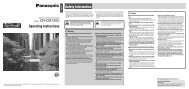
Permanent Mounting<br />
The <strong>275</strong> Permanent Mount <strong>Beacon</strong> provides a secure, permanent installation. To begin installation,<br />
consider where the wire routing will be located. Electrical cables can affect other equipment! Route product<br />
supply cables away from sensitive cables (e.g. radio, aerials and anti-lock braking systems etc.) If this is<br />
not possible, cross the cables at 90 Deg. Using the enclosed template, refer to Figure 5 on page 7, mark<br />
the centers for mounting holes on the vehicle roof or mounting surface. Drills can be dangerous! Make<br />
sure the person operating the drill is trained and takes adequate safety precautions. Drill a .250" hole<br />
through all 3 centers, a .500" hole at the center and remove any burrs. Place the supplied mounting<br />
gasket in position, refer to Figure 2. Run, the supplied M6 machine screws through the drilled holes (For<br />
thicker surfaces use longer screws). Place one nut, with lock washer, onto each screw and tighten screws<br />
until base is properly secured to mounting surface. Number 8 self-tapping sheet metal screws (user<br />
supplied) may be substituted for the bolts and threaded into the bosses molded in the base.<br />
3
DRAIN SLOT TOWARD REAR OF VEHICLE<br />
SUPPLIED MOUNTING GASKET<br />
LIGHT BASE<br />
BOLT M6<br />
VEHICLE PANEL<br />
TIGHTENING TORQUE: 5 lb-in<br />
SPRING WASHER<br />
NUT M6<br />
18-16 GA WIRE<br />
(WIRE NOT SUPPLIED)<br />
.250in FEMALE<br />
CONNECTOR (+)<br />
.187in FEMALE<br />
CONNECTOR (-)<br />
FIGURE 2<br />
4
Wiring Instructions<br />
!<br />
WARNING!<br />
Larger wires and tight connections will provide longer service life for components. For high<br />
current wires it is highly recommended that terminal blocks or soldered connections be<br />
used with shrink tubing to protect the connections. Do not use insulation displacement<br />
connectors (e.g. 3M ® Scotchlock type connectors). Route wiring using grommets and<br />
sealant when passing through compartment walls. Minimize the number of splices to<br />
reduce voltage drop. High ambient temperatures (e.g. under-hood) will significantly reduce<br />
the current carrying capacity of wires, fuses, and circuit breakers. Use "SXL" type wire in<br />
engine compartment. All wiring should conform to the minimum wire size and other<br />
recommendations of the manufacturer and be protected from moving parts and hot<br />
surfaces. Looms, grommets, cable ties, and similar installation hardware should be used to<br />
anchor and protect all wiring.<br />
Fuses or circuit breakers should be located as close to the power takeoff points as possible<br />
and properly sized to protect the wiring and devices.<br />
Particular attention should be paid to the location and method of making electrical<br />
connections and splices to protect these points from corrosion and loss of conductivity.<br />
Ground terminations should only be made to substantial chassis components, preferably<br />
directly to the vehicle battery.<br />
The user should install a fuse sized to approximately 125% of the maximum Amp capacity<br />
in the supply line to protect against short circuits. For example, a 30 Amp fuse should<br />
carry a maximum of 24 Amps. DO NOT USE 1/4" DIAMETER GLASS FUSES AS THEY<br />
ARE NOT SUITABLE FOR CONTINUOUS DUTY IN SIZES ABOVE 15 AMPS. Circuit<br />
breakers are very sensitive to high temperatures and will "false trip" when mounted in hot<br />
environments or operated close to their capacity.<br />
<strong>275</strong> Magnetic Mount <strong>Beacon</strong> - The <strong>275</strong> <strong>Beacon</strong> can be equipped with a cord that plugs into a 12 Volt<br />
D.C. cigarette lighter; rotate and push with reasonable moderate force which insures the best possible<br />
connection.<br />
<strong>275</strong> Permanent Mount <strong>Beacon</strong> - The <strong>275</strong> beacon is designed to operate on a 12 Volt D.C. negative<br />
ground (earth) system. Use #18 GA. or larger wires. Connect black lead to vehicle chassis (earth),<br />
or preferably the negative (earth) terminal of the battery. Bring the red lead to the user supplied<br />
control switch, and then to the battery or to the stud on the battery side of the starter solenoid or<br />
alternator. Install a fuse or circuit breaker of 8 Amp capacity in the supply line to protect the vehicle's<br />
wiring system against short circuits.<br />
LENS P/N<br />
T07982<br />
T07983<br />
T07984<br />
COLOR<br />
RED<br />
BLUE<br />
AMBER<br />
ANTI-THEFT SCREW<br />
LENS OPENING AND CLOSING<br />
5
WARNING: RATED VOLTAGE IS INDICATED ON THE BACK OF REFLECTOR<br />
BULB P/N<br />
T01543<br />
12v APPLICATIONS ONLY<br />
DO NOT TOUCH GLASS PORTION<br />
OF LAMP<br />
FIGURE 4<br />
Maintenance<br />
Do not oil or grease this unit. It is constructed with permanently lubricated bearings which do not need<br />
lubrication. Keep the unit clean by disassembling it and clearing any debris or dirt. Clean lens and base<br />
with mild soap and water, or CODE 3 ® lens polish using a soft cloth. The lens may be removed, and the<br />
lamps replaced as shown in Figure 4. Use only lamps with the same rated wattage and voltage.<br />
!<br />
WARNING!<br />
Use no SOLVENTS on lens.<br />
Lamps are extremely hot! Allow to cool completely before attempting to remove. Gloves<br />
and eye protection should be worn when handling halogen lamps as they are pressurized and<br />
accidental breakage can result in flying glass.<br />
Failure to follow above warnings or installation and user instructions can result in loss of warranty coverage.<br />
6
Drill Template<br />
5.125<br />
120.0°<br />
120.0°<br />
3X .250<br />
.400<br />
FIGURE 5<br />
NOT TO SCALE<br />
7
WARRANTY<br />
<strong>Code</strong> 3, Inc.'s emergency devices are tested and found to be operational at the time of<br />
manufacture. Provided they are installed and operated in accordance with manufacturer's<br />
recommendations, <strong>Code</strong> 3, Inc. guarantees all parts and components except the lamps to a period<br />
of 1 year (unless otherwise expressed) from the date of purchase or delivery, whichever is later.<br />
Units demonstrated to be defective within the warranty period will be repaired or replaced at the<br />
factory service center at no cost.<br />
Use of lamp or other electrical load of a wattage higher than installed or recommended by<br />
the factory, or use of inappropriate or inadequate wiring or circuit protection causes this warranty<br />
to become void. Failure or destruction of the product resulting from abuse or unusual use and/<br />
or accidents is not covered by this warranty. <strong>Code</strong> 3, Inc. shall in no way be liable for other<br />
damages including consequential, indirect or special damages whether loss is due to negligence<br />
or breach of warranty.<br />
CODE 3, INC. MAKES NO OTHER EXPRESS OR IMPLIED WARRANTY INCLUD-<br />
ING, WITHOUT LIMITATION, WARRANTIES OF FITNESS OR MERCHANTABILITY,<br />
WITH RESPECT TO THIS PRODUCT.<br />
PRODUCT RETURNS<br />
If a product must be returned for repair or replacement*, please contact our factory to<br />
obtain a Return Goods Authorization Number (RGA number) before you ship the product to<br />
<strong>Code</strong> 3, Inc. Write the RGA number clearly on the package near the mailing label. Be sure you<br />
use sufficient packing materials to avoid damage to the product being returned while in transit.<br />
*<strong>Code</strong> 3, Inc. reserves the right to repair or replace at its discretion. <strong>Code</strong> 3, Inc. assumes no responsibility or liability for expenses incurred<br />
for the removal and /or reinstallation of products requiring service and/or repair.; nor for the packaging, handling, and shipping: nor for the handling of<br />
products return to sender after the service has been rendered.<br />
<strong>Public</strong> <strong>Safety</strong> Equipment, Inc.<br />
10986 N. Warson Road<br />
St. Louis, Missouri 63114-2029—USA<br />
Ph. (314) 426-2700 Fax (314) 426-1337<br />
www.code3pse.com<br />
<strong>Code</strong> 3 is a registered trademarks of<br />
<strong>Public</strong> <strong>Safety</strong> Equipment, Inc.<br />
<strong>Code</strong> 3, ® Inc., a subsidiary of<br />
<strong>Public</strong> <strong>Safety</strong> Equipment, Inc.<br />
Revision 1 5/03 - Instruction Book Part No. T07948<br />
©2002 <strong>Public</strong> <strong>Safety</strong> Equipment, Inc. Printed in USA