PM4H-W - analog timer - twin - Panasonic Electric Works Europe AG
PM4H-W - analog timer - twin - Panasonic Electric Works Europe AG
PM4H-W - analog timer - twin - Panasonic Electric Works Europe AG

You also want an ePaper? Increase the reach of your titles
YUMPU automatically turns print PDFs into web optimized ePapers that Google loves.
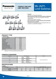
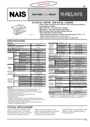
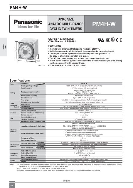
<strong>PM4H</strong>-W<br />
DIN48 SIZE<br />
ANALOG MULTI-RANGE<br />
CYCLIC TWIN TIMERS<br />
<strong>PM4H</strong>-W<br />
UL File No.: E122222<br />
CSA File No.: LR39291<br />
Analog<br />
Timers<br />
48<br />
1.890<br />
48<br />
1.890<br />
62.5<br />
2.461<br />
mm inch<br />
Features<br />
• A single <strong>twin</strong> <strong>timer</strong> unit that repeats (variable) ON/OFF.<br />
• Multiple ranges with a 0.1 s to 500 h time specification on a single unit.<br />
• The output ON/OFF operation is indicated by red and green LED’s.<br />
It’s easy to check the operation at a glance.<br />
• The AC free power supply and shorter body make it easier to use.<br />
• A new screw terminal type has been added to the conventional pin type. Wiring<br />
can be done easily with a screwdriver.<br />
• Compliant with UL, CSA, CE and LLOYD.<br />
Specifications<br />
Item<br />
Rating<br />
Time<br />
accuracy<br />
Note:1)<br />
Contact<br />
Life<br />
<strong>Electric</strong>al<br />
function<br />
Mechanical<br />
function<br />
Operating<br />
condition<br />
Others<br />
Rated operating voltage<br />
Rated frequency<br />
Rated power consumption<br />
Rated control capacity<br />
Operation mode<br />
Time range<br />
Operation time fluctuation<br />
Setting error<br />
Voltage error<br />
Temperature error<br />
Contact arrangement<br />
Type<br />
Contact resistance (Initial value)<br />
Contact material<br />
Mechanical (contact)<br />
<strong>Electric</strong>al (contact)<br />
Allowable operating voltage range<br />
Insulation resistance (Initial value)<br />
Breakdown voltage (Initial value)<br />
Min. power off time<br />
Max. temperature rise<br />
Functional<br />
Vibration resistance<br />
Destructive<br />
Functional<br />
Shock resistance<br />
Destructive<br />
Ambient temperature<br />
Ambient humidity<br />
Atmospheric pressure<br />
Ripple factor (DC type)<br />
Protective construction<br />
Weight<br />
<strong>PM4H</strong>-W<br />
100 to 240V AC, 48 to 125V DC, 12V DC, 24V AC/DC<br />
50/60Hz common (AC operating type)<br />
Approx. 10VA (100 to 240V AC)<br />
Approx. 2.5VA (24V AC)<br />
Approx. 1.5W (12V DC, 24V DC, 48 to 125V DC)<br />
5A 250V AC (resistive load)<br />
Cyclic (OFF-start/Twin operation)<br />
1s to 500h 16 time ranges switchable (T1, T2 time setting individually)<br />
0.3% (power off time change at the range of 0.3s to 1h)<br />
5% (Full-scale value)<br />
0.5% (at the operating voltage changes between 85 to 110%)<br />
2% (at 20C ambient temp. at the range of –10 to +50C +14 to 122F)<br />
Timed-out 2 Form C<br />
Max. 100m (at 1A 6V DC)<br />
Silver alloy<br />
210 7<br />
10 5 (at rated control capacity)<br />
85 to 110% of rated operating voltage (at 20C coil temp.)<br />
Between live and dead metal parts<br />
Between input and output<br />
Min. 100M<br />
(At 500V DC)<br />
Between contacts of different poles<br />
Between contacts of same pole<br />
2,000Vrms for 1 min Between live and metal parts<br />
2,000Vrms for 1 min Between input and output<br />
2,000Vrms for 1 min Between contacts of different poles<br />
1,000Vrms for 1 min Between contacts of same pole<br />
300ms<br />
55C 131F<br />
10 to 55Hz: 1 cycle/min double amplitude of 0.25mm (10min on 3 axes)<br />
10 to 55Hz: 1 cycle/min double amplitude of 0.375mm (1h on 3 axes)<br />
Min. 98m/s 2 (4 times on 3 axes)<br />
Min. 980m/s 2 (5 times on 3 axes)<br />
–10 to +50C +14 to +122F<br />
30 to 85%RH (non-condensing)<br />
860 to 1,060hPa<br />
20%<br />
IP65 on front panel (using rubber gasket ATC18002) <br />
120g 4.233 oz (Pin type), 130g 4.586 oz (Screw terminal type)<br />
Notes:<br />
1) Unless otherwise specified, the measurement conditions at the maximum scale time standard are specified to be the rated operating voltage (within 5% ripple<br />
factor for DC), 20°C 68°F ambient temperature, and 1s power off time.<br />
2) For the 1s range, the tolerance for each specification becomes ±10ms.<br />
3) As internal components may become worn when using continuous conduction, the product should be replaced periodically.<br />
09/2009<br />
50
<strong>PM4H</strong>-W<br />
Time range<br />
All types of <strong>PM4H</strong>-W <strong>timer</strong> have multi-time range.<br />
16 time ranges are selectable.<br />
1s to 500h (Max. range) is controlled.<br />
Time unit<br />
Scale<br />
sec min hrs 10h<br />
1<br />
0.1s to 1s 0.1 min to 1 min 0.1h to 1h 1.0h to 10h<br />
5 Control 0.5s to 5s 0.5 min to 5 min 0.5h to 5h 5h to 50h<br />
10 time range 1.0s to 10s 1.0 min to 10 min 1.0h to 10h 10h to 100h<br />
50 5s to 50s 5 min to 50 min 5h to 50h 50h to 500h<br />
Product types<br />
Operating<br />
Protective Rated Operating Terminal<br />
Type Contact arrangement Time range Part number<br />
mode<br />
structure voltage<br />
type<br />
<strong>PM4H</strong>-W<br />
Twin <strong>timer</strong><br />
Cyclic<br />
(OFF-start,<br />
Twin)<br />
Relay<br />
Timed-out<br />
2 Form C<br />
16 selectable ranges<br />
(1s to 500h)<br />
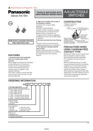
Terminal layouts and wiring diagrams<br />
Pin Type<br />
Cyclic timed-out relay contact: 2C<br />
Screw terminal type<br />
Cyclic timed-out relay contact: 2C<br />
IP65<br />
IP50<br />
100 to 240V AC<br />
48 to 125V DC<br />
24V AC/DC<br />
12V DC<br />
100 to 240V AC<br />
48 to 125V DC<br />
24V AC/DC<br />
12V DC<br />
8 pins<br />
Screw terminal<br />
8 pins<br />
Screw terminal<br />
8 pins<br />
Screw terminal<br />
8 pins<br />
Screw terminal<br />
8 pins<br />
Screw terminal<br />
8 pins<br />
Screw terminal<br />
8 pins<br />
Screw terminal<br />
8 pins<br />
Screw terminal<br />
<strong>PM4H</strong>W-H-AC240VW<br />
<strong>PM4H</strong>W-H-AC240VSW<br />
<strong>PM4H</strong>W-H-DC125VW<br />
<strong>PM4H</strong>W-H-DC125VSW<br />
<strong>PM4H</strong>W-H-24VW<br />
<strong>PM4H</strong>W-H-24VSW<br />
<strong>PM4H</strong>W-H-DC12VW<br />
<strong>PM4H</strong>W-H-DC12VSW<br />
<strong>PM4H</strong>W-H-AC240V<br />
<strong>PM4H</strong>W-H-AC240VS<br />
<strong>PM4H</strong>W-H-DC125V<br />
<strong>PM4H</strong>W-H-DC125VS<br />
<strong>PM4H</strong>W-H-24V<br />
<strong>PM4H</strong>W-H-24VS<br />
<strong>PM4H</strong>W-H-DC12V<br />
<strong>PM4H</strong>W-H-DC12VS<br />
Analog<br />
Timers<br />
N.O.<br />
N.C.<br />
N.C.<br />
N.O.<br />
5<br />
3 4 N.C. N.O. 6 7 8 9 10 N.C. N.O.<br />
11<br />
6<br />
1 2 3 4 5<br />
2 7<br />
1 8<br />
Operating<br />
Operating voltage<br />
(–) (+)<br />
(+) voltage (–)<br />
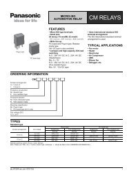
Dimensions<br />
• Screw terminal type: M3.5<br />
• Pin type<br />
mm inch<br />
Toletance: 0.5 .020<br />
48<br />
1.890<br />
6.0<br />
17.0 .236<br />
.670<br />
62.5<br />
2.461<br />
48<br />
1.890<br />
6.0<br />
17.0 .236<br />
.670<br />
66.5<br />
2.618 14.5<br />
.571<br />
48<br />
1.890<br />
41<br />
1.614<br />
44.5<br />
1.752<br />
48<br />
1.890<br />
41<br />
1.614<br />
44.5<br />
1.752<br />
Operation<br />
Power supply<br />
T1<br />
T2<br />
T1<br />
Time-delay contact<br />
(N.O. contact)<br />
Time-delay contact<br />
(N.C. contact)<br />
Output ON-OFF<br />
indicator<br />
: Output OFF indicator (green)<br />
: Output ON indicator (orange)<br />
T1: OFF set time<br />
T2: ON set time<br />
09/2009<br />
51
<strong>PM4H</strong> SERIES MODES AND TIME SETTING<br />
Analog<br />
Timers<br />
1. Operation method<br />
1) Operation mode setting<br />
[<strong>PM4H</strong>-A type]<br />
8 operation modes are selectable with<br />
operation mode selector.<br />
Turn the operation mode selector with<br />
screw driver.<br />
Operation mode is shown up through the<br />
window above the mode selector. The<br />
marks are ON , FL , FO , OF1 , SF , OS , OF2 , OC .<br />
Turn the mode selector to the mark until<br />
you can check by clicking sound.<br />
Confirm the mode selector position if it is<br />
correct.<br />
If the position is not stable, the <strong>timer</strong><br />
might mis-operate.<br />
2) Time range setting<br />
[<strong>PM4H</strong> series common]<br />
16 time ranges are selectable between<br />
1s to 500h.<br />
Turn the time range selector with the<br />
screw driver.<br />
Clockwise turning increases the time<br />
range, and Counter-clockwise turning<br />
decrease the time range.<br />
Confirm the range selector position if it is<br />
correct.<br />
If the position is not stable, the <strong>timer</strong><br />
might mis-operate.<br />
3) Time setting [common]<br />
To set the time, turn the set dial to a<br />
desired time within the range.<br />
Instantaneous output will be on when the<br />
dial is set to “0”.<br />
When the instantaneous output is used,<br />
the dial should be set under “0” range.<br />
(Instantaneous output area)<br />
When power supply is on, the time<br />
range, setting time and operation mode<br />
cannot be changed.<br />
Turn off the power supply or a reset signal<br />
is applied to set the new operation<br />
mode.<br />
If the position is not stable, the <strong>timer</strong><br />
might mis-operate.<br />
2. How to use “Set ring” [<strong>PM4H</strong> series common]<br />
1) Fixed time setting<br />
2) Time range setting<br />
Set the desired time and put 2 set rings Example: Time range 20s to 30s.<br />
together.<br />
Shorter time value setting<br />
Insert the rings into stopper to fix the<br />
Set the dial to 20s.<br />
time.<br />
Place the stop ring at the right side of<br />
Stopper boss<br />
stopper.<br />
Stopper<br />
Longer time value setting<br />
Set the dial to 30s.<br />
Place the stop ring at the left side of<br />
stopper.<br />
Set range<br />
Shorter time value<br />
Stopper boss<br />
Longer time value<br />
Set ring (2 pcs)<br />
ATC18001 (sold separately)<br />
Set dial<br />
20<br />
Stop ring<br />
30<br />
0 0<br />
SEC<br />
SEC<br />
Note) The stoppers for the lower limit setting set ring and the upper limit setting set ring face the opposite directions.<br />
Applicable standard (<strong>PM4H</strong> series common)<br />
Safety standard EN61812-1 Pollution Degree 2/Overvoltage Category III<br />
EMC<br />
(EMI)EN61000-6-4<br />
Radiation interference electric field strength<br />
Noise terminal voltage<br />
(EMS)EN61000-6-2<br />
Static discharge immunity<br />
RF electromagnetic field immunity<br />
EFT/B immunity<br />
Surge immunity<br />
Conductivity noise immunity<br />
Power frequency magnetic field immunity<br />
Voltage dip/Instantaneous stop/Voltage fluctuation immunity<br />
EN55011 Group1 ClassA<br />
EN55011 Group1 ClassA<br />
EN61000-4-2 4 kV contact<br />
8 kV air<br />
EN61000-4-3 10 V/m AM modulation (80 MHz to 1 GHz)<br />
10 V/m pulse modulation (895 MHz to 905 MHz)<br />
EN61000-4-4 2 kV (power supply line)<br />
1 kV (signal line)<br />
EN61000-4-5 1 kV (power line)<br />
EN61000-4-6 10 V/m AM modulation (0.15 MHz to 80 MHz)<br />
EN61000-4-8 30 A/m (50 Hz)<br />
EN61000-4-11 10 ms, 30% (rated voltage)<br />
100 ms, 60% (rated voltage)<br />
1,000 ms, 60% (rated voltage)<br />
5,000 ms, 95% (rated voltage)<br />
52<br />
09/2009
PRECAUTIONS IN USING THE <strong>PM4H</strong> SERIES<br />
1. Input connections (<strong>PM4H</strong>-A type)<br />
1) Be sure not to use terminal as the<br />
common terminal of the input signal as<br />
shown in Fig. A. Otherwise, the internal<br />
circuit of the <strong>timer</strong> may be damaged. Use<br />
terminal as the common terminal as<br />
shown in Fig. B.<br />
No good<br />
Operating<br />
voltage<br />
Good<br />
Operating<br />
voltage<br />
If the circuits is connected as in Fig. C,<br />
the internal circuits must be broken. Be<br />
sure to connect the circuit as in Fig. D.<br />
Good<br />
Fig. C<br />
No good<br />
Fig. D<br />
2) When one input signal is simultaneously<br />
applied to more than one <strong>timer</strong>,<br />
be sure to avoid the wiring shown in Fig.<br />
E. Otherwise, the short-circuit current<br />
will flow and cause damage. Be sure to<br />
align the polarity of the power supply as<br />
shown in Fig. F.<br />
Good<br />
Fig. E<br />
No good<br />
Fig. A<br />
Fig. B<br />
5<br />
5<br />
Fig. F<br />
Contact or<br />
non-contact input<br />
2<br />
2<br />
2<br />
2<br />
6<br />
7<br />
2 10<br />
6<br />
7<br />
2 10<br />
6<br />
6<br />
T<br />
T<br />
Input<br />
terminal<br />
10<br />
Input<br />
terminal<br />
10<br />
Input<br />
terminal<br />
10<br />
Input<br />
terminal<br />
10<br />
10<br />
2<br />
10<br />
2<br />
Contact input<br />
(or non-contact<br />
input)<br />
Contact input<br />
(or non-contact<br />
input)<br />
Power<br />
supply<br />
Power<br />
supply<br />
3) Terminal - (screw terminal x-c)<br />
should be connected as the start input.<br />
Connect terminals - (screw terminal<br />
x-v) for reset signal input. Connect<br />
terminals - (screw terminal x-b) for<br />
stop signal input. Be sure not to connect<br />
with other terminals and apply excessive<br />
voltage. The internal circuit will be damaged.<br />
4) The input wiring other than the power<br />
supply circuit should avoid these conditions,<br />
high-voltage wiring and parallel<br />
wiring with power wire. Wire in short with<br />
using the shielding wire or metal wiring<br />
tube.<br />
5) For start, reset and stop input, use<br />
gold-plated contact with high reliability.<br />
Since contact bouncing causes errors<br />
in the start, use an input contact less<br />
bounce time.<br />
6) Keep the minimum signal input time<br />
over 0.05 s.<br />
2. Input signal conditions<br />
(<strong>PM4H</strong>-A type)<br />
1) Connection of contact input (Pin type<br />
example<br />
Reset input<br />
Start input<br />
Stop input<br />
6<br />
5 7<br />
Use gold-plated contacts with high-reliability.<br />
The bounce time at the contacts<br />
causes errors in the <strong>timer</strong> operation<br />
time. Accordingly, use start input contact<br />
whose bounce time is short. The resistance<br />
when shorted should be less than<br />
1k, and when open resistance should<br />
be more than 100k.<br />
For the screw terminal type, connect the<br />
terminal x to the each input signal.<br />
2) Connection of non-contact input (Pin<br />
type example)<br />
(open-collector)<br />
Reset input<br />
Start input<br />
Stop input<br />
Apply the open-collector connection.<br />
The characteristics of the transistor used<br />
must be VCEO=10V or more, IC=10mA or<br />
more, and ICBO=6μA or less. Additionally,<br />
the input impedance must be 1k or<br />
less, and the residual voltage must be<br />
0.6V or less.<br />
For the screw terminal type, connect the<br />
terminal x to the each input signal.<br />
2<br />
6<br />
5 7<br />
2<br />
3) Connection of non-contact input (Pin<br />
type example)<br />
(voltage input)<br />
Internal circuit<br />
with photoelectric<br />
sensor, etc.<br />
Q<br />
1mA (The start input<br />
is turned on.)<br />
6<br />
5 7<br />
[Example of<br />
start input]<br />
Even if the open collector is not used,<br />
input is also possible from the non-contact<br />
circuit of 6 to 30V DC. In this case,<br />
the start input is turned on when the signal<br />
is turned from H to L.<br />
The residual voltage must be 0.6V or<br />
less when Q is on. On the AC type, an<br />
insulated transformer is required as<br />
the power supply for the photoelectric<br />
sensor, etc. (power supply for the input<br />
devices).<br />
Note: Keep the minimum input signal time of<br />
each signal to 0.05s or more.<br />
3. Checking the contacts before use<br />
(<strong>PM4H</strong>-F only)<br />
When the power ON time is less than<br />
the minimum power application time,<br />
the contacts may remain in an ON state,<br />
so the state of the contacts should be<br />
checked before use. When the contacts<br />
are in an ON state, activating them once<br />
will return them to their normal state (the<br />
OFF state after time-out). (Be aware that<br />
relay characteristics may result in the<br />
contacts being in that same ON state<br />
if exposed to excessive vibration and<br />
impact during transport.)<br />
4. Time setting<br />
To set the time, turn the set dial to a<br />
desired time within the range.<br />
Instantaneous output will be on when the<br />
dial is set to “0”.<br />
When the instantaneous output is used,<br />
the dial should be set under “0” range.<br />
(Instantaneous output area)<br />
Note) When power supply is on, the time<br />
range, setting time and operation mode<br />
cannot be changed.<br />
Turn off the power supply or a reset signal<br />
is applied to set the new operation<br />
mode.<br />
If the position is not stable, the <strong>timer</strong><br />
might mis-operate.<br />
2<br />
Analog<br />
Timers<br />
09/2009<br />
53
PRECAUTIONS IN USING THE <strong>PM4H</strong> SERIES<br />
Analog<br />
Timers<br />
5. Superimposed surge of power<br />
supply (<strong>PM4H</strong> series common)<br />
For the superimposed surge of power<br />
supply, the standard waveform is taken<br />
as the standard value for surge-proof<br />
voltage.<br />
If external surge occurs exceeding the<br />
specified value, the internal circuit may<br />
break down. In this case, use a surge<br />
Operation voltage<br />
100 to 240V AC<br />
100 to 120V AC<br />
200 to 240V AC<br />
48 to 125V DC<br />
12V DC, 24V DC<br />
24V AC/DC<br />
Surge voltage<br />
4,000V<br />
500V<br />
absorption element.<br />
The positive and negative voltages are<br />
applied each five times between the<br />
power pins.<br />
The typical surge absorption elements<br />
include a varistor, a capacitor, and a<br />
diode. If a surge absorption element is<br />
used, use an oscilloscope to see whether<br />
or not the foreign surge exceeding the<br />
specified value appears.<br />
6. Acquisition of CE marking<br />
Please abide by the conditions below<br />
when using in applications that comply<br />
with EN61812-1.<br />
1) Overvoltage category III, pollution<br />
level 2<br />
2) This <strong>timer</strong> employs a power supply<br />
without a transformer, so the power and<br />
input signal terminals are not insulated.<br />
(<strong>PM4H</strong>-A only)<br />
(1) When a sensor is connected to the<br />
input circuit, install double insulation on<br />
the sensor side.<br />
(2) In the case of contact input, use dualinsulated<br />
relays, etc.<br />
3) The load connected to the output contact<br />
should have basic insulation.<br />
This <strong>timer</strong> is protected with basic insulation<br />
and can be double-insulated to meet<br />
EN/IEC requirements by using basic<br />
insulation on the load.<br />
4) Please use a power supply that is<br />
protected by an overcurrent protection<br />
device which complies with the EN/IEC<br />
standard (example: 250 V 1 A fuse, etc.).<br />
5) You must use a terminal socket or<br />
socket for the installation. Do not touch<br />
the terminals or other parts of the <strong>timer</strong><br />
when it is powered. When installing or<br />
un-installing, make sure that no voltage<br />
is being applied to any of the terminals.<br />
6) Do not use this <strong>timer</strong> as a safety circuit.<br />
For example when using a <strong>timer</strong> in<br />
a heater circuit, etc., provide a protection<br />
circuit on the machine side.<br />
09/2009<br />
54