T A B L E O F C O N T E N T S - Panasonic Electric Works Europe AG
T A B L E O F C O N T E N T S - Panasonic Electric Works Europe AG
T A B L E O F C O N T E N T S - Panasonic Electric Works Europe AG

You also want an ePaper? Increase the reach of your titles
YUMPU automatically turns print PDFs into web optimized ePapers that Google loves.
T A B L E O F C O N T E N T S<br />
Page<br />
SELECTOR CHART .......................................................2<br />
TECHNICAL TERMINOLOGY & CAUTIONS<br />
FOR USE.....................................................................4<br />
NS Series ........................................................................7<br />
ND Series mounting hole 16 dia. type...........................20<br />
ND Series mounting hole 22 dia. type...........................41<br />
TURQUOISE SNAP SWITCHES (AJN1/2)...................61<br />
AJ1 (J1)/AJ2 (J2) TOGGLE AND ROCKER<br />
SWITCHES................................................................71<br />
AJ4 (J4) TOGGLE SWITCHES.....................................91<br />
T-15 SERIES SWITCHES Toggle type.........................97<br />
T-15 SERIES SWITCHES Rocker type ........................97<br />
T-15 SERIES SWITCHES Push-button type ................97<br />
T-10 SERIES SWITCHES...........................................114<br />
T-06/T-03 SERIES SWITCHES ..................................117<br />
TUMBLER/ROCKER SWITCHES (WD2/WD3) ..........120<br />
AB2 TYPE PUSH-BUTTON SWITCHES ....................123<br />
ACE PUSH-BUTTON SWITCHES (AB5)....................126<br />
AJ8 SWITCHES<br />
WITH TRIP FUNCTION UPGRADED TYPE ...........128<br />
AJ7 (J7) SWITCHES...................................................133<br />
AJ8 (J8) SWITCHES...................................................141<br />
AJ9 (J9) SWITCHES...................................................147<br />
STANDARDS CHART.................................................153<br />
CE MARKINGS OVERVIEW.......................................154<br />
ISO14001 and ISO9001 Certificate of approval..........155<br />
05/2009<br />
1
SELECTOR CHART<br />
SELECTOR CHART<br />
Selection item<br />
Load<br />
Mounting method<br />
Protect construction<br />
Standard<br />
• Medium-to<br />
high-capacity loads<br />
• Mounting panel<br />
with round holes<br />
• Sealed<br />
construction<br />
• International<br />
standards<br />
dia.<br />
S<br />
Symbol<br />
Enter maximum rated capacity<br />
in table below.<br />
• Snap-in mounting into vertical horizontal<br />
panel with square holes<br />
(Please refer to each catalog<br />
for details about seal grades.)<br />
UL (C-UL), CSA, VDE, TÜV, etc.<br />
• Low-level circuit load<br />
• Screw mounting panel<br />
with square holes<br />
Low-level circuit<br />
• General construction (Non-sealed type)<br />
• PC board<br />
mounting<br />
General<br />
PC<br />
Type<br />
Product name<br />
Load<br />
Mounting method Construction Standards Page<br />
ND Series NS Series<br />
Mounting hole<br />
16mm dia.<br />
type<br />
Mounting hole<br />
16mm dia.<br />
type<br />
Illuminated<br />
pushbutton/<br />
Indicator/<br />
Pushbutton<br />
switches<br />
Illuminated pushbutton/Indicator/Pushbutton switches<br />
Selector switches<br />
Selector<br />
switches<br />
Key selector<br />
switches<br />
Key selector switches<br />
Emergency<br />
pushbutton<br />
switches<br />
Buzzers<br />
0.3A 250V AC<br />
Low-level circuit<br />
1mA 5V AC/DC<br />
3A 250V AC<br />
Low-level circuit<br />
1mA 5V AC/DC<br />
16 dia.<br />
16 dia.<br />
S<br />
(at front panel)<br />
S<br />
(at front panel)<br />
UL<br />
CSA<br />
CE<br />
UL<br />
CSA<br />
EN standard<br />
CE<br />
P. 7<br />
P. 20<br />
Mounting hole<br />
22mm dia.<br />
type<br />
Illuminated<br />
pushbutton/<br />
Indicator/<br />
Pushbutton<br />
switches<br />
Selector<br />
switches<br />
Key selector<br />
switches<br />
Buzzers<br />
3A 250V AC<br />
Low-level circuit<br />
1mA 5V AC/DC<br />
22 dia.<br />
S<br />
(at front panel)<br />
UL<br />
CSA<br />
EN standard<br />
CE<br />
P. 41<br />
Turquoise snap<br />
switches<br />
(AJN1/2)<br />
Low-level circuit<br />
0.1μA 1mV DC<br />
PC<br />
S<br />
UL, CSA<br />
P. 61<br />
AJ1 (J1)/AJ2 (J2)<br />
Toggle and<br />
Rocker switches<br />
AJ1 (J1) and AJ2 (J2) types<br />
are the same shape.<br />
AJ1 (J1) and<br />
AJ1 (J1) type: AJ2 (J2) types:<br />
PC<br />
7A 125V AC<br />
AJ2 (J2) type:<br />
6 dia. (Toggle switch)<br />
Low-level circuit 16.4 × 13.3<br />
(Tumbler<br />
1mA 5V DC and Rocker<br />
switches)<br />
General<br />
(Only the terminal<br />
section is sealed.)<br />
S<br />
Toggle panel of<br />
AJ1 (J1) and<br />
AJ2 (J2) types<br />
is waterproof.<br />
AJ1 (J1) and<br />
AJ2 (J2)<br />
types:<br />
UL, CSA<br />
P. 71<br />
AJ4 (J4)<br />
Toggle switches<br />
Single and<br />
2-poles:<br />
10A 250V AC<br />
4-poles:<br />
6A 250V AC<br />
12 dia.<br />
General<br />
(Only the terminal<br />
section is sealed.)<br />
—<br />
P. 91<br />
2<br />
05/2009
SELECTOR CHART<br />
Type Product name Load Mounting method Construction Standards Page<br />
15A High snap<br />
switches<br />
Toggle type<br />
15A 250V AC<br />
15A 30V DC<br />
12 dia.<br />
General<br />
S<br />
UL/C-UL<br />
(Depending on type)<br />
P. 97<br />
T-15 Series switches<br />
15A High snap<br />
switches<br />
Rocker type<br />
15A High snap<br />
switches<br />
Pushbutton<br />
type<br />
15A 250V AC<br />
15A 30V DC<br />
Alternate:<br />
15A 250V AC<br />
15A 30V DC<br />
Momentary:<br />
10A 250V AC<br />
8A 30V DC<br />
(Standard type)<br />
(Sealed type)<br />
12 dia.<br />
General<br />
S<br />
General<br />
S<br />
UL/C-UL<br />
(Depending on type)<br />
UL/C-UL<br />
(Depending on type)<br />
P. 97<br />
P. 97<br />
T-10 Series<br />
10A<br />
Snap switches<br />
15A 125V AC<br />
10A 250V AC<br />
8A 30V DC<br />
12 dia.<br />
General<br />
UL/C-UL<br />
P.114<br />
T-06/T-03 Series<br />
6A/3A<br />
Snap switches<br />
6A type<br />
3A type<br />
6A type:<br />
6A 125V AC<br />
3A type:<br />
3A 125V AC<br />
12 dia.<br />
General<br />
—<br />
P. 117<br />
Tumbler/Rocker<br />
switches<br />
(WD2/WD3)<br />
Tumbler switch<br />
Rocker switch<br />
10A 250V AC<br />
6A 30V DC<br />
1-channel<br />
9.5 × 20.5<br />
2-channels<br />
19 × 20.5<br />
General<br />
UL/C-UL<br />
(Depending on type)<br />
P. 120<br />
AB2 type<br />
push-button<br />
switches<br />
3A 125V AC<br />
Low-level circuit<br />
1mA 24V DC<br />
6 dia.<br />
General<br />
—<br />
P. 123<br />
Ace<br />
push-button<br />
switches (AB5)<br />
15A 250V AC<br />
15A 125V AC<br />
0.6A 125V DC<br />
12 dia.<br />
General<br />
—<br />
P. 126<br />
AJ8 switches<br />
with trip<br />
function<br />
upgraded type<br />
16A 125V AC<br />
10A 250V AC<br />
22 × 31.1<br />
(Panel thickness<br />
1.8 to 2.3)<br />
General<br />
Refer to<br />
“STANDARDS<br />
CHART”.<br />
P. 128<br />
Power switches<br />
Power rocker switches<br />
AJ7 (J7)<br />
switches<br />
AJ8 (J8)<br />
switches<br />
10A type/6A type<br />
Standard actuator<br />
Standard actuator type<br />
Wide actuator type<br />
Wide actuator type<br />
Standard<br />
10A type: actuator type<br />
10A 250V AC 12.9 × 19.4<br />
6A type: (Panel thickness<br />
1.25 to 2.0)<br />
6A 250V AC<br />
Remark: As for wide actuator,<br />
please refer to the catalog.<br />
Standard<br />
actuator type<br />
12.9 × 19.4<br />
16A 250V AC<br />
(Panel thickness<br />
1.25 to 2.0)<br />
Remark: As for wide actuator,<br />
please refer to the catalog.<br />
General<br />
General<br />
Refer to<br />
“STANDARDS<br />
CHART”.<br />
P. 133<br />
P. 141<br />
AJ9 (J9)<br />
switches<br />
16A 250V AC<br />
12.6 × 34.4<br />
(Panel thickness<br />
1.25 to 2.0)<br />
General<br />
Refer to<br />
“STANDARDS<br />
CHART”.<br />
P. 147<br />
05/2009<br />
3
TECHNICAL TERMINOLOGY & CAUTIONS FOR USE<br />
TECHNICAL TERMINOLOGY & CAUTIONS FOR USE<br />
TECHNICAL TERMINOLOGY<br />
1. Rated values<br />
Values indicating the characteristics and<br />
performance guarantee standards of the<br />
switches. The rated current and rated<br />
voltage, for instance, assume specific<br />
conditions.<br />
2. <strong>Electric</strong>al life<br />
The service life when the rated load is<br />
connected to the contact and switching<br />
operations are performed.<br />
3. Mechanical life<br />
The service life when operated at a<br />
preset operating frequency without<br />
passing electricity through the contacts.<br />
4. Withstand voltage<br />
Threshold limit value that a high voltage<br />
can be applied to a predetermined<br />
measuring location for one minute<br />
without causing damage to the insulation.<br />
5. Insulation resistance<br />
This is the resistance value at the same<br />
place the withstand voltage is measured.<br />
6. Contact resistance<br />
This indicates the electrical resistance at<br />
the contact part. Generally, this<br />
resistance includes the conductor<br />
resistance of the spring and terminal<br />
portions.<br />
7. Vibration resistance<br />
Vibration range where a closed contact<br />
does not open for longer than a specified<br />
time due to vibrations during use of the<br />
snap-action switches.<br />
8. Shock resistance<br />
Max. shock value where a closed contact<br />
does not open for longer than a specified<br />
time due to shocks during use of the<br />
switches.<br />
9. Allowable switching frequency<br />
This is the maximum switching frequency<br />
required to reach the end of mechanical<br />
life (or electrical life).<br />
10. Temperature rise value<br />
This is the maximum temperature rise<br />
value that heats the terminal portion<br />
when the rated current is flowing through<br />
the contacts.<br />
11. Actuator strength<br />
When applying a static load for a certain<br />
period on the actuator in the operation<br />
direction, this is the maximum load it can<br />
withstand before the switch loses<br />
functionality.<br />
12. Terminal strength<br />
When applying a static load for a certain<br />
period (in all directions if not stipulated)<br />
on a terminal, this is the maximum load it<br />
can withstand before the terminal loses<br />
functionality (except when the terminal is<br />
deformed).<br />
TYPES OF LOAD<br />
1. Resistance load<br />
Resistance load is a power factor of 1<br />
(cosφ = 1) where the load is only for the<br />
resistance portion. The displayed switch<br />
rating indicates the current capacity when<br />
using alternating current.<br />
2. DC load<br />
Differing from AC, since the direction of<br />
current is fixed for DC, the continuous arc<br />
time lengthens when the same voltage is<br />
applied.<br />
3. Incandescent lamp load<br />
Since an inrush current of 10 to 15 times<br />
the rated current flows for an instant<br />
when the switch is turned on for the lamp,<br />
adhesion of the contacts may occur.<br />
Therefore, please take into consideration<br />
this transient current when selecting a<br />
switch.<br />
4. Induction load<br />
Since arc generation due to reverse<br />
voltage can cause contact failure to occur<br />
when there is an induction load (in relays,<br />
solenoids and buzzers, etc.), we<br />
recommend you insert a suitable spark<br />
quenching circuit (see figure below).<br />
Circuit diagram<br />
Switch contact<br />
Switch contact<br />
diode<br />
r c R<br />
r<br />
c<br />
Switch contact<br />
Switch contact<br />
ZNR<br />
Varistor<br />
R<br />
R<br />
R<br />
Notes<br />
1. r = more than 10 ohms<br />
2. In an AC circuit,<br />
impedance of R is to<br />
be slightly smaller<br />
than impedance of<br />
r and c.<br />
Can be used for both AC<br />
and DC circuits.<br />
Impedance of r is nearly<br />
equal to impedance of R.<br />
C: 0.1 µF<br />
For DC circuits only.<br />
Can be used for both AC<br />
and DC circuits.<br />
5. Motor load<br />
Contacts may adhere due to the starting<br />
current at the start of motor operation<br />
which is three to eight times the steadystate<br />
current. Although it differs<br />
depending on the motor, since a current<br />
flows that is several times that of the<br />
nominal current, please select a switch<br />
taking into consideration the values in the<br />
table below. To make the motor rotate in<br />
reverse, use an ON-OFF-ON switch and<br />
take measures to prevent a multiplier<br />
current (starting current + reverse<br />
current) from flowing.<br />
4<br />
Motor type Type Starting current<br />
Three-phase induction motor Squirrel-cage Approx. 5 to 8 times current listed on nameplate<br />
Split-phase-start Approx. 6 times current listed on nameplate<br />
Single-phase induction motor Capacitor-start Approx. 4 to 5 times current listed on nameplate<br />
Repulsion-start Approx. 3 times current listed on nameplate<br />
05/2009
A current that is approximately two times<br />
that of the starting current will flow when<br />
reverse rotation is caused during<br />
operation. Also, when using for a load<br />
that will cause transient phenomena such<br />
as when operating the motor in reverse<br />
rotation or switching the poles, an arc<br />
short (circuit short) may occur due to the<br />
time lag between poles when switching.<br />
Please be careful.<br />
TECHNICAL TERMINOLOGY & CAUTIONS FOR USE<br />
Weak<br />
Strong<br />
Example of 1-pole motor reverse rotation circuit<br />
Power<br />
supply<br />
Power<br />
supply<br />
Good wiring<br />
Bad wiring<br />
Example of single-phase induction motor<br />
(capacitor) strong-weak switching circuit<br />
Strong<br />
Weak<br />
Power supply<br />
Weak<br />
Strong<br />
Strong<br />
Weak<br />
Power<br />
supply<br />
6. Capacitor load<br />
In the case of mercury lamps, florescent<br />
lamps and the capacitor loads of<br />
capacitor circuits, since an extremely<br />
large inrush current flows when the<br />
switch is turned on, please measure that<br />
transient value with the actual load and<br />
then either use the product keeping<br />
within the range of the rated current or<br />
after verifying the actual load.<br />
Good wiring<br />
Bad wiring<br />
Example of three-phase motor<br />
reverse rotation circuit<br />
Power<br />
supply<br />
Power<br />
supply<br />
Good wiring<br />
Bad wiring<br />
PRECAUTIONS WHEN USING<br />
1. If you are using with minute loads or<br />
when frequency of use is extremely<br />
low<br />
Please note that silver or silver alloy is<br />
used for the contacts of switches listed in<br />
this catalog unless otherwise specified.<br />
Since sulfuration of the contact surfaces<br />
occurs easily due to change over time<br />
and ambient factors, contact may<br />
become unstable. For this reason, please<br />
use the products below that use Au<br />
plating or are Au clad when minute<br />
currents are used or the frequency of use<br />
is low.<br />
• Turquoise snap switches<br />
• AJ2 (J2) toggle and rocker switches<br />
• ND series low-level circuit type<br />
operation switches<br />
2. Environment of use<br />
1) Please consult us when using under<br />
the following conditions:<br />
• Environments where hydrogen sulfide<br />
or other corrosive gases are present.<br />
• Environments where gasoline, thinner<br />
or other flammable, explosive gases are<br />
present.<br />
• Dusty environments (for non-seal type<br />
snap action switches).<br />
• Use in environments not in the<br />
prescribed temperature or humidity<br />
range.<br />
• Places with low air pressure.<br />
2) Unless specified the product will not be<br />
constructed to withstand water, oil or<br />
explosions. Please inquire if you intend to<br />
use the product in special applications.<br />
3. Usage, storage, and transport<br />
conditions<br />
1) During usage, storage, or<br />
transportation, avoid locations subject to<br />
direct sunlight and maintain normal<br />
temperature, humidity, and pressure<br />
conditions.<br />
2) The allowable specifications for<br />
environments suitable for usage, storage,<br />
and transportation are given below.<br />
(1) Temperature: The allowable<br />
temperature range differs for each switch,<br />
so refer to the switch’s individual<br />
specifications.<br />
(2) Humidity: 5 to 85% R.H.<br />
(3) Pressure: 86 to 106 kPa<br />
The humidity range varies with the<br />
temperature. Use within the range<br />
indicated in the graph below.<br />
;<br />
;;;;;<br />
85<br />
Tolerance range<br />
(Avoid freezing when (Avoid<br />
used at temperatures condensation when<br />
lower than 0°C 32°F) used at temperatures<br />
higher than 0°C 32°F)<br />
5<br />
–40<br />
0<br />
–40 +32<br />
Temperature, °C °F<br />
;;;;;;;<br />
;;;;;;;;;;<br />
;;;;;;;;;;;<br />
;;;;;;;;;;;;<br />
;;;;;;;;;;;;<br />
+85<br />
+185<br />
(The allowable temperature depends on<br />
the switch.)<br />
• Condensation will occur inside the<br />
switch if there is a sudden change in<br />
ambient temperature when used in an<br />
atmosphere of high temperature and high<br />
05/2009<br />
Humidity, %R.H.<br />
humidity. This is particularly likely to<br />
happen when being transported by ship,<br />
so please be careful of the atmosphere<br />
when shipping. Condensation is the<br />
phenomenon whereby steam condenses<br />
to cause water droplets that adhere to the<br />
switch when an atmosphere of high<br />
temperature and humidity rapidly<br />
changes from a high to low temperature<br />
or when the switch is quickly moved from<br />
a low humidity location to one of high<br />
temperature and humidity. Please be<br />
careful because condensation can cause<br />
adverse conditions such as deterioration<br />
of insulation, coil cutoff, and rust.<br />
• Condensation or other moisture may<br />
freeze on the switch when the<br />
temperatures is lower than 0°C 32°F. This<br />
causes problems such as sticking of<br />
movable parts or operational time lags.<br />
• The plastic becomes brittle if the switch<br />
is exposed to a low temperature, low<br />
humidity environment for long periods of<br />
time.<br />
• Storage for extended periods of time<br />
(including transportation periods) at high<br />
temperatures or high humidity levels or in<br />
atmospheres with organic gases or<br />
sulfide gases may cause a sulfide film or<br />
oxide film to form on the surfaces of the<br />
contacts and/or it may interfere with the<br />
functions. Check out the atmosphere in<br />
which the units are to be stored and<br />
transported.<br />
• In terms of the packing format used,<br />
make every effort to keep the effects of<br />
moisture, organic gases and sulfide<br />
gases to the absolute minimum.<br />
5
TECHNICAL TERMINOLOGY & CAUTIONS FOR USE<br />
4. Wiring<br />
1) When using a PC board terminal<br />
switch as soldering terminals, use thin<br />
lead wires and be sure to wind them on<br />
the terminals before soldering.<br />
2) Cautions when soldering<br />
Perform soldering quickly in accordance<br />
with the specified conditions. Be careful<br />
not to let flux flow into the product. When<br />
no instruction is specified, use a 60 W<br />
soldering iron (350°C) and complete<br />
soldering within five seconds. Do not pull<br />
on the lead wires immediately after<br />
soldering. Wait some time before<br />
verifying.<br />
5. Others<br />
1) Failure modes of switches include<br />
short-circuiting, open-circuiting and<br />
temperature rises. If this switch is to be<br />
used in equipment where safety is a<br />
prime consideration, examine the<br />
possible effects of these failures on the<br />
equipment concerned, and ensure safety<br />
by providing protection circuits or<br />
protection devices. In terms of the<br />
systems involved, make provision for<br />
redundancy in the design and take steps<br />
to achieve safety design.<br />
2) The ambient operating temperature<br />
(and humidity) range quoted is the range<br />
in which the switch can be operated on a<br />
continuous basis: it does not mean that<br />
using the switch within the rating<br />
guarantees the durability performance<br />
and environment withstanding<br />
performance of the switch. For details on<br />
the performance guarantee, check the<br />
specifications of each product<br />
concerned.<br />
3) Even if 2-pole, 3-pole or 4-pole<br />
switches are used as single-pole<br />
switches in order to increase contact<br />
reliability, please keep the maximum<br />
current no higher than the rated value.<br />
4) If there is the possibility of a short<br />
between poles, please use an in-phase<br />
circuit as shown below or provide a spare<br />
pole.<br />
Bad example<br />
Good example (1)<br />
Good example (2)<br />
Load 2<br />
Load 1<br />
Heteropolar circuit<br />
Load 1<br />
Load 2<br />
In-phase circuit<br />
Load 1<br />
Spare pole<br />
Load 2<br />
Due to their super miniature size, please<br />
be particularly careful with AJ1 (J1) and<br />
AJ2 (J2) toggle and rocker switches since<br />
sufficient distance between poles cannot<br />
be achieved.<br />
5) Be careful not to drop the product as<br />
this may cause loss of functionality.<br />
6) Do not apply an unreasonable vertical<br />
force against the direction of operation of<br />
the product.<br />
7) Use your hand to operate the actuator.<br />
(Operation using a tool such as a<br />
screwdriver or hammer can cause<br />
breakdown.)<br />
6<br />
05/2009
NS Series (ACEA, ACBA, ACSA, ACKA)<br />
Illuminated pushbutton,<br />
Indicators, Non-illuminated<br />
pushbutton, Selector,<br />
Key selector switches<br />
NS Series<br />
Full lineup to meet varied market needs<br />
Integrated 30 mm short body<br />
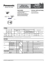
FEATURES<br />
1. Unique “Fine-mechanism” high<br />
performance contact construction<br />
realizes “fine-touch” comfortable<br />
operation feel.<br />
Covers wide range applications from<br />
consumer devices to FA equipment.<br />
2. LED illuminating unit has built-in<br />
resistor and diode for controlling<br />
current inside the LED bulb.<br />
3. Splashproof type protective<br />
construction (IP65).<br />
4. Contacts made of cadmium-free<br />
material. (Gold-clad contact)<br />
5. UL and CSA certified.<br />
RoHS Directive compatibility information<br />
http://www.mew.co.jp/ac/e/environment/<br />
ORDERING INFORMATION<br />
1. Illuminated pushbutton switches (LED illumination) and indicators (indicator lamps)<br />
Flange shapes<br />
(With transparent button type)<br />
2: 18 dia. projecting type<br />
3: 18 square flat type<br />
4: 18 × 24 flat type<br />
(With mushroom button type)<br />
0: 24 dia.<br />
ACEA 2<br />
Protective construction<br />
2: IP65<br />
No. of poles and operating characteristics<br />
0: Indicator (indicator lamp)<br />
1: Single-pole (1 Form C) momentary<br />
2: Double-pole (2 Form C) momentary<br />
3: Single-pole (1 Form C) alternate<br />
4: Double-pole (2 Form C) alternate<br />
Contact material<br />
0: Indicator (indicator lamp) (No contact)<br />
2: Low-level circuit type (Gold-clad contact)<br />
LED voltages and pushbutton colors<br />
Pushbutton color<br />
Color<br />
Red Orange Yellow Green Blue White (LED: opaque)<br />
LED voltage<br />
5 V DC<br />
12 V AC/DC<br />
24 V AC/DC<br />
1R<br />
2R<br />
3R<br />
4J<br />
5J<br />
6J<br />
4Y<br />
5Y<br />
6Y<br />
7G<br />
8G<br />
9G<br />
7L<br />
8L<br />
9L<br />
4X<br />
5X<br />
6X<br />
Color cap types<br />
Nil: Regular K: Mushroom button type ∗ There is no mushroom button type in the indicator (indicator lamp).<br />
05/2009<br />
7
NS Series (ACEA, ACBA, ACSA, ACKA)<br />
2. Pushbutton switches (non-illuminated types and transparent buttons However, the mushroom button type is not clear.)<br />
Flange shapes<br />
(With transparent button type)<br />
2: 18 dia. projecting type<br />
3: 18 square flat type<br />
4: 18 × 24 flat type<br />
(With mushroom button type)<br />
0: 24 dia.<br />
Protective construction<br />
2: IP65<br />
No. of poles and operating characteristics<br />
5: Single-pole (1 Form C) momentary<br />
6: Double-pole (2 Form C) momentary<br />
7: Single-pole (1 Form C) Alternate<br />
8: Double-pole (2 Form C) Alternate<br />
Contact material<br />
2: Low-level circuit type (Gold-clad contact)<br />
Types of color caps<br />
0: Transparent button K: Mushroom button<br />
ACBA 2 2<br />
Pushbutton colors<br />
Pushbutton color Red Orange Yellow Green Blue White Black<br />
Part No. R J Y G L X B<br />
Note: Mushroom button type is not available in orange.<br />
3. Selector switches<br />
Flange shapes<br />
3: 18 square flat type<br />
4: 18 × 24 flat type<br />
5: 18 dia. flat type<br />
Protective construction<br />
2: IP65<br />
Operation methods<br />
1: 2-notch manual reset<br />
3: 3-notch manual reset<br />
No. of poles<br />
6: 2 Form C<br />
Contact material<br />
4: Low-level circuit type (Gold-clad contact)<br />
ACSA 2 6 4<br />
8<br />
05/2009
4. Key selector switches<br />
Flange shapes<br />
3: 18 square flat type<br />
4: 18 × 24 flat type<br />
5: 18 dia. flat type<br />
NS Series (ACEA, ACBA, ACSA, ACKA)<br />
ACKA 2 2 4 1<br />
Protective construction<br />
2: IP65<br />
Operation methods and key removal positions<br />
11: 2-notch manual reset: OFF position<br />
12: 2-notch manual reset: ON position<br />
13: 2-notch manual reset: Both ON and OFF positions<br />
21: 2-notch automatic reset: OFF position<br />
37: 3-notch manual reset (Key can be removed at all 3 positions)<br />
No. of poles<br />
2: 2 Form C<br />
Contact material<br />
4: Low-level circuit type (Gold-clad contact)<br />
Key type<br />
1: Standard key<br />
TYPES<br />
1. Illuminated pushbutton switches (LED illumination)<br />
18 dia. projecting type 18 square flat type 18 × 24 flat type 24 dia. mushroom button type<br />
Mounting<br />
hole<br />
16mm dia.<br />
Form No. of poles Contact material<br />
18 dia. projecting type<br />
18 square flat type<br />
18 × 24 flat type<br />
24 dia. mushroom button type<br />
Notes) 1. The following combinations of numbers and letters are entered in the square and in the ❇ symbol to indicate the LED voltage and pushbutton color.<br />
2. The white type has a colorless transparent cap.<br />
Single pole<br />
Momentary<br />
Part No.<br />
Splashproof type (IP65)<br />
Alternate<br />
Part No.<br />
ACEA2212❇ ACEA2232❇<br />
Double poles ACEA2222❇ ACEA2242❇<br />
Single pole ACEA3212❇ ACEA3232❇<br />
Double poles Low-level circuit type<br />
ACEA3222❇ ACEA3242❇<br />
Single pole (Gold-clad contact)<br />
ACEA4212❇ ACEA4232❇<br />
Double poles ACEA4222❇ ACEA4242❇<br />
Single pole ACEA0212❇K ACEA0232❇K<br />
Double poles ACEA0222❇K ACEA0242❇K<br />
Color<br />
Pushbutton color<br />
White<br />
Red Orange Yellow Green Blue<br />
(Opaque LED)<br />
5 V DC 1R 4J 4Y 7G 7L 4X<br />
LED voltage 12 V AC/DC 2R 5J 5Y 8G 8L 5X<br />
24 V AC/DC 3R 6J 6Y 9G 9L 6X<br />
05/2009<br />
9
NS Series (ACEA, ACBA, ACSA, ACKA)<br />
2. Indicators (indicator lamps)<br />
18 dia. projecting type 18 square flat type 18 × 24 flat type<br />
Mounting<br />
hole<br />
16mm dia.<br />
Form<br />
Splashproof type (IP65)<br />
Part No.<br />
18 dia. projecting type ACEA2200❇<br />
18 square flat type ACEA3200❇<br />
18 × 24 flat type ACEA4200❇<br />
Notes) 1. The following combinations of numbers and letters are entered in the square and in the ❇ symbol to indicate the LED voltage and pushbutton color.<br />
Color<br />
Pushbutton color<br />
White<br />
Red Orange Yellow Green Blue<br />
(Opaque LED)<br />
5 V DC 1R 4J 4Y 7G 7L 4X<br />
LED voltage 12 V AC/DC 2R 5J 5Y 8G 8L 5X<br />
24 V AC/DC 3R 6J 6Y 9G 9L 6X<br />
2. The white type has a colorless transparent cap.<br />
3. Pushbutton switches (non-illuminated types and transparent buttons However, the mushroom button type is not clear.)<br />
18 dia. projecting type 18 square flat type 18 × 24 flat type 24 dia. mushroom button type<br />
Mounting<br />
hole<br />
16mm dia.<br />
Splashproof type (IP65)<br />
Form No. of poles Contact material<br />
Momentary<br />
Alternate<br />
Part No.<br />
Part No.<br />
18 dia. projecting type<br />
Single pole<br />
ACBA22520❇<br />
ACBA22720❇<br />
Double poles ACBA22620❇ ACBA22820❇<br />
18 square flat type<br />
Single pole ACBA32520❇ ACBA32720❇<br />
Double poles Low-level circuit type<br />
ACBA32620❇ ACBA32820❇<br />
18 x 24 flat type<br />
Single pole (Gold-clad contact)<br />
ACBA42520❇ ACBA42720❇<br />
Double poles ACBA42620❇ ACBA42820❇<br />
24 dia. Mushroom button<br />
Single pole ACBA0252K❇ ACBA0272K❇<br />
Double poles ACBA0262K❇ ACBA0282K❇<br />
Notes) 1. The following letter indicating the pushbutton color is entered in place of the ❇ symbol.<br />
Pushbutton color Red Orange Yellow Green Blue White Black<br />
Part No. R J Y G L X B<br />
2. The white type has a colorless transparent cap.<br />
3. The mushroom button type is not available in orange.<br />
10<br />
05/2009
4. Selector switches<br />
NS Series (ACEA, ACBA, ACSA, ACKA)<br />
18 square flat type 18 × 24 flat type 18 dia. flat type<br />
1) 2-notch manual reset type<br />
Mounting<br />
hole<br />
16mm dia.<br />
2) 3-notch manual reset type<br />
Mounting<br />
hole<br />
16mm dia.<br />
5. Key selector switches<br />
Form No. of poles Contact material<br />
Splashproof type (IP65)<br />
Part No.<br />
18 square flat type<br />
ACSA32164<br />
Low-level circuit type<br />
18 × 24 flat type Double poles<br />
ACSA42164<br />
(Gold-clad contact)<br />
18 dia. projecting type ACSA52164<br />
Form No. of poles Contact material<br />
Splashproof type (IP65)<br />
Part No.<br />
18 square flat type<br />
ACSA32364<br />
Low-level circuit type<br />
18 × 24 flat type Double poles<br />
ACSA42364<br />
(Gold-clad contact)<br />
18 dia. projecting type ACSA52364<br />
18 square flat type 18 × 24 flat type 18 dia. flat type<br />
1) 2-notch manual reset type<br />
Splashproof type (IP65)<br />
Mounting<br />
hole<br />
16mm dia.<br />
2) 2-notch automatic reset type<br />
Mounting<br />
hole<br />
16mm dia.<br />
3) 3-notch manual reset type<br />
Form No. of poles Contact material<br />
Key removed in<br />
OFF position<br />
Key removed in<br />
ON position<br />
Key removed in both<br />
OFF and ON positions<br />
Part No. Part No. Part No.<br />
18 square flat type<br />
ACKA3211241 ACKA3212241 ACKA3213241<br />
Low-level circuit type<br />
18 × 24 flat type Double poles<br />
ACKA4211241 ACKA4212241 ACKA4213241<br />
(Gold-clad contact)<br />
18 dia. flat type ACKA5211241 ACKA5212241 ACKA5213241<br />
Form No. of poles Contact material<br />
Splashproof type (IP65)<br />
Key removed in OFF position<br />
Part No.<br />
18 square flat type<br />
ACKA3221241<br />
Low-level circuit type<br />
18 × 24 flat type Double poles<br />
ACKA4221241<br />
(Gold-clad contact)<br />
18 dia. flat type ACKA5221241<br />
Splashproof type (IP65)<br />
Mounting<br />
hole<br />
16mm dia.<br />
Form No. of poles Contact material<br />
Key removed in all 3 positions<br />
Part No.<br />
18 square flat type<br />
ACKA3237241<br />
Low-level circuit type<br />
18 × 24 flat type Double poles<br />
ACKA4237241<br />
(Gold-clad contact)<br />
18 dia. flat type ACKA5237241<br />
05/2009<br />
11
NS Series (ACEA, ACBA, ACSA, ACKA)<br />
SPECIFICATIONS<br />
1. Contact rating<br />
1) Gold-clad contact<br />
Load AC rating DC rating<br />
Resistive load 0.3 A 250 V AC 1.0 A 30 V DC<br />
Minute load<br />
1 mA 5 V AC/DC*<br />
Note) The usable range for the minute load indicated by the asterisk may fluctuate depending on the usage conditions and the type of load.<br />
2. LED rating<br />
Rated operating<br />
voltage<br />
Operating voltage<br />
range<br />
Rated current<br />
LED life<br />
(reference value)<br />
Equivalence circuit<br />
Lighted colors<br />
(+)<br />
(–)<br />
Red, orange, yellow,<br />
opaque<br />
5 V DC 5 V DC±5% 8 mA<br />
12 V AC/DC 12 V AC/DC±10% 9 mA/8 mA<br />
Approx. 50,000 hours<br />
(with full direct current<br />
lighting at 50% of<br />
initial intensity)<br />
(+)<br />
(–)<br />
Green, blue<br />
Red, orange, yellow,<br />
green, blue, opaque<br />
24 V AC/DC 24 V AC/DC±10% 9 mA/8 mA<br />
LED chip<br />
Protective diode<br />
Zener diode<br />
Note) The current limiting resistor and protective diode are built into the LED bulb.<br />
3. Characteristics<br />
Item<br />
Specifications<br />
Ambient temperature: –25 to +55°C (Not freezing)<br />
Standard usage condition<br />
(Storage temperature: –30 to +80°C)<br />
Relative humidity: 45 to 85%<br />
Contact resistance<br />
Max. 50 mΩ (initial)<br />
Insulation resistance<br />
Min. 100 MΩ (500 V DC megger)<br />
Between metal charging part and non-metal charging part: 2,000 V AC for 1 min.<br />
Dielectric strength<br />
Between terminals with unlike poles: 2,000 V AC for 1 min.<br />
Switch section<br />
Between terminals with like poles: 1,000 V AC for 1 min.<br />
Between contact terminals and lamp terminals: 1,500 V AC for 1 min.<br />
Illuminating section Between charging part and ground: 2,000 V AC for 1 min.<br />
Vibration resistance Malfunctioning 10 to 55 Hz at single amplitude of 0.75 mm<br />
Shock resistance<br />
Durability 500 m/s 2<br />
Malfunctioning 200 m/s 2<br />
Momentary: Min. 10 6 times<br />
Mechanical Alternate: Min. 10 5 times<br />
Expected life<br />
Selector switch (incl. those with keys): Min. 2.5 × 10 5 times<br />
<strong>Electric</strong>al<br />
Min. 10 5 times, switching frequency 1,200 times/hr.<br />
Alternate: Min. 5 × 10 4 times<br />
Protective construction<br />
Splashproof and oil resistance type IP65 (IEC60529)<br />
12<br />
05/2009
8<br />
NS Series (ACEA, ACBA, ACSA, ACKA)<br />
DIMENSIONS (unit: mm)<br />
1. Illuminated pushbutton switches and indicators<br />
18 dia. projecting type 18 square flat type 18 × 24 flat type 24 dia. mushroom button type<br />
(Illuminated pushbutton switches and indicators)<br />
18 dia. projecting type 18 square flat type 18 × 24 flat type<br />
18 dia.<br />
(TOP)<br />
Panel thickness: 0.5 to 6mm<br />
Rubber washer<br />
Whirl-stop plate<br />
Lock nut<br />
Terminal width: 2.8 × 0.5t<br />
2.5 3<br />
18<br />
5<br />
18 24<br />
0.6<br />
9<br />
22<br />
1<br />
5<br />
6 6<br />
24 dia. mushroom button type<br />
23.5 dia.<br />
(24 dia. mushroom button type)<br />
Soldering terminal width: 2.8 × 0.5t<br />
5<br />
5<br />
N C<br />
N O<br />
C<br />
Notes) 1. Indicators have only lamp terminals, and do not have contact terminals.<br />
2. There is no mushroom button type in the indicator.<br />
5.7<br />
12.5<br />
0.6<br />
22<br />
1<br />
8<br />
WIRING DI<strong>AG</strong>RAM (BOTTOM VIEW)<br />
(Illuminated pushbutton switches)<br />
(TOP)<br />
(Indicators)<br />
(TOP)<br />
NC1<br />
NC2<br />
NO1<br />
NO2<br />
Lamp terminal<br />
(+)<br />
C1<br />
C2<br />
Lamp terminal<br />
(–)<br />
Lamp terminal<br />
(+)<br />
Lamp terminal<br />
(–)<br />
(Single pole “1 Form C” types have only the left terminal.)<br />
Mounting hole diagram, and recommended minimum mounting pitch<br />
18 dia. projecting and<br />
18 × 24 flat type<br />
18 square flat types<br />
Mushroom button type<br />
16.2 +0.2<br />
0 dia.<br />
16.2 +0.2<br />
0 dia.<br />
Min. 28.5<br />
16.2 +0.2<br />
–0 dia.<br />
18<br />
18<br />
Min. 28.5<br />
18<br />
24<br />
Note) Operability should be taken into consideration when deciding the mounting pitch.<br />
05/2009<br />
13
8<br />
NS Series (ACEA, ACBA, ACSA, ACKA)<br />
2. Pushbutton switches<br />
18 dia. projecting type 18 square flat type 18 × 24 flat type 24 dia. mushroom button type<br />
(Illuminated pushbutton switches and indicators)<br />
18 dia. projecting type 18 square flat type 18 × 24 flat type<br />
18 dia.<br />
(TOP)<br />
Panel thickness: 0.5 to 6mm<br />
Rubber washer<br />
Whirl-stop plate<br />
Lock nut<br />
Terminal width: 2.8 × 0.5t<br />
2.5 3<br />
18<br />
5<br />
18 24<br />
0.6<br />
9<br />
22<br />
1<br />
5<br />
6 6<br />
24 dia. mushroom button type<br />
23.5 dia.<br />
(24 dia. mushroom button type)<br />
Soldering terminal width: 2.8 × 0.5t<br />
5<br />
5<br />
N C<br />
N O<br />
C<br />
Note) Pushbutton switches have only contact terminals, and do not have lamp<br />
terminals.<br />
5.7<br />
12.5<br />
0.6<br />
22<br />
1<br />
8<br />
WIRING DI<strong>AG</strong>RAM (BOTTOM VIEW)<br />
(Pushbutton switches)<br />
(TOP)<br />
NC1<br />
NC2<br />
NO1<br />
C1<br />
NO2<br />
C2<br />
(Single pole “1 Form C” types have only the left terminal.)<br />
Mounting hole diagram, and recommended minimum mounting pitch<br />
18 dia. projecting and<br />
18 × 24 flat type<br />
18 square flat types<br />
Mushroom button type<br />
16.2 +0.2<br />
0 dia.<br />
16.2 +0.2<br />
0 dia.<br />
Min. 28.5<br />
16.2 +0.2<br />
–0 dia.<br />
18<br />
18<br />
Min. 28.5<br />
18<br />
24<br />
Note) Operability should be taken into consideration when deciding the mounting pitch.<br />
14<br />
05/2009
3. Selector switches/Key selector switches<br />
1) Selector switches<br />
NS Series (ACEA, ACBA, ACSA, ACKA)<br />
18 square flat type 18 × 24 flat type 18 dia. flat type<br />
18 square flat type 18 × 24 flat type 18 dia. flat type<br />
18 dia.<br />
Panel thickness: 0.5 to 6mm<br />
Rubber washer<br />
Whirl-stop plate<br />
Lock nut<br />
Terminal width: 2.8 × 0.5t<br />
2.5 3<br />
18<br />
5<br />
5<br />
18 24<br />
15.5<br />
8<br />
22<br />
1<br />
8<br />
2) Key selector switches<br />
18 square flat type 18 × 24 flat type 18 dia. flat type<br />
18 square flat type 18 × 24 flat type 18 dia. flat type<br />
Panel thickness: 0.5 to 6mm<br />
Rubber washer<br />
Whirl-stop plate<br />
Terminal width: 2.8 × 0.5t<br />
Lock nut<br />
2.5 3<br />
18<br />
5<br />
5<br />
NC<br />
NO<br />
C<br />
1<br />
18 24<br />
18 dia.<br />
26<br />
22<br />
8<br />
WIRING DI<strong>AG</strong>RAM (BOTTOM VIEW)<br />
(Selector switches/Key selector switches)<br />
(TOP)<br />
NC1 NC2<br />
Mounting hole diagram, and recommended minimum<br />
mounting pitch<br />
18 dia. projecting and<br />
18 × 24 flat type<br />
18 square flat types<br />
16.2 +0.2<br />
0 dia.<br />
16.2 +0.2<br />
0 dia.<br />
NO1<br />
NO2<br />
18<br />
18<br />
C1<br />
C2<br />
18<br />
24<br />
Note) Operability should be taken into consideration when deciding the mounting<br />
pitch.<br />
Internal circuit diagram<br />
Notch specifications<br />
Notch positions (TOP VIEW)<br />
Contact<br />
1 (left) 0 (center) 2 (right)<br />
arrangement<br />
90°–<br />
2-notch<br />
1 2<br />
Stopping at each position<br />
1<br />
2<br />
Right returm<br />
2 contacts<br />
(2 Form C)<br />
Left contact<br />
NO NC<br />
C<br />
Right contact<br />
NO NC<br />
C<br />
Left contact<br />
NO NC<br />
C<br />
Right contact<br />
NO NC<br />
C<br />
45°–<br />
3-notch<br />
0<br />
1 2<br />
Stopping at each position<br />
2 contacts<br />
(2 Form C)<br />
Left contact<br />
NO NC<br />
C<br />
Right contact<br />
NO NC<br />
C<br />
Left contact<br />
NO NC<br />
C<br />
Right contact<br />
NO NC<br />
C<br />
Left contact<br />
NO NC<br />
C<br />
Right contact<br />
NO NC<br />
C<br />
05/2009<br />
15
NS Series Accessories and maintenance items<br />
NS Series Accessories and maintenance items<br />
Ring tightener<br />
Part No.<br />
Specifications<br />
Unit<br />
ACDL1800<br />
Metal<br />
1 pc.<br />
RoHS Directive compatibility information<br />
http://www.mew.co.jp/ac/e/environment/<br />
• This tool is convenient for tightening the<br />
lock nuts used when mounting the unit<br />
on a panel.<br />
• When tightening rings, the torque<br />
should be between 0.68 and 0.88 N·m<br />
(7.0 to 9.0 kgf·cm).<br />
Lamp replacement tool<br />
• This tool is used to replace lamps when<br />
LEDs are being installed or removed.<br />
Removal tool<br />
• This tool is used to pull off the operating<br />
parts (color cap, inscribed plate, and<br />
holder) of illuminated pushbuttons,<br />
indicators, and pushbutton switches.<br />
Part No.<br />
Specifications<br />
Unit<br />
Part No.<br />
Specifications<br />
Unit<br />
ACDA1802<br />
For illuminated<br />
pushbuttons and indicators<br />
1 pc.<br />
ACDL1804<br />
Metal<br />
1 pc.<br />
LEDs (parts for maintenance)<br />
Part No. ACDA1861❇ ACDA1861❇ ACDA1861❇<br />
Rated operating voltage 5 V DC±5% 12 V AC/DC±10% 24 V AC/DC±10%<br />
Rated current 8 mA 9 mA/8 mA 9 mA/8 mA<br />
Unit<br />
10 pcs.<br />
Note) The following number/letter combinations indicating the LED voltage and pushbutton color should be<br />
entered in the square indicated by the asterisk after the part number.<br />
• For illuminated pushbuttons and<br />
indicators (indicator lamps), the LED is<br />
built-in. These LEDs should be ordered<br />
only if spares are required.<br />
• The asterisk in the pack part number is<br />
where the letter to indicate the lamp<br />
color is inserted.<br />
Pushbutton color Red Orange Yellow Green Blue<br />
White<br />
Opaque LED<br />
5 V DC 1R 4J 4Y 7G 7L 4X<br />
LED voltage 12 V AC/DC 2R 5J 5Y 8G 8L 5X<br />
24 V AC/DC 3R 6J 6Y 9G 9L 6X<br />
Maintenance parts should be installed by an engineer with specialized expertise in electrical components.<br />
When placing orders, please specify the number of marketing units.<br />
16<br />
05/2009
R22<br />
Protective cover<br />
NS Series Accessories and maintenance items<br />
DIMENSIONS (unit: mm)<br />
18 dia. 18 square (ACDL1810) 18 × 24 (ACDL1811)<br />
18<br />
24<br />
13<br />
13<br />
• This cover is designed to prevent<br />
erroneous operation.<br />
• The cover opens 180°, and closes by<br />
means of a return spring.<br />
• Protective construction: Spray-resistant<br />
type (IP65)<br />
23.5<br />
10.5<br />
45.5 min.<br />
23.5<br />
10.5<br />
45.5 min.<br />
19 min.<br />
25 min.<br />
Return<br />
spring<br />
34<br />
Panel thickness:<br />
0.5 to 5mm<br />
Type<br />
For 18 dia./<br />
18 square<br />
For 18 × 24<br />
Part No. ACDL1810 ACDL1811<br />
Unit<br />
10 pcs.<br />
33<br />
14<br />
Protective cover installation diagram<br />
Dustproof cover<br />
DIMENSIONS (unit: mm)<br />
18 dia.<br />
(ACDL1812)<br />
18 square<br />
(ACDL1813)<br />
18 × 24<br />
(ACDL1814)<br />
24 dia.<br />
24<br />
30<br />
• The minimum installation pitch will be<br />
different if the dustproof cover is being<br />
used.<br />
• Ambient usage temperature:<br />
–10 to +55°C<br />
• Material: Elastomer (front/transparent)<br />
and polypropylene (back/nontransparent<br />
black)<br />
0.3 13<br />
7.5<br />
Waterproof<br />
seal for<br />
dustproof<br />
cover<br />
0.3 13<br />
7.5<br />
(Minimum mounting pitch)<br />
• 18 dia. and 18 square types<br />
Waterproof<br />
seal for<br />
dustproof<br />
cover<br />
• 18 × 24 type<br />
24<br />
0.3 13<br />
7.5<br />
Waterproof<br />
seal for<br />
dustproof<br />
cover<br />
13<br />
Panel thickness:<br />
0.5 to 5mm<br />
Dustproof cover<br />
installation diagram<br />
16.2 +0.2 0 dia.<br />
16.2 +0.2<br />
0 dia.<br />
24<br />
24<br />
24<br />
30<br />
Note) When deciding the mounting pitch, make sure the cover has enough room to operate properly.<br />
Type<br />
For 18 dia.<br />
For 18<br />
square<br />
For 18 × 24<br />
Part No. ACDL1812 ACDL1813 ACDL1814<br />
Unit<br />
10 pcs.<br />
17<br />
05/2009
NS Series Accessories and maintenance items<br />
Insulating terminal cover<br />
Part No.<br />
ACDA1850<br />
Specifications Opaque nylon<br />
Unit<br />
10 pcs.<br />
DIMENSIONS (unit: mm)<br />
17.3<br />
16.8 dia.<br />
• This terminal cover is made of an<br />
opaque nylon material.<br />
Note) When wiring the terminal, insert the lead into<br />
the hole in the insulating terminal cover before<br />
soldering it.<br />
33.5<br />
Dimension at inner back of panel<br />
when mounting insulating terminal<br />
cover: 47 mm<br />
Mounting hole plug (rubber)<br />
Part No.<br />
Specifications<br />
Unit<br />
ACDL1820<br />
Nitrile rubber (black)<br />
Protective construction:<br />
IP65<br />
10 pcs.<br />
DIMENSIONS (unit: mm)<br />
18 dia.<br />
16.5 dia.<br />
2 6<br />
Mounting<br />
hole<br />
16.2 +0.2<br />
0 dia.<br />
Mounting hole plug (metal)<br />
Part No.<br />
Specifications<br />
Unit<br />
ACDL1821<br />
Made of metal; protective<br />
construction: IP65<br />
10 pcs.<br />
DIMENSIONS (unit: mm)<br />
2.5 12<br />
17.8 dia.<br />
Mounting<br />
hole<br />
16.2 +0.2<br />
0 dia.<br />
Seal<br />
Lock nut<br />
Inscribed plate (maintenance part)<br />
Shape Round Square Rectangular<br />
Part No. ACDL1830 ACDL1831 ACDL1832<br />
Unit<br />
1 pack (5 plates)<br />
• Color: Opaque<br />
• Material: Methacrylic resin<br />
Maintenance parts should be installed by an engineer with specialized expertise in electrical components.<br />
When placing orders, please specify the number of marketing units.<br />
18<br />
05/2009
Cautions For Use of the NS Series<br />
Cautions For Use of the NS Series<br />
Cautions For Use<br />
1. Mounting and removing the color<br />
cap and inscribed plate<br />
1) Removing<br />
Grip the grooved part of the color cap<br />
with the removal tool (ACDL1804), and<br />
pull it towards you to remove the<br />
operating parts (the color cap, inscribed<br />
plate and lens holder). The inscribed<br />
plate can be removed by pushing the<br />
color cap outward from the back side,<br />
freeing the grooved section that joins it to<br />
the holder. The plate is inscribed on one<br />
surface, as shown below, and not on the<br />
other side.<br />
2) Mounting<br />
Place the inscribed plate in the holder,<br />
line up the grooves in the color cap and<br />
the holder, and press them together.<br />
When doing this, make sure the inscribed<br />
plate is facing the correct direction. After<br />
the inscribed plate and color cap have<br />
been mounted in the holder, insert the<br />
assembled unit in the main unit, making<br />
sure it faces the correct direction.<br />
2. Mounting and removing LEDs<br />
[Removing the LED]<br />
Use a lamp replacement tool to remove<br />
the LED. Do not use pliers.<br />
[Mounting the LED]<br />
Install using a lamp replacement tool. Be<br />
sure that the orientation is correct when<br />
mounting.<br />
10 dia.<br />
Grooved<br />
section<br />
Joining grooves<br />
Inscribed<br />
surface<br />
Color cap Inscribed plate Holder<br />
Mounting side<br />
55<br />
Removing side<br />
9 dia.<br />
3. Precautions when mounting the<br />
panel<br />
Use a separately sold ring tightener when<br />
mounting to a panel. The use of needlenose<br />
pliers or similar and the application<br />
of excessive tightening force can cause<br />
damage to the ring. The recommended<br />
ring tightening torque is 0.88 N·m.<br />
4. Precautions when connecting<br />
wiring<br />
Terminals should be soldered at 20 W for<br />
less than 5 seconds, or at 260°C for less<br />
than 3 seconds, without applying external<br />
force. When doing this work, make sure<br />
the soldering iron does not come in<br />
contact with the switch itself, and that,<br />
when connecting the wiring, no tensile<br />
force is applied to the terminal. Avoid<br />
bending the terminal or subjecting it to<br />
excessive force. Non-corroding liquid<br />
resin flux should be used.<br />
5. Caution regarding LED service<br />
voltage<br />
A service voltage of 5 V DC indicates a<br />
perfect direct current value.<br />
6. Handling and Usage Precautions<br />
1) Aggregate tight mounting<br />
Please be aware that heat caused by<br />
aggregate tight mounting of indicator<br />
lamps and illuminated pushbutton<br />
switches or continuously lit lamps can<br />
cause the ambient temperature to<br />
exceed the prescribed amount. Measures<br />
must be taken to ventilate or lower the<br />
operation voltage if the mounting panel is<br />
not metal or if the product is being used<br />
in a sealed control panel.<br />
2) Replacement of buttons (illuminating<br />
and non-illuminating)<br />
Do not replace alternate type buttons<br />
(illuminating and non-illuminating) when<br />
they are locked. (Replacing while locked<br />
might damage the internal mechanism.)<br />
You must release the locks before<br />
replacing.<br />
3) Storage and place of use<br />
(1) Please use within the working<br />
ambient temperature and humidity<br />
ranges given on the ratings display.<br />
(2) When using in a location where oil,<br />
water and dirt are present, install a dust<br />
cover so that foreign substances cannot<br />
enter the sliding part of the pushbutton.<br />
4) Contact (microswitch)<br />
When using identical NC (normal close)<br />
and NO (normal open) microswitch<br />
contacts, do not connect to the wrong<br />
voltage or to the wrong type of power<br />
supply. Doing so will cause a dead short.<br />
5) Oil resistance<br />
The product has been evaluated with<br />
commonly used standard machining oil<br />
and cooling oil. Please inquire about<br />
other oils, since use of some special oils<br />
may not be possible.<br />
05/2009<br />
19
ND Series: 16 dia. types (ACEL, ACBL, ACSL, ACKL)<br />
Illuminated pushbutton,<br />
non-illuminated pushbutton,<br />
selector,<br />
key selector switches<br />
Bright, clear illumination (ultra-high intensity LED used)<br />
Separate mounting model features removable lock lever<br />
TÜV Rheinland<br />
ND Series<br />
(mounting hole 16 dia. type)<br />
Tight, space-saving mounting<br />
2. Emergency pushbutton switches<br />
equipped with safety lock mechanism.<br />
Contacts have forced contact<br />
separation mechanism. Two button<br />
diameters available, 25 and 40.<br />
1) Safety lock mechanism<br />
A safety lock mechanism is used in which<br />
the contact does not move until the<br />
pushbutton has completely locked.<br />
Because the contact does not operate<br />
unless the button has been pressed all<br />
the way down, there is no danger of the<br />
machine suddenly stopping because of a<br />
malfunction caused by something coming<br />
in contact with the button, and no loss<br />
from such situations.<br />
FEATURES<br />
1. Bright, clear LED illumination<br />
1) Uses brilliantly illuminating LEDs that<br />
are much brighter than incandescent<br />
bulbs.<br />
2) Brightness greatly increased for vastly<br />
improved recognition and safety. Yellow<br />
and green are particularly easy to<br />
distinguish.<br />
Makers who are especially concerned<br />
about product liability laws and worker<br />
safety and sanitation are calling for<br />
machines that are designed and<br />
manufactured based on the ISO12100<br />
series of international safety standards<br />
(general regulations governing basic<br />
conceptual design for machine safety).<br />
With the ISO12100 series, the manmachine<br />
interface must be designed so<br />
that the status of the machine can be<br />
recognized clearly and correctly by<br />
anyone running the machine, without<br />
special training or expertise. For that<br />
reason, display lamp colors are<br />
standardized under IEC60073,<br />
IEC60204-1 and other standards cited in<br />
the ISO12100 series, and are covered by<br />
JIS standards as well. The LED<br />
illumination of the ND type meets safety<br />
needs such as these, and beyond.<br />
Note) IEC60073:<br />
JIS C 0448 Colors for Display Units and<br />
Operation Devices<br />
IEC60204-1:<br />
JIS B 9960-1 Safety of Machines and<br />
<strong>Electric</strong>al Units of Machines<br />
20<br />
Display lamp colors and meanings<br />
indicating machine status (taken from<br />
International <strong>Electric</strong>al Standards<br />
Conference IEC-60073 and 60204-1)<br />
Operator<br />
Color Meaning Explanation<br />
action<br />
Red<br />
Yellow<br />
Caution<br />
Hazardous<br />
situation<br />
Problem<br />
status/urgent<br />
or critical<br />
situation<br />
Action<br />
appropriate to<br />
hazardous<br />
situation<br />
Visual<br />
monitoring and<br />
(or)<br />
intervention<br />
Green Normal Normal status As appropriate<br />
Blue<br />
White<br />
Emergency<br />
Obligatory<br />
Neutral<br />
Displays status<br />
of action<br />
required by<br />
operator<br />
Any other<br />
status; Can be<br />
used when<br />
using red,<br />
yellow, green,<br />
or blue might<br />
be interpreted<br />
erroneously.<br />
Obligatory<br />
action<br />
Visual<br />
monitoring<br />
3) Power consumption greatly reduced<br />
(12 V type).<br />
The power consumption has been<br />
reduced by 60% in the 12 V type<br />
(mounting hole 16 dia. type).<br />
4) Continuous illumination with no need<br />
for replacement for 5 years (50,000<br />
hours).<br />
5) Products available in 6 illuminated<br />
colors: red, orange, yellow, green, blue,<br />
and white.<br />
mm<br />
Rated current<br />
12 V AC/<br />
DC type<br />
Mounting hole<br />
16 dia. type<br />
8 mA (20 mA in<br />
previous model)<br />
05/2009<br />
Mounting hole<br />
22 dia. type<br />
10 mA (20 mA in<br />
previous model)<br />
2) Forced contact separation mechanism<br />
The mechanism is designed so that the<br />
button operation force is used, as is, as<br />
the contact separation force. Therefore,<br />
the circuit will shut off perfectly even if a<br />
problem happens to occur such as the<br />
contact welding shut. (Conforms to<br />
EN60947-5-1 Annex K.)<br />
3) Two button diameters available, 25 and<br />
40.<br />
3. Nice, light switching feel. Light<br />
operation load due to snap action<br />
mechanism. Short stroke type.<br />
Relationship between operation load<br />
and stroke (Mounting hole 16 dia. type:<br />
1 Form C contact momentary action)<br />
Operation load (g)<br />
350<br />
300<br />
250<br />
200<br />
150<br />
100<br />
50<br />
0<br />
1 2 3<br />
Stroke (mm)<br />
1) Stroke: 3 mm<br />
2) Mechanical life<br />
(mounting hole 16 dia. type)<br />
Momentary type: Min. 2 × 10 6<br />
(4 times better than previous)<br />
Alternate type: Min. 2.5 × 10 5<br />
(2.5 times better than previous)
4. Removal/installation type with lock<br />
lever system.<br />
Smooth installation now possible.<br />
1) New tight mounting type added. Space<br />
saving realized with small installation<br />
area.<br />
2) It is easy to install in tight spaces and<br />
maintenance is easy.<br />
3) Operation efficiency is greatly<br />
increased since surface installation and<br />
wiring operations can be carried out<br />
separately.<br />
Mounting hole 16 dia. type<br />
Lock lever<br />
ND Series: 16 dia. types (ACEL, ACBL, ACSL, ACKL)<br />
Mounting hole 16 dia. type exterior<br />
configuration diagram<br />
Stroke: 3mm<br />
T O P<br />
9mm<br />
36mm<br />
(when set)<br />
9mm<br />
5. Mushroom button type for easier<br />
operation.<br />
6. Splashproof type protective<br />
construction (IP65).<br />
Conforms to IEC 60529.<br />
7. Safety standard<br />
1) UL and CSA certified (excluding<br />
buzzer).<br />
2) Conforms to EN standard (excluding<br />
buzzer), has received CE marking.<br />
8. Durability<br />
Thermoplastic materials are used for<br />
durability in the outer casing and<br />
installation points.<br />
9. Contacts made of cadmium-free<br />
material.<br />
RoHS Directive compatibility information<br />
http://www.mew.co.jp/ac/e/environment/<br />
ORDERING INFORMATION<br />
1. Illuminated pushbutton switches (LED illumination) and indicators (display lamps)<br />
Illumination type<br />
EL: LED type<br />
ACEL 2<br />
Mounting holes and flange shapes<br />
(With transparent button type)<br />
Mounting hole Flange shape<br />
2: 16 dia. 18 dia. projecting type<br />
3: 16 dia. 18 square flat type<br />
4: 16 dia. 18 × 24 flat type<br />
(With mushroom button type)<br />
Mounting hole<br />
0: 16 dia.<br />
5: 16 dia.<br />
Protective construction<br />
2: Splashproof type (IP65)<br />
Flange shape<br />
24 dia.<br />
30 dia.<br />
No. of poles and operating characteristics<br />
0: Indicator (indicator lamp)<br />
1: Single-pole (1 Form C) momentary<br />
2: Double-pole (2 Form C) momentary<br />
Contact material<br />
0: Indicator (indicator lamp) (No contact)<br />
1: Standard type (Silver contact)<br />
3: Single-pole (1 Form C) alternate<br />
4: Double-pole (2 Form C) alternate<br />
2: Low-level circuit type (Gold-clad contact)<br />
LED voltages and pushbutton colors<br />
Pushbutton color<br />
Color<br />
Red Orange Yellow Green Blue White (LED: opaque)<br />
LED voltage<br />
5 V DC<br />
12 V AC/DC<br />
24 V AC/DC<br />
1R<br />
2R<br />
3R<br />
4J<br />
5J<br />
6J<br />
4Y<br />
5Y<br />
6Y<br />
7G<br />
8G<br />
9G<br />
7L<br />
8L<br />
9L<br />
4X<br />
5X<br />
6X<br />
Terminal shape and mounting dimensions<br />
Nil: solderable tab terminal, tight mounting<br />
3: Terminal for PC board and tight mounting (only gold contact)<br />
Color cap types<br />
Nil: Regular K: Mushroom button type ∗ There is no mushroom button type in the indicator (indicator lamp).<br />
05/2009<br />
21
ND Series: 16 dia. types (ACEL, ACBL, ACSL, ACKL)<br />
2. Pushbutton switches (non-illuminated types and transparent buttons)<br />
Mounting holes and flange shapes<br />
(With transparent button type)<br />
Mounting hole Flange shape<br />
2: 16 dia. 18 dia. projecting type<br />
3: 16 dia. 18 square flat type<br />
4: 16 dia. 18 × 24 flat type<br />
(With mushroom button type)<br />
Mounting hole<br />
0: 16 dia.<br />
5: 16 dia.<br />
Flange shape<br />
24 dia.<br />
30 dia.<br />
ACBL 2<br />
Protective construction<br />
2: Splashproof type (IP65)<br />
No. of poles and operating characteristics<br />
5: Single-pole (1 Form C) momentary<br />
6: Double-pole (2 Form C) momentary<br />
7: Single-pole (1 Form C) Alternate<br />
8: Double-pole (2 Form C) Alternate<br />
Contact material<br />
1: Standard type (Silver alloy contact) 2: Low-level circuit type (Gold-clad contact)<br />
Types of color caps<br />
0: Transparent button K: Mushroom button<br />
Pushbutton colors<br />
Transparent button<br />
(Mushroom button: not clear)<br />
Note: Mushroom button type is not available in orange.<br />
R J Y G L X B<br />
Red Orange Yellow Green Blue White Black<br />
Terminal shape and mounting dimensions<br />
Nil: solderable tab terminal, tight mounting<br />
3: Terminal for PC board and tight mounting (only gold contact)<br />
3. Selector switches<br />
Mounting holes and flange shapes<br />
<br />
3: 16 dia. 18 square flat type<br />
4: 16 dia. 18 × 24 flat type<br />
5: 16 dia. 18 dia. flat type<br />
ACSL 2<br />
Protective construction<br />
2: Splashproof type (IP65)<br />
Operation methods<br />
1: 2-notch manual reset<br />
3: 3-notch manual reset (Double poles only)<br />
No. of poles<br />
5: Single pole (2-notch only)<br />
Contact material<br />
3: Standard type (Silver contact)<br />
Note) Manual reset: Switch is rotated to turn it on and remains on when released.<br />
Automatic reset: Switch is rotated to turn it on and goes off when released.<br />
6: Double poles<br />
4: Low-level circuit type (Gold-clad contact)<br />
Note: Terminals for PC board are also possible.<br />
22<br />
05/2009
4. Key selector switches<br />
Mounting holes and flange shapes<br />
<br />
3: 16 dia. 18 square flat type<br />
4: 16 dia. 18 × 24 flat type<br />
5: 16 dia. 18 dia. flat type<br />
ND Series: 16 dia. types (ACEL, ACBL, ACSL, ACKL)<br />
ACKL 2 1<br />
Protective construction<br />
2: Splashproof type (IP65)<br />
Operation methods and key removal positions<br />
11: 2-notch manual reset: OFF position<br />
12: 2-notch manual reset: ON position<br />
13: 2-notch manual reset: Both ON and OFF positions<br />
21: 2-notch automatic reset: OFF position (mounting hole 16 dia. type only)<br />
37: 3-notch manual reset (no single pole; double poles only) (Key can be removed at all 3 positions)<br />
No. of poles<br />
1: Single pole 2: Double poles<br />
Contact material<br />
3: Standard type (Silver contact) 4: Low-level circuit type (Gold-clad contact)<br />
Key type<br />
1: Standard key<br />
Note: Terminals for PC board are also possible.<br />
05/2009<br />
23
ND Series: 16 dia. types (ACEL, ACBL, ACSL, ACKL)<br />
TYPES<br />
1. Illuminated pushbutton switches (LED illumination)<br />
18 dia. projecting type 18 square flat type 18 × 24 flat type 24 dia. mushroom button type 30 dia. mushroom button type<br />
Splashproof type (IP65)<br />
Form No. of poles Contact material<br />
Momentary<br />
Alternate<br />
Part No.<br />
Part No.<br />
Standard type (Silver contact) ACEL2211❇ ACEL2231❇<br />
18 dia. Single pole<br />
Low-level circuit type (Gold-clad contact) ACEL2212❇ ACEL2232❇<br />
projecting<br />
type<br />
Standard type (Silver contact) ACEL2221❇ ACEL2241❇<br />
Double poles<br />
Low-level circuit type (Gold-clad contact) ACEL2222❇ ACEL2242❇<br />
Standard type (Silver contact) ACEL3211❇ ACEL3231❇<br />
Single pole<br />
18 square<br />
Low-level circuit type (Gold-clad contact) ACEL3212❇ ACEL3232❇<br />
flat type<br />
Standard type (Silver contact) ACEL3221❇ ACEL3241❇<br />
Double poles<br />
Low-level circuit type (Gold-clad contact) ACEL3222❇ ACEL3242❇<br />
Standard type (Silver contact) ACEL4211❇ ACEL4231❇<br />
Single pole<br />
18 × 24<br />
Low-level circuit type (Gold-clad contact) ACEL4212❇ ACEL4232❇<br />
flat type<br />
Standard type (Silver contact) ACEL4221❇ ACEL4241❇<br />
Double poles<br />
Low-level circuit type (Gold-clad contact) ACEL4222❇ ACEL4242❇<br />
Standard type (Silver contact) ACEL0211❇K ACEL0231❇K<br />
24 dia. Single pole<br />
Low-level circuit type (Gold-clad contact) ACEL0212❇K ACEL0232❇K<br />
mushroom<br />
button type<br />
Standard type (Silver contact) ACEL0221❇K ACEL0241❇K<br />
Double poles<br />
Low-level circuit type (Gold-clad contact) ACEL0222❇K ACEL0242❇K<br />
Standard type (Silver contact) ACEL5211❇K ACEL5231❇K<br />
30 dia. Single pole<br />
Low-level circuit type (Gold-clad contact) ACEL5212❇K ACEL5232❇K<br />
mushroom<br />
button type<br />
Standard type (Silver contact) ACEL5221❇K ACEL5241❇K<br />
Double poles<br />
Low-level circuit type (Gold-clad contact) ACEL5222❇K ACEL5242❇K<br />
Notes) 1. The following combinations of numbers and letters are entered in the square and in the ❇ symbol to indicate the LED voltage and pushbutton color.<br />
Pushbutton color Red Orange Yellow Green Blue<br />
White<br />
Opaque LED<br />
5 V DC 1R 4J 4Y 7G 7L 4X<br />
LED voltage 12 V AC/DC 2R 5J 5Y 8G 8L 5X<br />
24 V AC/DC 3R 6J 6Y 9G 9L 6X<br />
2. The white type has a colorless transparent cap.<br />
3. If you would like PC board terminals, please add a “3” to the end of the part number when ordering. However, this only applies to gold contacts. Please inquire for<br />
details. Also, if you would like mushroom button type PC board terminals, please add a “3” in the position marked by a triangle.<br />
2. Indicators (indicator lamps)<br />
18 dia. projecting type 18 square flat type 18 × 24 flat type<br />
Form<br />
Splashproof type (IP65)<br />
Part No.<br />
18 dia. projecting type ACEL2200❇<br />
18 square flat type ACEL3200❇<br />
18 × 24 flat type ACEL4200❇<br />
Notes) 1. The following combinations of numbers and letters are entered in the square and in the ❇ symbol to indicate the LED voltage and pushbutton color.<br />
Pushbutton color Red Orange Yellow Green Blue<br />
White<br />
Opaque LED<br />
5 V DC 1R 4J 4Y 7G 7L 4X<br />
LED voltage 12 V AC/DC 2R 5J 5Y 8G 8L 5X<br />
24 V AC/DC 3R 6J 6Y 9G 9L 6X<br />
2. The white type has a colorless transparent cap.<br />
3. There is no mushroom button type in the indicator (indicator lamp).<br />
4. If you would like PC board terminals, please add a “3” to the end of the part number when ordering.<br />
24<br />
05/2009
3. Ordering block items<br />
Please refer to the configuration diagram below.<br />
ND Series: 16 dia. types (ACEL, ACBL, ACSL, ACKL)<br />
16 dia. mounting hole type illuminated pushbutton switch configuration diagram<br />
Color cap block<br />
ACEL1<br />
Operation block<br />
ACEL12<br />
LED<br />
ACDL1861❇<br />
Lamp holder<br />
ACDL1870<br />
Switch block<br />
ACCL6<br />
Assembly<br />
Notes: 1. For LEDs, please see the page on accessories and maintenance parts.<br />
2. Indicators are also combined as shown above. Please use a dedicated indicator for the switch block.<br />
3. For the pushbutton switch (non-illuminating), please combine the color cap, operation block and switch block from the blocks above.<br />
4. Please use a dedicated 30 dia. mushroom button type for a 30 dia. mushroom button operation block.<br />
4. Pushbutton switches (non-illuminated types and transparent buttons However, the mushroom button type is not clear.)<br />
18 dia. projecting type 18 square flat type 18 × 24 flat type 24 dia. mushroom button type 30 dia. mushroom button type<br />
Splashproof type (IP65)<br />
Color cap Form No. of poles Contact material<br />
Momentary<br />
Alternate<br />
Part No.<br />
Part No.<br />
Standard type (Silver contact) ACBL22510❇ ACBL22710❇<br />
18 dia. Single pole<br />
Low-level circuit type (Gold-clad contact) ACBL22520❇ ACBL22720❇<br />
projecting<br />
type<br />
Standard type (Silver contact) ACBL22610❇ ACBL22810❇<br />
Double poles<br />
Low-level circuit type (Gold-clad contact) ACBL22620❇ ACBL22820❇<br />
Standard type (Silver contact) ACBL32510❇ ACBL32710❇<br />
Single pole<br />
Transparent 18 square<br />
Low-level circuit type (Gold-clad contact) ACBL32520❇ ACBL32720❇<br />
button flat type<br />
Standard type (Silver contact) ACBL32610❇ ACBL32810❇<br />
Double poles<br />
Low-level circuit type (Gold-clad contact) ACBL32620❇ ACBL32820❇<br />
Standard type (Silver contact) ACBL42510❇ ACBL42710❇<br />
Single pole<br />
18 x 24<br />
Low-level circuit type (Gold-clad contact) ACBL42520❇ ACBL42720❇<br />
flat type<br />
Standard type (Silver contact) ACBL42610❇ ACBL42810❇<br />
Double poles<br />
Low-level circuit type (Gold-clad contact) ACBL42620❇ ACBL42820❇<br />
Standard type (Silver contact) ACBL0251K❇ ACBL0271K❇<br />
Single pole<br />
Low-level circuit type (Gold-clad contact) ACBL0252K❇ ACBL0272K❇<br />
24 dia.<br />
Standard type (Silver contact) ACBL0261K❇ ACBL0281K❇<br />
Double poles<br />
Mushroom<br />
Low-level circuit type (Gold-clad contact) ACBL0262K❇ ACBL0282K❇<br />
button<br />
Standard type (Silver contact) ACBL5251K❇ ACBL5271K❇<br />
Single pole<br />
Low-level circuit type (Gold-clad contact) ACBL5252K❇ ACBL5272K❇<br />
30 dia.<br />
Standard type (Silver contact) ACBL5261K❇ ACBL5281K❇<br />
Double poles<br />
Low-level circuit type (Gold-clad contact) ACBL5262K❇ ACBL5282K❇<br />
Notes) 1. The following letter indicating the pushbutton color is entered in place of the ❇ symbol.<br />
Pushbutton color Red Orange Yellow Green Blue White Black<br />
Product no. R J Y G L X B<br />
2. The white type has a colorless transparent cap.<br />
3. The mushroom button type is not available in orange.<br />
4. If you would like PC board terminals, please add a “3” to the end of the part number when ordering. However, this only applies to gold contacts.<br />
Please inquire for details.<br />
25<br />
05/2009
ND Series: 16 dia. types (ACEL, ACBL, ACSL, ACKL)<br />
5. Selector switches<br />
0<br />
1 2<br />
1<br />
2<br />
18 square flat type 18 × 24 flat type 18 dia. flat type 2-notch manual reset 3-notch manual reset<br />
1) 2-notch manual reset type<br />
Form No. of poles Contact material<br />
Splashproof type (IP65)<br />
Part No.<br />
Single pole<br />
18 square flat type<br />
Double poles<br />
Single pole<br />
18 × 24 flat type<br />
Double poles<br />
Single pole<br />
18 dia. flat type<br />
Double poles<br />
2) 3-notch manual reset type<br />
Standard type (Silver contact)<br />
ACSL32153<br />
Low-level circuit type (Gold-clad contact)<br />
ACSL32154<br />
Standard type (Silver contact) ACSL32163<br />
Low-level circuit type (Gold-clad contact)<br />
ACSL32164<br />
Standard type (Silver contact)<br />
ACSL42153<br />
Low-level circuit type (Gold-clad contact)<br />
ACSL42154<br />
Standard type (Silver contact) ACSL42163<br />
Low-level circuit type (Gold-clad contact)<br />
ACSL42164<br />
Standard type (Silver contact)<br />
ACSL52153<br />
Low-level circuit type (Gold-clad contact)<br />
ACSL52154<br />
Standard type (Silver contact) ACSL52163<br />
Low-level circuit type (Gold-clad contact)<br />
ACSL52164<br />
Splashproof type (IP65)<br />
Form No. of poles Contact material<br />
Part No.<br />
18 square flat type Double poles<br />
18 × 24 flat type Double poles<br />
18 dia. flat type Double poles<br />
Standard type (Silver contact) ACSL32363<br />
Low-level circuit type (Gold-clad contact)<br />
ACSL32364<br />
Standard type (Silver contact) ACSL42363<br />
Low-level circuit type (Gold-clad contact)<br />
ACSL42364<br />
Standard type (Silver contact) ACSL52363<br />
Low-level circuit type (Gold-clad contact)<br />
ACSL52364<br />
Note: If you would like PC board terminals, please add a “3” to the end of the part number when ordering. However, this only applies to gold contacts.<br />
6. Key selector switches<br />
18 square flat type 18 × 24 flat type 18 dia. flat type<br />
1) 2-notch manual reset type<br />
Splashproof type (IP65)<br />
Form No. of poles Contact material<br />
18 square<br />
flat type<br />
18 × 24<br />
flat type<br />
18 dia.<br />
flat type<br />
Single pole<br />
Double poles<br />
Single pole<br />
Double poles<br />
Single pole<br />
Double poles<br />
Key removed in<br />
OFF position<br />
Key removed in<br />
ON position<br />
Key removed in both<br />
OFF and ON positions<br />
Part No. Part No. Part No.<br />
Standard type (Silver contact) ACKL3211131 ACKL3212131 ACKL3213131<br />
Low-level circuit type (Gold-clad contact) ACKL3211141 ACKL3212141 ACKL3213141<br />
Standard type (Silver contact) ACKL3211231 ACKL3212231 ACKL3213231<br />
Low-level circuit type (Gold-clad contact) ACKL3211241 ACKL3212241 ACKL3213241<br />
Standard type (Silver contact) ACKL4211131 ACKL4212131 ACKL4213131<br />
Low-level circuit type (Gold-clad contact) ACKL4211141 ACKL4212141 ACKL4213141<br />
Standard type (Silver contact) ACKL4211231 ACKL4212231 ACKL4213231<br />
Low-level circuit type (Gold-clad contact) ACKL4211241 ACKL4212241 ACKL4213241<br />
Standard type (Silver contact) ACKL5211131 ACKL5212131 ACKL5213131<br />
Low-level circuit type (Gold-clad contact) ACKL5211141 ACKL5212141 ACKL5213141<br />
Standard type (Silver contact) ACKL5211231 ACKL5212231 ACKL5213231<br />
Low-level circuit type (Gold-clad contact) ACKL5211241 ACKL5212241 ACKL5213241<br />
26<br />
05/2009
ND Series: 16 dia. types (ACEL, ACBL, ACSL, ACKL)<br />
2) 2-notch automatic reset type<br />
Splashproof type (IP65)<br />
Form No. of poles Contact material<br />
Key removed in OFF position<br />
Part No.<br />
Standard type (Silver contact)<br />
ACKL3221131<br />
Single pole<br />
18 square<br />
Low-level circuit type (Gold-clad contact)<br />
ACKL3221141<br />
flat type<br />
Standard type (Silver contact) ACKL3221231<br />
Double poles<br />
Low-level circuit type (Gold-clad contact)<br />
ACKL3221241<br />
Standard type (Silver contact)<br />
ACKL4221131<br />
Single pole<br />
18 × 24<br />
Low-level circuit type (Gold-clad contact)<br />
ACKL4221141<br />
flat type<br />
Standard type (Silver contact) ACKL4221231<br />
Double poles<br />
Low-level circuit type (Gold-clad contact)<br />
ACKL4221241<br />
Standard type (Silver contact)<br />
ACKL5221131<br />
Single pole<br />
18 dia.<br />
Low-level circuit type (Gold-clad contact)<br />
ACKL5221141<br />
flat type<br />
Standard type (Silver contact) ACKL5221231<br />
Double poles<br />
Low-level circuit type (Gold-clad contact)<br />
ACKL5221241<br />
3) 3-notch manual reset type<br />
Splashproof type (IP65)<br />
Form No. of poles Contact material<br />
Key removed in all 3 positions<br />
Part No.<br />
18 square<br />
Standard type (Silver contact) ACKL3237231<br />
Double poles<br />
flat type<br />
Low-level circuit type (Gold-clad contact)<br />
ACKL3237241<br />
18 × 24<br />
Standard type (Silver contact) ACKL4237231<br />
Double poles<br />
flat type<br />
Low-level circuit type (Gold-clad contact)<br />
ACKL4237241<br />
18 dia.<br />
Standard type (Silver contact) ACKL5237231<br />
Double poles<br />
flat type<br />
Low-level circuit type (Gold-clad contact)<br />
ACKL5237241<br />
Note: If you would like PC board terminals, please add a “3” to the end of the part number when ordering. However, this only applies to gold contacts.<br />
7. Ordering block items<br />
Selector switches with 16 dia. mounting holes and key selector switches consist of the two blocks below.<br />
Block items are given on a separate page.<br />
Selector switch<br />
operation block<br />
ACSL12<br />
Key selector switch<br />
operation block<br />
ACKL12<br />
Switch block<br />
(for non-illuminating<br />
pushbutton switches)<br />
ACCL26<br />
Assembly<br />
27<br />
05/2009
ND Series: 16 dia. types (ACEL, ACBL, ACSL, ACKL)<br />
SPECIFICATIONS<br />
1. Contact rating<br />
1) Gold-clad contact<br />
Load<br />
Rating<br />
0.1 A 125 V AC<br />
Resistive load<br />
0.1 A 30 V DC<br />
Minute load<br />
1 mA 5 V AC/DC*<br />
Note) The usable range for the minute load indicated by the asterisk may fluctuate depending on the usage conditions and the type of load.<br />
2) Silver contact<br />
Load AC rating DC rating<br />
Resistive load<br />
Induction load*<br />
3 A 250 V AC<br />
3 A 125 V AC<br />
1.5 A 250 V AC<br />
2 A 125 V AC<br />
0.4 A 125 V DC<br />
2 A 30 V DC<br />
0.2 A 125 V DC<br />
1 A 30 V DC<br />
Note) The values for the induction load indicated by the asterisk are as follows: The alternating current induction load is PF = 0.6 to 0.7, and the direct current induction load<br />
is L/R = 7 ms and less.<br />
2. LED rating<br />
Rated operating<br />
voltage<br />
Operating voltage<br />
range<br />
Rated current LED life (reference value) Equivalence circuit Lighted colors<br />
5 V DC 5 V DC±5% 8 mA<br />
12 V AC/DC 12 V AC/DC±10% 8 mA<br />
Approx. 50,000 hours<br />
(with full direct current<br />
lighting at 50% of initial<br />
intensity)<br />
(+)<br />
Anode side<br />
(X1)<br />
(−)<br />
Cathode side<br />
Red, orange, yellow,<br />
green, blue, opaque<br />
24 V AC/DC 24 V AC/DC±10% 8 mA<br />
(X2)<br />
Note) The current limiting resistor and protective diode are built into the LED bulb.<br />
3. Characteristics<br />
Item<br />
Specifications<br />
Ambient temperature: –25 to +55°C (Not freezing)<br />
Standard usage condition<br />
(Storage temperature: –30 to +80°C)<br />
Relative humidity: 45 to 85%<br />
Contact resistance<br />
Max. 50 mΩ (initial)<br />
Insulation resistance<br />
Min. 100 MΩ (500 V DC megger)<br />
Between charging part and ground: 2,500 V AC for 1 min.<br />
Dielectric strength<br />
Switch section Between terminals with unlike poles: 2,500 V AC for 1 min.<br />
Between terminals with like poles: 1,000 V AC for 1 min.<br />
Illuminating section Between charging part and ground: 2,500 V AC for 1 min.<br />
Vibration resistance Malfunctioning 10 to 55 Hz at double amplitude of 1.5 mm<br />
Shock resistance<br />
Durability 1,000 m/s 2<br />
Malfunctioning 196 m/s 2<br />
Momentary: Min. 2 x 10 6 times, switching frequency 1,200 times/hr.<br />
Mechanical Alternate: Min. 2.5 x 10 5 times, switching frequency 1,200 times/hr.<br />
Expected life<br />
Selector switch (incl. those with keys): Min. 2.5 x 10 5 times, switching frequency 1,200 times/hr.<br />
Momentary: Min. 10 5 times, switching frequency 1,200 times/hr.<br />
<strong>Electric</strong>al<br />
Alternate: Min. 10 5 times, switching frequency 1,200 times/hr.<br />
Selector switch (incl. those with keys): Min. 10 5 times, switching frequency 1,200 times/hr.<br />
Protective construction<br />
Splashproof type IP65 (IEC60529)<br />
Terminal shape<br />
110 terminal with tab that doubles for soldering use<br />
28<br />
05/2009
C NO NC<br />
C NO NC<br />
X2 X2 X1<br />
ND Series: 16 dia. types (ACEL, ACBL, ACSL, ACKL)<br />
DIMENSIONS (unit: mm)<br />
1. Illuminated pushbutton switches, indicators, and pushbutton switches<br />
18 dia. projecting type 18 square flat type 18 × 24 flat type 24 dia. mushroom button type 30 dia. mushroom button type<br />
(Tight mounting type illuminated<br />
pushbutton switches)<br />
(Indicators)<br />
(Pushbutton<br />
switches)<br />
30 dia. mushroom button type<br />
Panel thickness: 0.5 to 6mm<br />
0.6<br />
Whirl-stop plate<br />
Rubber washer<br />
Label position<br />
1.45<br />
6.8<br />
1.45<br />
6.8<br />
Lock nut<br />
1.45<br />
5.7<br />
Panel thickness: 0.5 to 6mm<br />
LOCK<br />
TOP<br />
Lock nut<br />
Rubber washer<br />
6.4<br />
7.85<br />
0.6<br />
20<br />
LOCK<br />
TOP<br />
Stop plate<br />
36 9<br />
6.4<br />
6.8<br />
9 36<br />
9<br />
13.5 10.5<br />
LOCK<br />
11<br />
13.5<br />
10.5<br />
2.6<br />
LOCK<br />
1<br />
6<br />
6<br />
X2<br />
X2<br />
X1<br />
C<br />
NO<br />
NC<br />
C<br />
NO<br />
NC<br />
15.8<br />
6<br />
1.2<br />
6<br />
1<br />
15.8<br />
Tab terminal width: 2.8 × 0.5t<br />
17.8<br />
Lot No. display position<br />
Tab terminal width:<br />
2.8 × 0.5t 17.8<br />
18 dia. projecting type 18 square flat type 18 × 24 flat type<br />
External dimensions<br />
24 dia. mushroom button type 30 dia. mushroom button type<br />
18<br />
23.5 dia. 30 dia.<br />
18 dia.<br />
18<br />
24<br />
Notes) 1. Pushbutton switches have only contact terminals, and do not have lamp terminals.<br />
2. Indicators have only lamp terminals, and do not have contact terminals.<br />
3. There is no mushroom button type in the indicator.<br />
4. Please inquire regarding external dimensions of the PC board terminal type.<br />
WIRING DI<strong>AG</strong>RAM (BOTTOM VIEW)<br />
(Illuminated pushbutton switches)<br />
(Indicators)<br />
(Pushbutton switches)<br />
Lamp terminal<br />
(+)<br />
Lamp terminal<br />
(−)<br />
X2 X2 X1<br />
C NO NC<br />
C NO NC<br />
Lamp terminal<br />
(+)<br />
Lamp terminal<br />
(−)<br />
X2 X2 X1<br />
C NO NC<br />
C NO NC<br />
(Single pole types have only the right terminal.)<br />
(Single pole types have only the right terminal.)<br />
Notes: 1. “X2” terminals have two terminals in order to make cross wiring easy.<br />
2. Two “X2” terminals are connected internally.<br />
29<br />
05/2009
ND Series: 16 dia. types (ACEL, ACBL, ACSL, ACKL)<br />
Tight mounting type, mounting hole diagram, and recommended minimum mounting pitch<br />
18 dia. projecting and<br />
18 × 24 flat type<br />
24 dia. mushroom button type<br />
18 square flat types<br />
16.2 +0.2<br />
0 dia.<br />
16.2 +0.2<br />
0 dia.<br />
Min. 28.5<br />
16.2 +0.2<br />
–0 dia.<br />
30 dia. mushroom button type<br />
Min. 35<br />
16.2 +0.2<br />
–0 dia.<br />
18<br />
18<br />
Min. 28.5<br />
Min. 35<br />
18<br />
24<br />
Note) Operability should be taken into consideration when deciding the mounting pitch.<br />
2. Selector switches/Key selector switches<br />
1) Selector switches<br />
Wiring diagram<br />
(BOTTOM VIEW)<br />
0.6<br />
Whirl-stop plate<br />
18 square flat type 18 × 24 flat type 18 dia. flat type<br />
External dimensions<br />
18 square flat type 18 × 24 flat type 18 dia. flat type<br />
18<br />
17<br />
9<br />
LOCK<br />
TOP<br />
Lock nut<br />
Rubber washer<br />
Panel thickness: 0.6 to 6mm<br />
36<br />
9<br />
13.5 10.5<br />
1.45<br />
6.8<br />
LOCK<br />
C NO NC<br />
C NO NC<br />
(Single pole types have<br />
only the right terminal.)<br />
18 dia.<br />
X2<br />
18<br />
6<br />
6<br />
X2<br />
NO<br />
C<br />
NO<br />
X1<br />
NC<br />
NC<br />
C<br />
15.8<br />
24<br />
Tab terminal width: 2.8 × 0.5t<br />
1<br />
17.8<br />
2) Key selector switches<br />
Wiring diagram<br />
(BOTTOM VIEW)<br />
Whirl-stop plate<br />
18 square flat type 18 × 24 flat type 18 dia. flat type<br />
External dimensions<br />
18 square flat type 18 × 24 flat type 18 dia. flat type<br />
18<br />
25.1<br />
9<br />
Panel thickness: 0.5 to 6mm<br />
13.5<br />
36<br />
10.5<br />
LOCK<br />
TOP<br />
Lock nut<br />
Rubber washer<br />
9<br />
1.45<br />
6.8<br />
LOCK<br />
C NO NC<br />
C NO NC<br />
(Single pole types have<br />
only the right terminal.)<br />
18 dia.<br />
18<br />
1<br />
6<br />
6<br />
X2<br />
X2<br />
C NO<br />
C NO<br />
15.8<br />
X1<br />
NC<br />
NC<br />
24<br />
Tab terminal width: 2.8 × 0.5t<br />
17.8<br />
30<br />
05/2009
Tight mounting type, mounting hole diagram,<br />
and recommended minimum mounting pitch<br />
18 dia. projecting and<br />
18 square flat types<br />
ND Series: 16 dia. types (ACEL, ACBL, ACSL, ACKL)<br />
18 × 24 flat type<br />
24 x 24 mounting pitch type, mounting hole diagram, and<br />
recommended minimum mounting pitch<br />
The mounting hole diagram below applies to products up to the<br />
production lot of February 2002.<br />
24 × 24 mounting pitch type<br />
16.2 +0.2<br />
0 dia.<br />
16.2 +0.2<br />
0 dia.<br />
16.2 +0.2<br />
0 dia.<br />
18<br />
18<br />
24<br />
18<br />
24<br />
24<br />
Note) Operability should be taken into consideration when deciding the mounting<br />
pitch.<br />
Note) Operability should be taken into consideration when deciding the mounting<br />
pitch.<br />
Internal circuit diagram<br />
Notch specifications<br />
Contact<br />
arrangement<br />
Notch positions (TOP VIEW)<br />
1 (left) 0 (center) 2 (right)<br />
1 Form C<br />
NO NC<br />
NO NC<br />
90° –2-notch<br />
1<br />
2<br />
2 Form C<br />
C<br />
Left contact Right contact<br />
NO NC NO NC<br />
C<br />
Left contact Right contact<br />
NO NC NO NC<br />
C<br />
C<br />
C<br />
C<br />
1<br />
2<br />
45° –3-notch 2 Form C<br />
0<br />
Left contact<br />
NO NC<br />
Right contact<br />
NO NC<br />
Left contact<br />
NO NC<br />
Right contact<br />
NO NC<br />
Left contact<br />
NO NC<br />
Right contact<br />
NO NC<br />
C<br />
C<br />
C<br />
C<br />
C<br />
C<br />
05/2009<br />
31
ND Series: 16 dia. types (ACHL)<br />
Emergency pushbutton<br />
switches<br />
ND Series<br />
(mounting hole 16 dia. type)<br />
25 dia. button type<br />
40 dia. button type<br />
RoHS Directive compatibility information<br />
http://www.mew.co.jp/ac/e/environment/<br />
FEATURES<br />
1. Equipped with a safety lock<br />
mechanism that prevents emergency<br />
stops caused by erroneous operation<br />
1) Safety lock mechanism<br />
A safety lock mechanism is used in which<br />
the contact does not move until the<br />
pushbutton has completely locked.<br />
Because the contact does not operate<br />
unless the button has been pressed all<br />
the way down, there is no danger of the<br />
machine suddenly stopping because of a<br />
malfunction caused by something coming<br />
in contact with the button, and no loss<br />
from such situations.<br />
2. Forced contact separation<br />
mechanism used as the contact<br />
mechanism. Has received CE marking.<br />
1) Forced contact separation mechanism<br />
The mechanism is designed so that the<br />
button operation force is used, as is, as<br />
the contact separation force. Therefore,<br />
the circuit will shut off perfectly even if a<br />
problem happens to occur such as the<br />
contact welding shut. (Conforms to<br />
EN60947-5-1 Annex K.)<br />
UL and CSA certified.<br />
Conforms to EN (<strong>Europe</strong>an) standards.<br />
(Meets EN60947-1, EN60947-5-1, and<br />
DEMKO standards.)<br />
3. Two button diameters available, 25<br />
and 40<br />
ORDERING INFORMATION<br />
Emergency pushbutton switches (push to lock, turn to reset)<br />
ACHL 2 5<br />
1 R<br />
Mounting holes shape<br />
Mounting hole<br />
2: 16 dia.<br />
Protective construction/Contact method<br />
5: Splashproof type (IP65)/Form B contact, forced contact separation type<br />
No. of poles<br />
1: Single pole<br />
2: Double poles<br />
Contact material<br />
1: Standard type (Silver contact)<br />
Color cap shapes<br />
1: 40 dia.<br />
2: 25 dia.<br />
Color cap color<br />
R: Red<br />
TYPES<br />
Splashproof type (IP65)/Form B contact, forced contact separation type<br />
Mounting hole Contact arrangement Color cap<br />
Part No.<br />
40 dia. ACHL25111R<br />
1 Form B<br />
25 dia. ACHL25112R<br />
16 mm dia.<br />
40 dia. ACHL25211R<br />
2 Form B<br />
25 dia. ACHL25212R<br />
Note: Emergency pushbutton switches are not sold as block items.<br />
32<br />
05/2009
SPECIFICATIONS<br />
1. Contact rating<br />
Load AC rating DC rating<br />
Resistive<br />
load<br />
Induction<br />
load*<br />
3 A 250 V AC<br />
5 A 125 V AC<br />
(AC-12)<br />
1.5 A 250 V AC<br />
3 A 125 V AC<br />
(AC-15)<br />
0.2 A 250 V DC<br />
0.4 A 125 V DC<br />
2 A 30 V DC<br />
(DC-12)<br />
0.1 A 250 V DC<br />
0.22 A 125 V DC<br />
1 A 30 V DC<br />
(DC-13)<br />
Note) The values for the induction load indicated by the<br />
asterisk are as follows: The alternating current<br />
induction load is PF = 0.6 to 0.7, and the direct<br />
current induction load is L/R = 7 ms and less.<br />
ND Series: 16 dia. types (ACHL)<br />
2. Characteristics<br />
Item<br />
Specifications<br />
Ambient temperature: –25 to +55°C (Not freezing)<br />
Standard usage condition (Storage temperature: –30 to +80°C)<br />
Relative humidity: 45 to 85%<br />
Contact resistance<br />
Max. 50 mΩ (initial)<br />
Insulation resistance<br />
Min. 100 MΩ (500 V DC megger)<br />
Between charging part and ground: 2,500 V AC for 1 min.<br />
Dielectric<br />
Switch section Between terminals with unlike poles: 2,500 V AC for 1 min.<br />
strength<br />
Between terminals with like poles: 1,000 V AC for 1 min.<br />
Vibration<br />
resistance<br />
Malfunctioning 10 to 55 Hz at double amplitude of 1.5 mm<br />
Shock Durability 1,000 m/s 2<br />
resistance Malfunctioning 196 m/s 2<br />
Expected Mechanical Min. 2.5 × 10 5<br />
life<br />
<strong>Electric</strong>al Min. 10 5 , switching frequency 1,200 times/hr.<br />
Protective construction<br />
Splashproof type<br />
IP65 (IEC 60529)<br />
Terminal shape<br />
110 terminal with tab that doubles for soldering use<br />
DIMENSIONS (unit: mm)<br />
1) 25 dia. button type<br />
Panel mounting dimension<br />
0.6<br />
Whirl-stop fitting<br />
16.2 +0.2<br />
0 dia.<br />
24.9 dia.<br />
25<br />
11<br />
LOCK<br />
TOP<br />
Lock nut<br />
Rubber washer<br />
Panel thickness: 0.5 to 6mm<br />
13.5<br />
36<br />
10.5<br />
9<br />
5.4 5.3<br />
5.3<br />
R15.5<br />
LOCK<br />
35 min.<br />
35 min.<br />
Wiring Diagram (BOTTOM VIEW)<br />
TOP mark side<br />
8.7<br />
21 dia.<br />
15.8<br />
.1(NC)<br />
.1(NC)<br />
Terminal width 2.8 × 0.5 t<br />
(Tab terminal shape doubles for soldering use)<br />
17.8<br />
.2(NC)<br />
.2(NC)<br />
Note) The 1 Form B contact type has<br />
a contact only on the left side.<br />
2) 40 dia. button type<br />
Panel mounting dimension<br />
R15.5<br />
40 dia.<br />
Tab terminal width 2.8 × 0.5 t<br />
LOCK<br />
45 min.<br />
8.7<br />
21 dia.<br />
15.8<br />
11 13.5 10.5<br />
5.4<br />
16.2 +0.2<br />
–0 dia.<br />
25<br />
36<br />
Lot No. display position<br />
9<br />
17.8<br />
45 min.<br />
05/2009<br />
33
ND Series: 16 dia. types (ACZL)<br />
Buzzers<br />
ND Series<br />
(mounting hole 16 dia. type)<br />
FEATURES<br />
The user can select a continuous<br />
buzzing sound, a long intermittent<br />
sound, or a short intermittent sound,<br />
using a slide switch inside the<br />
terminal part.<br />
RoHS Directive compatibility information<br />
http://www.mew.co.jp/ac/e/environment/<br />
TYPES<br />
Mounting hole Shape of panel front Usage voltage Part No.<br />
16 mm dia. 18 × 24 12 to 24 V AC/DC ±10% ACZL4100<br />
Notes: 1. The user can select a continuous buzzing sound, a long intermittent sound, or a short intermittent sound, using a slide switch inside the terminal part.<br />
2. Buzzers are not sold as block items.<br />
SPECIFICATIONS<br />
Rated insulating voltage<br />
60 V AC/DC<br />
Rated operating voltage 12 to 24 V AC/DC ±10%<br />
Current consumption<br />
Sound pressure (at 0.1 m)<br />
Sound frequency<br />
DC: 7 mA, AC: 20 mA<br />
Min. 80 dB for continuous sound (at rated voltage)<br />
2 kHz ±500 Hz<br />
Buzzer repetitions<br />
Long intermittent: 55 times/min. ±10%<br />
Short intermittent: 600 times/min. ±10%<br />
Standard usage conditions<br />
Ambient temperature: –20 to +55°C (Not freezing)<br />
Relative humidity: 45 to 85%<br />
Insulation resistance<br />
Min. 100 MΩ (500 V DC megger)<br />
Dielectric strength<br />
Between charging and non-charging parts: 1,000 V AC for 1 min.<br />
Vibration resistance (malfunctioning)<br />
5 to 55 Hz at unilateral amplitude of 0.5 mm<br />
Shock resistance (durability) 1,000 m/s 2<br />
Expected life<br />
1,000 hours min.<br />
Protective construction Enclosed type (JEM 1030)<br />
Terminal shape<br />
110 terminal with tab that doubles for soldering use<br />
DIMENSIONS (unit: mm)<br />
Panel mounting dimension<br />
16.2 +0.2<br />
0 dia.<br />
6.0<br />
Panel thickness: 0.5 to 6mm<br />
Rubber washer<br />
Lock nut<br />
24<br />
LOCK<br />
T O P<br />
7.85<br />
15.7<br />
24<br />
0.6<br />
Stop plate<br />
Terminal width 2.8 × 0.5 t<br />
Label position<br />
R15.5<br />
Wiring Diagram (BOTTOM VIEW)<br />
LOCK<br />
24.0<br />
18.0<br />
9.0<br />
13.5 10.5<br />
36.0<br />
9.0<br />
21.0 dia.<br />
15.8<br />
6.0<br />
Lot No.<br />
display position<br />
X2<br />
17.8<br />
X1<br />
2.7<br />
6.0<br />
Input terminal<br />
(X2)<br />
X2<br />
X2<br />
Continuoumittenmittent<br />
Inter-<br />
Inter-<br />
sound sound sound<br />
(Long) (Short)<br />
X1 X1<br />
Input terminal<br />
(X1)<br />
Continuous/intermittent<br />
sound slide switch<br />
(internal switch)<br />
34<br />
05/2009
Accessories and maintenance items (16 dia.)<br />
Accessories and maintenance items (16 dia.)<br />
Ring tightener<br />
Part No.<br />
Specifications<br />
Unit<br />
ACDL1800<br />
Metal<br />
1 pc.<br />
RoHS Directive compatibility information<br />
http://www.mew.co.jp/ac/e/environment/<br />
• This tool is convenient for tightening the<br />
lock nuts used when mounting the unit<br />
on a panel.<br />
• When tightening rings, the torque<br />
should be between 0.68 and 0.88 N·m<br />
(7.0 to 9.0 kgf·cm).<br />
Lamp replacement tool<br />
• This tool is used to replace lamps when<br />
LEDs are being installed or removed.<br />
Part No.<br />
Specifications<br />
Unit<br />
ACDL1802<br />
For illuminated<br />
pushbuttons and indicators<br />
10 pcs.<br />
Removal tool<br />
• This tool is used to pull off the operating<br />
parts (color cap, inscribed plate, and<br />
holder) of illuminated pushbuttons,<br />
indicators, and pushbutton switches.<br />
Part No.<br />
Specifications<br />
Unit<br />
ACDL1804<br />
Metal<br />
1 pc.<br />
LEDs (parts for maintenance)<br />
Part No. ACDL1861❇ ACDL1861❇ ACDL1861❇<br />
Rated operating voltage 5 V DC±5% 12 V AC/DC±10% 24 V AC/DC±10%<br />
Rated current 8 mA 8 mA 8 mA<br />
Unit<br />
10 pcs.<br />
Note) The following number/letter combinations indicating the LED voltage and pushbutton color should be<br />
entered in the square indicated by the asterisk after the part number.<br />
• For illuminated pushbuttons and<br />
indicators (indicator lamps), the LED is<br />
built-in. These LEDs should be ordered<br />
only if spares are required.<br />
• The asterisk in the pack part number is<br />
where the letter to indicate the lamp<br />
color is inserted.<br />
Pushbutton color Red Orange Yellow Green Blue<br />
White<br />
Opaque LED<br />
5 V DC 1R 4J 4Y 7G 7L 4X<br />
LED voltage 12 V AC/DC 2R 5J 5Y 8G 8L 5X<br />
24 V AC/DC 3R 6J 6Y 9G 9L 6X<br />
Maintenance parts should be installed by an engineer with specialized expertise in electrical components.<br />
When placing orders, please specify the number of marketing units.<br />
05/2009<br />
35
R22<br />
Accessories and maintenance items (16 dia.)<br />
Protective cover<br />
DIMENSIONS (unit: mm)<br />
18 dia. 18 square (ACDL1810) 18 × 24 (ACDL1811)<br />
18<br />
24<br />
13<br />
13<br />
• This cover is designed to prevent<br />
erroneous operation.<br />
• The cover opens 180°, and closes by<br />
means of a return spring.<br />
• Protective construction: Spray-resistant<br />
type (IP65)<br />
23.5<br />
10.5<br />
45.5 min.<br />
23.5<br />
10.5<br />
45.5 min.<br />
19 min.<br />
25 min.<br />
Return<br />
spring<br />
34<br />
Panel thickness:<br />
0.5 to 5mm<br />
Type<br />
For 18 dia./<br />
18 square<br />
For 18 × 24<br />
Part No. ACDL1810 ACDL1811<br />
Unit<br />
10 pcs.<br />
33<br />
14<br />
Protective cover installation diagram<br />
Dustproof cover<br />
DIMENSIONS (unit: mm)<br />
18 dia.<br />
(ACDL1812)<br />
18 square<br />
(ACDL1813)<br />
18 × 24<br />
(ACDL1814)<br />
24 dia.<br />
24<br />
30<br />
• The minimum installation pitch will be<br />
different if the dustproof cover is being<br />
used.<br />
• Ambient usage temperature:<br />
–10 to +55°C<br />
• Material: Elastomer (front/transparent)<br />
and polypropylene (back/nontransparent<br />
black)<br />
0.3 13<br />
7.5<br />
Waterproof<br />
seal for<br />
dustproof<br />
cover<br />
(Minimum mounting pitch)<br />
• 18 dia. 18 square type<br />
0.3 13<br />
7.5<br />
Waterproof<br />
seal for<br />
dustproof<br />
cover<br />
• 18 × 24 type<br />
24<br />
0.3 13<br />
7.5<br />
Waterproof<br />
seal for<br />
dustproof<br />
cover<br />
13<br />
Panel thickness:<br />
0.5 to 5mm<br />
Dustproof cover<br />
installation diagram<br />
16.2 +0.2 0 dia.<br />
16.2 +0.2<br />
0 dia.<br />
24<br />
24<br />
24<br />
30<br />
Note) When deciding the mounting pitch, make sure the cover has enough room to operate properly.<br />
Type<br />
For 18 dia.<br />
For 18<br />
square<br />
For 18 × 24<br />
Part No. ACDL1812 ACDL1813 ACDL1814<br />
Unit<br />
10 pcs.<br />
Maintenance parts should be installed by an engineer with specialized expertise in electrical components.<br />
When placing orders, please specify the number of marketing units.<br />
36<br />
05/2009
Insulating terminal cover<br />
Accessories and maintenance items (16 dia.)<br />
Part No.<br />
ACDL1850<br />
DIMENSIONS (unit: mm)<br />
Specifications Opaque nylon material<br />
47 TOP mark side<br />
Unit<br />
10 pcs.<br />
17.6<br />
• This terminal cover is made of an<br />
opaque nylon material.<br />
Note) When wiring the terminal, insert the lead into<br />
the hole in the insulating terminal cover before<br />
soldering it.<br />
15<br />
4<br />
21<br />
Dimension at inner back of panel<br />
when mounting insulating terminal<br />
cover: 47 mm<br />
Mounting hole plug (rubber)<br />
Part No.<br />
Specifications<br />
Unit<br />
ACDL1820<br />
Nitrile rubber (black)<br />
Protective construction:<br />
IP65<br />
10 pcs.<br />
DIMENSIONS (unit: mm)<br />
18 dia.<br />
16.5 dia.<br />
2 6<br />
Mounting<br />
hole<br />
16.2 +0.2<br />
0 dia.<br />
Mounting hole plug (metal)<br />
Part No.<br />
Specifications<br />
Unit<br />
ACDL1821<br />
Made of metal<br />
Protective construction:<br />
IP65<br />
10 pcs.<br />
DIMENSIONS (unit: mm)<br />
2.5 12<br />
17.8 dia.<br />
Mounting<br />
hole<br />
16.2 +0.2<br />
0 dia.<br />
Seal<br />
Lock nut<br />
Maintenance parts should be installed by an engineer with specialized expertise in electrical components.<br />
When placing orders, please specify the number of marketing units.<br />
Inscribed plate (maintenance part)<br />
• Color: Opaque<br />
• Material: Methacrylic resin<br />
• ACDL1835 and ACDH1836 for<br />
mushroom buttons are for illuminating<br />
pushbuttons.<br />
Shape Round Square Rectangular<br />
24 dia.<br />
mushroom<br />
button type<br />
30 dia.<br />
mushroom<br />
button type<br />
Part No. ACDL1830 ACDL1831 ACDL1832 ACDL1835 ACDH1836<br />
Unit<br />
1 pack (5 plates)<br />
37<br />
05/2009
Cautions For Use of the ND Series (16 dia.)<br />
Cautions For Use of the ND Series (16 dia.)<br />
Cautions For Use<br />
1. Mounting and removing the color<br />
cap and inscribed plate<br />
1) Removing<br />
Grip the grooved part of the color cap<br />
with the removal tool (Part No.<br />
ACDL1804), and pull it towards you to<br />
remove the operating parts (the color<br />
cap, inscribed plate and holder). The<br />
inscribed plate can be removed by<br />
pushing the color cap outward from the<br />
back side, freeing the grooved section<br />
that joins it to the holder. The plate is<br />
inscribed on one surface, as shown<br />
below, and not on the other side.<br />
Grooved<br />
section<br />
Joining grooves<br />
Inscribed<br />
surface<br />
Color cap Inscribed plate Holder<br />
2) Mounting<br />
Place the inscribed plate in the holder,<br />
line up the grooves in the color cap and<br />
the holder, and press them together.<br />
When doing this, make sure the inscribed<br />
plate is facing the correct direction. After<br />
the inscribed plate and color cap have<br />
been mounted in the holder, insert the<br />
assembled unit in the main unit, making<br />
sure it faces the correct direction.<br />
3) Precautions when mounting the<br />
operating part (non-illuminated type)<br />
Like the illuminated pushbutton switch,<br />
the pushbutton switch (non-illuminated<br />
type) also has an inscribed plate. When<br />
mounting and removing the operating<br />
part, make sure the plate is mounted in<br />
the same way as that of the illuminated<br />
pushbutton switch.<br />
2. Mounting and removing LEDs<br />
LEDs can be mounted and removed from<br />
the front of the panel, using the lamp<br />
replacement tool, but can also be done<br />
from the back, by removing the switch<br />
block.<br />
1) Mounting and removing the LED from<br />
the front of the panel<br />
[Removing the LED]<br />
(1) Insert the lamp replacement tool in<br />
the lamp housing, and turn it slightly to<br />
the left while pressing lightly on it, to<br />
remove the LED cap.<br />
(2) Press on the head of the LED to<br />
remove it from the lamp housing.<br />
[Mounting the LED]<br />
(1) First, insert the LED into the lamp<br />
housing. Make sure the LED has been<br />
pressed firmly all the way into the lamp<br />
housing. (This is done more easily using<br />
the lamp replacement tool on the side on<br />
which the LED is gripped.)<br />
(2) Insert the lamp replacement tool to<br />
the position in the lamp housing shown<br />
below, and hold it at that position.<br />
Lamp housing<br />
Lamp replacement tool<br />
(3) If the tool is inserted so that the<br />
insertion guide inside the lamp housing is<br />
facing the same direction as the TOP<br />
mark on the switch block, the mounting<br />
base in the switch block will be facing the<br />
same direction as the insertion guide in<br />
the lamp housing. When these are<br />
aligned correctly, turn the tool to the right<br />
while pressing lightly on it to install the<br />
LED.<br />
2) Removing and mounting the LED by<br />
removing the switch block<br />
The LED can be mounted or removed<br />
without using any tools if the switch block<br />
is removed.<br />
3. Panel mounting<br />
Separate the operation block and switch<br />
block and attach the operation block to<br />
the panel hole from the front of the panel.<br />
Then insert the whirl-stop plate from the<br />
back of the panel, and tighten it with the<br />
lock nut. Finally, mount the switch block.<br />
1) Mounting and removing the switch<br />
block<br />
(1) Move the lock lever of the switch block<br />
in the direction opposite the arrow to pull<br />
the switch block off of the operation block.<br />
(2) When mounting the switch block, align<br />
the TOP marks on the operation block<br />
and the switch block, and move the lever<br />
in the direction of the arrow to lock the<br />
switch block in place.<br />
2) Precautions when mounting the panel<br />
To tighten the ring when mounting the<br />
operation block panel, use the special<br />
tool (ring tightener, Part No. ACDL1800,<br />
sold separately), and tighten the ring to a<br />
torque between 0.68 N·m (7 kgf·cm) and<br />
0.88 N·m (9.0 kgf·cm). Using radio pliers<br />
to tighten the ring, or tightening it beyond<br />
the required torque, can damage the ring,<br />
so be careful to tighten it correctly.<br />
4. Inscribed display<br />
With the ND series manual operating<br />
illuminated pushbutton switches and<br />
indicators (indicator lamps) with 16 dia.<br />
mounting holes, the internal inscribed<br />
plate can be engraved. The range and<br />
depth of the engraving are as shown<br />
below. Insertion of inscribed film is not<br />
possible due to the internal construction.<br />
Engraving dimensions for ND series<br />
with 16 dia. mounting hole<br />
Shape<br />
Plate prod.<br />
no.<br />
Outer<br />
dimension<br />
Engraving<br />
range<br />
Round ACDL1830 13.7 dia. 0.8 11.8 dia.<br />
Square ACDL1831 13.7 square 0.8 12.0 square<br />
Thickness<br />
Rectangular<br />
ACDL1832 19.7 x 13.7 0.8 18.0 x 12.0<br />
Engraving<br />
depth<br />
Depth 0.5<br />
max.<br />
Depth 0.5<br />
max.<br />
Depth 0.5<br />
max.<br />
Note) Material: Opaque methacrylic resin<br />
Do not insert film or any other foreign<br />
substances between the color cap and the<br />
inscribed plate.<br />
5. Precautions when working with blue<br />
and green LEDs<br />
With illuminated pushbutton switches and<br />
indicators (indicator lamps), the LED has<br />
already been installed, but if green or<br />
blue LEDs are being replaced, be careful<br />
that no static electricity comes in direct<br />
contact with the part of the metal frame<br />
around the LED module that has the<br />
cutouts in it (see illustration below). If<br />
static electricity is applied to this part, it<br />
can destroy the LED element. When<br />
mounting the LED in the main unit, use<br />
the special lamp replacement tool (Part<br />
No. ACDL1802) designed for that<br />
purpose.<br />
38<br />
05/2009
For instructions on mounting and<br />
removing LEDs, please see “2. Mounting<br />
and removing the LEDs”.<br />
Enlarged view of A<br />
6. Precautions when connecting<br />
wiring<br />
1) Terminals should be soldered at 20 W<br />
for less than 5 seconds, or at 260°C for<br />
less than 3 seconds, without applying<br />
external force. When doing this work,<br />
make sure the soldering iron does not<br />
come in contact with the switch itself, and<br />
that, when connecting the wiring, no<br />
tensile force is applied to the terminal.<br />
Avoid bending the terminal or subjecting<br />
it to excessive force.<br />
2) Non-corroding liquid resin flux should<br />
be used.<br />
7. Handling the insulating terminal<br />
cover<br />
Align the TOP marks on the main unit and<br />
the insulating terminal cover, and insert<br />
the cover.<br />
Note) When connecting the wiring, insert the lead into<br />
the hole in the insulating terminal cover before<br />
soldering it.<br />
8. Connections<br />
Positive Lock connectors (made by AMP<br />
Co.) and Easy Lock connectors (made by<br />
Nichifu Co.) may be used for the tab<br />
terminals. The table below shows the<br />
recommended models of connectors.<br />
Item<br />
Terminal<br />
Area around LED<br />
(metal frame with<br />
cutout sections)<br />
LED<br />
Product main unit<br />
Positive Lock<br />
connectors<br />
(by AMP Co.)<br />
0.2 to<br />
0.5 175412-1<br />
mm 2<br />
0.5 to<br />
1.25 174778-1<br />
mm 2<br />
Easy Lock<br />
connectors<br />
(by Nichifu Co.)<br />
0.2 to<br />
0.3<br />
mm 2<br />
0.5 to<br />
1.25<br />
mm 2<br />
OSS-<br />
62852F3<br />
OSS-<br />
62815F3<br />
Housing 174779-1 NET1-28-1P<br />
9. When using LED illumination<br />
LEDs are configured of semiconductors,<br />
and if they are used at a voltage<br />
exceeding the maximum operating<br />
voltage, the LED element can deteriorate<br />
because of irregular heat generation,<br />
causing a noticeable drop in the intensity,<br />
discoloration, failure to light, and other<br />
problems. External noise, transient<br />
voltage, and transient current applied to<br />
the circuit can cause the same types of<br />
problems. With LED illuminated types<br />
that have a rated voltage of 5 VDC, 12 V<br />
AC/DC, or 24 V AC/DC in particular, the<br />
following items should be given careful<br />
consideration when using the LED.<br />
1) Power supplies of LED blocks with a<br />
rated voltage of 5 V DC, 12 V AC/DC, or<br />
A<br />
(Special lamp<br />
replacement tool)<br />
ACDL1802<br />
Cautions For Use of the ND Series (16 dia.)<br />
24 V AC/DC<br />
LED blocks used with a rated voltage of<br />
12 V AC/DC, or 24 V AC/DC can use both<br />
alternating and direct current, and either<br />
alternating current or direct current power<br />
supplies can be used with these. The<br />
voltage used should be within a range of<br />
±10% of the rated voltages for both the<br />
alternating and direct current. (if using<br />
5 V DC, the range is ±5%)<br />
2) Direct current power supplies<br />
(1) Constant-voltage power supplies for<br />
switching and other power supplies<br />
These are ideal power supplies. They<br />
should be used within the operating<br />
voltage range of the LED block.<br />
(2) Batteries<br />
When charging, and immediately after<br />
charging, please be aware that the<br />
voltage may exceed the operating voltage<br />
for the LED in some cases. Make sure<br />
the voltage is within a range of ±10% of<br />
the rated voltage for the LED (±5% for a<br />
rated voltage of 5 V).<br />
(3) Full-wave rectification<br />
Since both alternating and direct current<br />
can be used, there is no need for<br />
rectification using a diode bridge. Please<br />
be aware that, if full-wave rectification<br />
using a diode bridge is used, the<br />
rectifying diode may cause the voltage to<br />
drop, resulting in decreased intensity.<br />
(4) Single-phase half-wave rectification<br />
This is not appropriate as the power<br />
supply for the LED block. We recommend<br />
using a direct current constant-voltage<br />
power supply.<br />
3) Noise<br />
External noise can cause the LED<br />
element to deteriorate, causing a<br />
noticeable drop in the intensity,<br />
discoloration, failure to light, and other<br />
problems. In situations where this may<br />
occur, the preventive measures noted<br />
below should be considered. An element<br />
such as a CR element or surge absorber<br />
should be used to prevent adverse effects<br />
caused by noise.<br />
(Circuit example 1)<br />
Altenating current cases<br />
LED with<br />
AC adapter,<br />
etc.<br />
(Circuit example 2)<br />
Directing current cases<br />
Relay, coil,<br />
solenoid,<br />
etc.<br />
LED<br />
Ry<br />
C<br />
R<br />
LED<br />
05/2009<br />
Diode<br />
Relay,<br />
coil,<br />
solenoid,<br />
etc.<br />
Ry<br />
LED<br />
LED with<br />
AC adapter,<br />
etc.<br />
C<br />
R<br />
(Reference value) C: 0.1μF<br />
R: 120Ω<br />
(Reference values)<br />
Current capacitance of diode:<br />
A value equivalent to or<br />
higher than that of the<br />
operating current for the<br />
solenoid or other components<br />
Reverse dielectric strength of<br />
diode: Approx. 10 times the<br />
operating voltage of the<br />
solenoid or other components<br />
4) Corrective action for dark illumination<br />
(1) Leakage current<br />
Leakage current from the non-contact<br />
switch that lights the LED block or from<br />
the contact protective circuit can cause<br />
the LED block to light faintly in some<br />
cases even if the output is off. If this<br />
happens, the following corrective steps<br />
should be taken.<br />
[1] If the LED block (direct-current type) is<br />
being lighted by a transistor output type<br />
of non-contact switch, insert a dividing<br />
resistor in parallel with the LED block.<br />
(Circuit example)<br />
[2] If the LED block (alternating-current<br />
type) is being lighted by a TRIAC output<br />
type of non-contact switch built into a CR<br />
element, insert a CR element in parallel<br />
with the LED block.<br />
(Circuit example)<br />
[3] If the LED block (alternating-current<br />
type) is being lighted by a relay output to<br />
which a CR element that protects the<br />
contact has been connected in parallel,<br />
insert a CR element in parallel with the<br />
LED block.<br />
(Circuit example)<br />
Ry<br />
Io<br />
(2) Induction<br />
When using units with AC adaptors,<br />
induction from the surrounding AC line<br />
may cause the lamp to light dimly.<br />
Corrective action: Insert a CR element in<br />
parallel with the LED block.<br />
Ie<br />
Io<br />
Io: Leakage current when output is off<br />
R: Dividing resistor<br />
C<br />
R<br />
Io<br />
C<br />
R<br />
LED<br />
AC line<br />
C<br />
R<br />
R<br />
LED<br />
(Reference<br />
value)<br />
C: 0.1μF<br />
R: 120Ω<br />
LED with<br />
LED AC adapter,<br />
etc.<br />
(Reference<br />
value)<br />
C: 0.1μF<br />
R: 120Ω<br />
LED with<br />
AC adapter,<br />
etc.<br />
LED<br />
Io: Leakage<br />
current<br />
(Reference<br />
value)<br />
C: 0.1μF<br />
R: 120Ω<br />
LED with<br />
AC adapter,<br />
etc.<br />
Ie: Induced<br />
current<br />
Io: Leakage<br />
current<br />
39
Cautions For Use of the ND Series (16 dia.)<br />
10. Handling and Usage Precautions<br />
1) Aggregate tight mounting<br />
Please be aware that heat caused by<br />
aggregate tight mounting of indicator<br />
lamps and illuminated pushbutton<br />
switches or continuously lit lamps can<br />
cause the ambient temperature to exceed<br />
the prescribed amount. Measures must<br />
be taken to ventilate or lower the<br />
operation voltage if the mounting panel is<br />
not metal or if the product is being used<br />
in a sealed control panel.<br />
2) Replacement of buttons (illuminating<br />
and non-illuminating)<br />
Do not replace alternate type buttons<br />
(illuminating and non-illuminating) when<br />
they are locked. (Replacing while locked<br />
might damage the internal mechanism.)<br />
You must release the locks before<br />
replacing.<br />
3) Storage and place of use<br />
(1) Please use within the working<br />
ambient temperature and humidity<br />
ranges given on the ratings display.<br />
(2) When using in a location where oil,<br />
water and dirt are present, install a dust<br />
cover so that foreign substances cannot<br />
enter the sliding part of the pushbutton.<br />
4) Contact (microswitch)<br />
When using identical NC (normal close)<br />
and NO (normal open) microswitch<br />
contacts, do not connect to the wrong<br />
voltage or to the wrong type of power<br />
supply. Doing so will cause a dead short.<br />
5) Oil resistance<br />
The product has been evaluated with<br />
commonly used standard machining oil<br />
and cooling oil. Please inquire about<br />
other oils, since use of some special oils<br />
may not be possible.<br />
40<br />
05/2009
TÜV Rheinland<br />
ND Series: 22 dia. types (ACEL, ACBL, ACSL, ACKL, ACZL)<br />
Illuminated pushbutton,<br />
non-illuminated pushbutton,<br />
selector,<br />
key selector switches<br />
Bright, clear illumination (ultra-high intensity LED used)<br />
Separate mounting model features removable lock lever<br />
Addition of mushroom button type<br />
ND Series<br />
(mounting hole 22 dia. type)<br />
2. Nice, light switching feel. Light<br />
operation load due to snap action<br />
mechanism. Short stroke type.<br />
Relationship between operation load<br />
and stroke (Mounting hole 22 dia. type:<br />
1 Form C contact momentary action)<br />
Operation load (g)<br />
350<br />
300<br />
250<br />
200<br />
150<br />
100<br />
50<br />
FEATURES<br />
1. Bright, clear LED illumination<br />
1) Uses brilliantly illuminating LEDs that<br />
are much brighter than incandescent<br />
bulbs.<br />
2) Brightness greatly increased for vastly<br />
improved recognition and safety. Yellow<br />
and green are particularly easy to<br />
distinguish.<br />
Makers who are especially concerned<br />
about product liability laws and worker<br />
safety and sanitation are calling for<br />
machines that are designed and<br />
manufactured based on the ISO12100<br />
series of international safety standards<br />
(general regulations governing basic<br />
conceptual design for machine safety).<br />
With the ISO12100 series, the manmachine<br />
interface must be designed so<br />
that the status of the machine can be<br />
recognized clearly and correctly by<br />
anyone running the machine, without<br />
special training or expertise. For that<br />
reason, display lamp colors are<br />
standardized under IEC60073,<br />
IEC60204-1 and other standards cited in<br />
the ISO12100 series, and are covered by<br />
JIS standards as well. The LED<br />
illumination of the ND type meets safety<br />
needs such as these, and beyond.<br />
Note) IEC60073:<br />
JIS C 0448 Colors for Display Units and<br />
Operation Devices<br />
IEC60204-1:<br />
JIS B 9960-1 Safety of Machines and<br />
<strong>Electric</strong>al Units of Machines<br />
Display lamp colors and meanings<br />
indicating machine status (taken from<br />
International <strong>Electric</strong>al Standards<br />
Conference IEC-60073 and 60204-1)<br />
Operator<br />
Color Meaning Explanation<br />
action<br />
Red<br />
Yellow<br />
Caution<br />
Hazardous<br />
situation<br />
Problem<br />
status/urgent<br />
or critical<br />
situation<br />
Action<br />
appropriate to<br />
hazardous<br />
situation<br />
Visual<br />
monitoring and<br />
(or)<br />
intervention<br />
Green Normal Normal status As appropriate<br />
Blue<br />
White<br />
Emergency<br />
Obligatory<br />
Neutral<br />
Displays status<br />
of action<br />
required by<br />
operator<br />
Any other<br />
status; Can be<br />
used when<br />
using red,<br />
yellow, green,<br />
or blue might<br />
be interpreted<br />
erroneously.<br />
Obligatory<br />
action<br />
Visual<br />
monitoring<br />
3) Power consumption greatly reduced<br />
(12 V type).<br />
The power consumption has been<br />
reduced by 50% in the 12 V type<br />
(mounting hole 22 dia. type).<br />
4) Continuous illumination with no need<br />
for replacement for 5 years (50,000<br />
hours).<br />
Rated current<br />
12 V AC/<br />
DC type<br />
Mounting hole<br />
16 dia. type<br />
8 mA (10 mA in<br />
previous model)<br />
Mounting hole<br />
22 dia. type<br />
10 mA (20 mA in<br />
previous model)<br />
5) Products available in 6 illuminated<br />
colors: red, orange, yellow, green, blue,<br />
and white.<br />
05/2009<br />
0<br />
1 2 3<br />
Stroke (mm)<br />
1) Stroke: 3 mm<br />
2) Mechanical life<br />
(mounting hole 22 dia. type)<br />
Momentary type: Min. 10 6<br />
(Twice that of earlier products)<br />
Alternate type: Min. 5 x 10 5<br />
(5 times better than previous)<br />
3. Removal/installation type with lock<br />
lever system.<br />
Smooth installation now possible.<br />
1) It is easy to install in tight spaces and<br />
maintenance is easy.<br />
2) Operation efficiency is greatly<br />
increased since surface installation and<br />
wiring operations can be carried out<br />
separately.<br />
Mounting hole 22 dia. type<br />
Lock lever<br />
4. Mushroom button type for easier<br />
operation.<br />
5. Wiring work simplified thanks to<br />
screw terminal type.<br />
6. Splashproof type protective<br />
construction (IP65).<br />
Conforms to IEC 60529.<br />
7. Safety standard<br />
1) UL and CSA certified (excluding<br />
buzzer).<br />
2) Conforms to EN standard (excluding<br />
buzzer), has received CE marking.<br />
41
ND Series: 22 dia. types (ACEL, ACBL, ACSL, ACKL, ACZL)<br />
8. Durability<br />
Thermoplastic materials are used for<br />
durability in the outer casing and<br />
installation points.<br />
9. Contacts made of cadmium-free<br />
material.<br />
RoHS Directive compatibility information<br />
http://www.mew.co.jp/ac/e/environment/<br />
ORDERING INFORMATION<br />
1. Illuminated pushbutton switches (LED illumination) and indicators (indicator lamps)<br />
Illumination type<br />
EL: LED type<br />
ACEL 2<br />
Mounting holes and flange shapes<br />
Mounting hole Flange shape<br />
6: 22 dia. 25.8 dia. projecting type<br />
(illuminated pushbutton switches only)<br />
7: 22 dia. 25.8 dia. flat type<br />
8: 22 dia. 25.8 square flat type<br />
(With mushroom button only)<br />
9: 22 dia. 30 dia.<br />
Protective construction<br />
2: Splashproof type (IP65)<br />
No. of poles and operating characteristics<br />
0: Indicator (indicator lamp)<br />
1: Single-pole (1 Form C) momentary<br />
2: Double-pole (2 Form C) momentary<br />
Contact material<br />
0: Indicator (indicator lamp) (No contact)<br />
1: Standard type (Silver alloy contact)<br />
3: Single-pole (1 Form C) alternate<br />
4: Double-pole (2 Form C) alternate<br />
2: Low-level circuit type (Gold-clad contact)<br />
LED voltages and pushbutton colors<br />
Pushbutton color<br />
Color<br />
Red Orange Yellow Green Blue White (LED: opaque)<br />
LED voltage<br />
5 V DC<br />
12 V AC/DC<br />
24 V AC/DC<br />
1R<br />
2R<br />
3R<br />
4J<br />
5J<br />
6J<br />
4Y<br />
5Y<br />
6Y<br />
7G<br />
8G<br />
9G<br />
7L<br />
8L<br />
9L<br />
4X<br />
5X<br />
6X<br />
Terminal shape and mounting dimensions<br />
Nil: Standard mounting<br />
1: Terminal for PC board and standard mounting (only gold contact)<br />
4: Screw terminal (2 Form C only)<br />
Color cap types<br />
Nil: Regular K: Mushroom button type ∗There is no mushroom button type in the indicator (indicator lamp).<br />
42<br />
05/2009
ND Series: 22 dia. types (ACEL, ACBL, ACSL, ACKL, ACZL)<br />
2. Pushbutton switches (non-illuminated types and transparent buttons)<br />
Mounting holes and flange shapes<br />
Mounting hole<br />
6: 22 dia.<br />
7: 22 dia.<br />
8: 22 dia.<br />
(With mushroom button type)<br />
Mounting hole<br />
9: 22 dia.<br />
Flange shape<br />
25.8 dia. projecting type<br />
25.8 dia. flat type<br />
25.8 square flat type<br />
Flange shape<br />
30 dia.<br />
ACBL 2<br />
Protective construction<br />
2: Splashproof type (IP65)<br />
No. of poles and operating characteristics<br />
5: Single-pole (1 Form C) momentary<br />
6: Double-pole (2 Form C) momentary<br />
7: Single-pole (1 Form C) Alternate<br />
8: Double-pole (2 Form C) Alternate<br />
Contact material<br />
1: Standard type (Silver alloy contact) 2: Low-level circuit type (Gold-clad contact)<br />
Types of color caps<br />
0: Transparent button K: Mushroom button<br />
Pushbutton colors<br />
Transparent button<br />
(Mushroom button: not clear)<br />
Note: Mushroom button type is not available in orange.<br />
R J Y G L X B<br />
Red Orange Yellow Green Blue White Black<br />
Terminal shape and mounting dimensions<br />
Nil: Solderable tab terminal, standard mounting<br />
1: Terminal for PC board and standard mounting (only gold contact)<br />
4: Screw terminal (2 Form C only)<br />
3. Selector switches<br />
Mounting holes and flange shapes<br />
Mounting hole Flange shape<br />
6: 22 dia. 25.8 dia. flat type<br />
7: 22 dia. 25.8 round square type<br />
ACSL 2<br />
Protective construction<br />
2: Splashproof type (IP65)<br />
Operation methods<br />
1: 2-notch manual reset<br />
3: 3-notch manual reset (Double poles only)<br />
No. of poles<br />
5: Single pole (2-notch only)<br />
Contact material<br />
3: Standard type (Silver contact)<br />
Note) Manual reset: Switch is rotated to turn it on and remains on when released.<br />
6: Double poles<br />
4: Low-level circuit type (Gold-clad contact)<br />
Terminal shape<br />
Nil: Terminal with tab that doubles for soldering use<br />
1: Terminal for PC board<br />
4: Screw terminal (2 Form C only)<br />
05/2009<br />
43
ND Series: 22 dia. types (ACEL, ACBL, ACSL, ACKL, ACZL)<br />
4. Key selector switches<br />
Mounting holes and flange shapes<br />
Mounting hole Flange shape<br />
6: 22 dia. 25.8 dia. flat type<br />
7: 22 dia. 25.8 round square type<br />
ACKL 2 1<br />
Protective construction<br />
2: Splashproof type (IP65)<br />
Operation methods and key removal positions<br />
11: 2-notch manual reset: OFF position<br />
12: 2-notch manual reset: ON position<br />
13: 2-notch manual reset: Both ON and OFF positions<br />
37: 3-notch manual reset (no single pole; double poles only) (Key can be removed at any position)<br />
No. of poles<br />
1: Single pole<br />
2: Double poles<br />
Contact material<br />
3: Standard type (Silver contact)<br />
4: Low-level circuit type (Gold-clad contact)<br />
Key type<br />
1: Standard key<br />
Terminal shape<br />
Nil: Terminal with tab that doubles for soldering use<br />
1: Terminal for PC board<br />
4: Screw terminal (2 Form C only)<br />
44<br />
05/2009
ND Series: 22 dia. types (ACEL, ACBL, ACSL, ACKL, ACZL)<br />
TYPES<br />
1. Illuminated pushbutton switches (LED illumination)<br />
25.8 dia. projecting type 25.8 dia. flat type 25.8 square flat type 30 dia. mushroom button type<br />
Splashproof type (IP65)<br />
Form No. of poles Contact material<br />
Momentary<br />
Alternate<br />
Part No.<br />
Part No.<br />
Standard type (Silver contact) ACEL6211❇ ACEL6231❇<br />
25.8 dia. Single pole<br />
Low-level circuit type (Gold-clad contact) ACEL6212❇ ACEL6232❇<br />
projecting<br />
type<br />
Standard type (Silver contact) ACEL6221❇ ACEL6241❇<br />
Double poles<br />
Low-level circuit type (Gold-clad contact) ACEL6222❇ ACEL6242❇<br />
Standard type (Silver contact) ACEL7211❇ ACEL7231❇<br />
Single pole<br />
25.8 dia.<br />
Low-level circuit type (Gold-clad contact) ACEL7212❇ ACEL7232❇<br />
flat type<br />
Standard type (Silver contact) ACEL7221❇ ACEL7241❇<br />
Double poles<br />
Low-level circuit type (Gold-clad contact) ACEL7222❇ ACEL7242❇<br />
Standard type (Silver contact) ACEL8211❇ ACEL8231❇<br />
Single pole<br />
25.8 square<br />
Low-level circuit type (Gold-clad contact) ACEL8212❇ ACEL8232❇<br />
flat type<br />
Standard type (Silver contact) ACEL8221❇ ACEL8241❇<br />
Double poles<br />
Low-level circuit type (Gold-clad contact) ACEL8222❇ ACEL8242❇<br />
Standard type (Silver contact) ACEL9211❇K ACEL9231❇K<br />
30 dia. Single pole<br />
Low-level circuit type (Gold-clad contact) ACEL9212❇K ACEL9232❇K<br />
mushroom<br />
button type<br />
Standard type (Silver contact) ACEL9221❇K ACEL9241❇K<br />
Double poles<br />
Low-level circuit type (Gold-clad contact) ACEL9222❇K ACEL9242❇K<br />
Notes) 1. The following combinations of numbers and letters are entered in the square and in the ❇ symbol to indicate the LED voltage and pushbutton color.<br />
Pushbutton color Red Orange Yellow Green Blue<br />
White<br />
Opaque LED<br />
5 V DC 1R 4J 4Y 7G 7L 4X<br />
LED voltage 12 V AC/DC 2R 5J 5Y 8G 8L 5X<br />
24 V AC/DC 3R 6J 6Y 9G 9L 6X<br />
2. The white type has a colorless transparent cap.<br />
3. If you would like PC board terminals, please add a “1” to the end of the part number when ordering. (However, if you would like mushroom button type PC board<br />
terminals, please add a “1” in the position marked by a triangle.)<br />
If you would like screw terminal (2 Form C only), please add a “4” to the end of the part number when ordering. (However, if you would like mushroom button type<br />
screw terminal (2 Form C only), please add a “4” in the position marked by a triangle.)<br />
However, the PC board terminal only applies to gold contacts.<br />
2. Indicators (indicator lamps)<br />
25.8 dia. flat type 25.8 square flat type<br />
Form<br />
Splashproof type (IP65)<br />
Part No.<br />
25.8 dia. flat type ACEL7200❇<br />
25.8 square flat type ACEL8200❇<br />
Notes) 1. The following combinations of numbers and letters are entered in the square and in the ❇ symbol to indicate the LED voltage and pushbutton color.<br />
Pushbutton color Red Orange Yellow Green Blue<br />
White<br />
Opaque LED<br />
5 V DC 1R 4J 4Y 7G 7L 4X<br />
LED voltage 12 V AC/DC 2R 5J 5Y 8G 8L 5X<br />
24 V AC/DC 3R 6J 6Y 9G 9L 6X<br />
2. The white type has a colorless transparent cap.<br />
3. If you would like PC board terminals, please add a “1” to the end of the part number when ordering.<br />
4. There is no mushroom button type in the indicator (indicator lamp).<br />
5. There is no screw terminal type.<br />
05/2009<br />
45
ND Series: 22 dia. types (ACEL, ACBL, ACSL, ACKL, ACZL)<br />
3. Pushbutton switches (non-illuminated types and transparent buttons)<br />
25.8 dia. projecting type 25.8 dia. flat type 25.8 square flat type 30 dia. mushroom button type<br />
Color cap Form No. of poles Contact material<br />
Transparent<br />
button<br />
Mushroom<br />
button<br />
25.8 dia.<br />
projecting<br />
type<br />
25.8 dia.<br />
flat type<br />
25.8 square<br />
flat type<br />
30 dia.<br />
Single pole<br />
Double poles<br />
Single pole<br />
Double poles<br />
Single pole<br />
Double poles<br />
Single pole<br />
Double poles<br />
Notes) 1. The following letter indicating the pushbutton color is entered in place of the ❇ symbol.<br />
Transparent<br />
button<br />
Momentary<br />
Part No.<br />
Splashproof type (IP65)<br />
Alternate<br />
Part No.<br />
Standard type (Silver contact) ACBL62510❇ ACBL62710❇<br />
Low-level circuit type (Gold-clad contact) ACBL62520❇ ACBL62720❇<br />
Standard type (Silver contact) ACBL62610❇ ACBL62810❇<br />
Low-level circuit type (Gold-clad contact) ACBL62620❇ ACBL62820❇<br />
Standard type (Silver contact) ACBL72510❇ ACBL72710❇<br />
Low-level circuit type (Gold-clad contact) ACBL72520❇ ACBL72720❇<br />
Standard type (Silver contact) ACBL72610❇ ACBL72810❇<br />
Low-level circuit type (Gold-clad contact) ACBL72620❇ ACBL72820❇<br />
Standard type (Silver contact) ACBL82510❇ ACBL82710❇<br />
Low-level circuit type (Gold-clad contact) ACBL82520❇ ACBL82720❇<br />
Standard type (Silver contact) ACBL82610❇ ACBL82810❇<br />
Low-level circuit type (Gold-clad contact) ACBL82620❇ ACBL82820❇<br />
Standard type (Silver contact) ACBL9251K❇ ACBL9271K❇<br />
Low-level circuit type (Gold-clad contact) ACBL9252K❇ ACBL9272K❇<br />
Standard type (Silver contact) ACBL9261K❇ ACBL9281K❇<br />
Low-level circuit type (Gold-clad contact) ACBL9262K❇ ACBL9282K❇<br />
Pushbutton color Red Orange Yellow Green Blue White Black<br />
Part No. R J Y G L X B<br />
2. The white type has a colorless transparent cap.<br />
3. The mushroom button type is not clear.<br />
4. The mushroom button type is not available in orange.<br />
5. If you would like PC board terminals, please add a “1” to the end of the part number when ordering. If you would like screw terminal (2 Form C only), please add a<br />
“4” to the end of the part number when ordering. However, the PC board terminal only applies to gold contacts.<br />
4. Selector switches<br />
0<br />
1 2<br />
1<br />
2<br />
25.8 dia. flat type 25.8 round square type 2-notch manual reset 3-notch manual reset<br />
1) 2-notch manual reset type<br />
Form No. of poles Contact material<br />
Splashproof type (IP65)<br />
Part No.<br />
Single pole<br />
25.8 dia. flat type<br />
Double poles<br />
Single pole<br />
25.8 round square type<br />
Double poles<br />
Note: The screw terminal (2 Form C only) and terminals for PC board are also possible.<br />
Standard type (Silver contact)<br />
ACSL62153<br />
Low-level circuit type (Gold-clad contact)<br />
ACSL62154<br />
Standard type (Silver contact) ACSL62163<br />
Low-level circuit type (Gold-clad contact)<br />
ACSL62164<br />
Standard type (Silver contact)<br />
ACSL72153<br />
Low-level circuit type (Gold-clad contact)<br />
ACSL72154<br />
Standard type (Silver contact) ACSL72163<br />
Low-level circuit type (Gold-clad contact)<br />
ACSL72164<br />
46<br />
05/2009
ND Series: 22 dia. types (ACEL, ACBL, ACSL, ACKL, ACZL)<br />
2) 3-notch manual reset type<br />
Form No. of poles Contact material<br />
Splashproof type (IP65)<br />
Part No.<br />
25.8 dia. flat type Double poles<br />
25.8 round square type Double poles<br />
Note: The screw terminal (2 Form C only) and terminals for PC board are also possible.<br />
Standard type (Silver contact) ACSL62363<br />
Low-level circuit type (Gold-clad contact)<br />
ACSL62364<br />
Standard type (Silver contact) ACSL72363<br />
Low-level circuit type (Gold-clad contact)<br />
ACSL72364<br />
5. Key selector switches<br />
25.8 dia. flat type 25.8 round square type<br />
1) 2-notch manual reset type<br />
Splashproof type (IP65)<br />
Form No. of poles Contact material<br />
25.8 dia.<br />
flat type<br />
25.8 round<br />
square type<br />
Single pole<br />
Double poles<br />
Single pole<br />
Double poles<br />
Note: The screw terminal (2 Form C only) and terminals for PC board are also possible.<br />
Key removed in<br />
OFF position<br />
Key removed in<br />
ON position<br />
Key removed in both<br />
OFF and ON positions<br />
Part No. Part No. Part No.<br />
Standard type (Silver contact) ACKL6211131 ACKL6212131 ACKL6213131<br />
Low-level circuit type (Gold-clad contact) ACKL6211141 ACKL6212141 ACKL6213141<br />
Standard type (Silver contact) ACKL6211231 ACKL6212231 ACKL6213231<br />
Low-level circuit type (Gold-clad contact) ACKL6211241 ACKL6212241 ACKL6213241<br />
Standard type (Silver contact) ACKL7211131 ACKL7212131 ACKL7213131<br />
Low-level circuit type (Gold-clad contact) ACKL7211141 ACKL7212141 ACKL7213141<br />
Standard type (Silver contact) ACKL7211231 ACKL7212231 ACKL7213231<br />
Low-level circuit type (Gold-clad contact) ACKL7211241 ACKL7212241 ACKL7213241<br />
2) 3-notch manual reset type<br />
Splashproof type (IP65)<br />
Form No. of poles Contact material<br />
Key removed in all 3 positions<br />
Part No.<br />
25.8 dia.<br />
Standard type (Silver contact) ACKL6237231<br />
Double poles<br />
flat type<br />
Low-level circuit type (Gold-clad contact)<br />
ACKL6237241<br />
25.8 round<br />
Standard type (Silver contact) ACKL7237231<br />
Double poles<br />
square type<br />
Low-level circuit type (Gold-clad contact)<br />
ACKL7237241<br />
Note: The screw terminal (2 Form C only) and terminals for PC board are also possible.<br />
6. Ordering block items<br />
1) 22 dia. mounting hole type illuminated pushbutton switches<br />
The 22 dia. mounting hole type illuminated pushbutton switches consist of the four blocks below.<br />
Block items are given on a separate page.<br />
Color cap<br />
block<br />
ACEL1<br />
Operation block<br />
ACEL12<br />
(For mushroom button)<br />
ACEL326<br />
LED<br />
ACDL1862❇<br />
Switch block<br />
(for illuminated<br />
pushbutton switch)<br />
ACCL12<br />
Assembly<br />
Notes: 1. For LED, please see the page on accessories and maintenance parts.<br />
2. Indicators (indicator lamps) are also combined as shown above. Please use a dedicated indicator for the color cap and switch block.<br />
3. For the pushbutton switch (non-illuminating), please combine the color cap, operation block and switch block from the blocks above.<br />
47<br />
05/2009
ND Series: 22 dia. types (ACEL, ACBL, ACSL, ACKL, ACZL)<br />
2) Selector switches with 22 dia. mounting holes and key selector switches<br />
Selector switches with 22 dia. mounting holes and key selector switches consist of the two blocks below.<br />
Block items are given on a separate page.<br />
Selector switch<br />
operation block<br />
ACSL12<br />
Key selector switch<br />
operation block<br />
ACKL12<br />
Switch block<br />
(for non-illuminating<br />
pushbutton switches)<br />
ACCL22<br />
Assembly<br />
SPECIFICATIONS<br />
1. Contact rating<br />
1) Gold-clad contact<br />
Load<br />
Rating<br />
0.1 A 125 V AC<br />
Resistive load<br />
0.1 A 30 V DC<br />
Minute load<br />
1 mA 5 V AC/DC*<br />
Note) The usable range for the minute load indicated by the asterisk may fluctuate depending on the usage conditions and the type of load.<br />
2) Silver contact<br />
Load AC rating DC rating<br />
Resistive load<br />
Induction load*<br />
3 A 250 V AC<br />
3 A 125 V AC<br />
1.5 A 250 V AC<br />
2 A 125 V AC<br />
0.4 A 125 V DC<br />
2 A 30 V DC<br />
0.2 A 125 V DC<br />
1 A 30 V DC<br />
Note) The values for the induction load indicated by the asterisk are as follows: The alternating current induction load is PF = 0.6 to 0.7, and the direct current induction load<br />
is L/R = 7 ms and less.<br />
2. LED rating<br />
Rated operating Operating voltage<br />
voltage<br />
range<br />
Rated current<br />
Lighted colors<br />
5 V DC 5 V DC±5%<br />
20 mA Red, orange, yellow, opaque<br />
10 mA Green, blue<br />
12 V AC/DC 12 V AC/DC±10% 10 mA Red, orange, yellow, green,<br />
24 V AC/DC 24 V AC/DC±10% 10 mA blue, opaque<br />
Note) The current limiting resistor and protective diode are built into the LED bulb.<br />
3. Characteristics<br />
Item<br />
Specifications<br />
Ambient temperature: –25 to +60°C (Not freezing)<br />
Standard usage condition<br />
For LED illumination, however, the ambient temperature is –25 to +50°C.<br />
(Storage temperature: –40 to +80°C)<br />
Relative humidity: 45 to 85% (with no condensation)<br />
Contact resistance<br />
Max. 50 mΩ (initial)<br />
Insulation resistance<br />
Min. 100 MΩ (500 V DC megger)<br />
Between charging part and ground: 2,500 V AC for 1 min.<br />
Dielectric strength<br />
Switch section Between terminals with unlike poles: 2,500 V AC for 1 min.<br />
Between terminals with like poles: 1,000 V AC for 1 min.<br />
Illuminating section Between charging part and ground: 2,500 V AC for 1 min.<br />
Vibration resistance Malfunctioning 10 to 55 Hz at double amplitude of 1.5 mm<br />
Shock resistance<br />
Durability 1,000 m/s 2<br />
Malfunctioning 196 m/s 2<br />
Momentary: Min. 10 6 times, switching frequency 1,200 times/hr.<br />
Mechanical Alternate: Min. 5 x 10 5 times, switching frequency 1,200 times/hr.<br />
Expected life<br />
Selector switch (incl. those with keys): Min. 2.5 x 10 5 times, switching frequency 1,200 times/hr.<br />
Momentary: Min. 10 5 times, switching frequency 1,200 times/hr.<br />
<strong>Electric</strong>al<br />
Alternate: Min. 10 5 times, switching frequency 1,200 times/hr.<br />
Selector switch (incl. those with keys): Min. 10 5 times, switching frequency 1,200 times/hr.<br />
Protective construction<br />
Splashproof type IP65 (IEC60529)<br />
Terminal shape<br />
110 terminal with tab that doubles for soldering use<br />
48<br />
05/2009
ND Series: 22 dia. types (ACEL, ACBL, ACSL, ACKL, ACZL)<br />
DIMENSIONS (unit: mm)<br />
1. Illuminated pushbutton switches, indicators, and pushbutton switches<br />
The photograph shows the illuminated pushbutton switch.<br />
25.8 dia. projecting type 25.8 dia. flat type 25.8 square flat type 30 dia. mushroom button type<br />
(Illuminated pushbutton switches) (Indicators) (Pushbutton switches)<br />
0.5<br />
Retaining plate<br />
LOCK<br />
TO<br />
P<br />
4.85<br />
6.8<br />
11.35<br />
1.95<br />
6.8<br />
25.8 dia.<br />
projecting/flat type<br />
25.8 square<br />
flat type<br />
30 dia. mushroom<br />
button type<br />
Panel thickness:<br />
0.8 to 6mm<br />
9<br />
Lock nut<br />
Rubber washer<br />
36 9<br />
11.7 8.5<br />
6.5<br />
6.8<br />
R18<br />
R18<br />
6.8<br />
LOCK<br />
LOCK<br />
25.8 dia.<br />
25.8<br />
30 dia.<br />
Tab terminal width (Solderable):<br />
2.8 × 0.5t<br />
1.2<br />
6 6<br />
18.2<br />
16.2<br />
25<br />
26.2<br />
23.2<br />
25.4<br />
Notes) 1. Pushbutton switches have only contact terminals, and do not<br />
have lamp terminals.<br />
2. Indicators have only lamp terminals, and do not have contact<br />
terminals.<br />
3. There is no mushroom button type in the indicator.<br />
4. There is no screw terminal in the indicator (indicator lamp).<br />
(Projecting type)<br />
9<br />
13.1<br />
Tab terminal width 2.8 × 0.5 t<br />
17<br />
9 11.7 8.5<br />
2.6<br />
1.2<br />
11.2<br />
36 9<br />
Lot No. display position<br />
6 6<br />
16.2<br />
R18<br />
25<br />
26.2<br />
LOCK<br />
Panel mounting dimension<br />
22.3 +0.4<br />
0 dia.<br />
WIRING DI<strong>AG</strong>RAM (BOTTOM VIEW)<br />
TOP mark side<br />
26<br />
∗<br />
Lamp terminal<br />
(+)<br />
Lamp terminal<br />
(−)<br />
X2 X2 X1<br />
C NO NC<br />
C NO NC<br />
C NO NC<br />
26<br />
∗<br />
Notes) 1. The mounting pitch values in the above illustration are applicable when<br />
cluster adhesion mounting is used. Operability and other factors should be<br />
taken into consideration when the mounting pitch is decided.<br />
Tab terminals that double for soldering:<br />
If there is no terminal cover, allow at least 26 mm in the vertical and<br />
horizontal directions.<br />
If there is a terminal cover, allow at least 26 mm in the vertical direction<br />
and 27 mm or more in the horizontal direction.<br />
2. Same for all models except mushroom button and screw terminal types.<br />
Mushroom button type<br />
Notes) 1. Pushbutton switches have only contact terminals, and do not have lamp<br />
terminals.<br />
2. Indicators have only lamp terminals, and do not have contact terminals.<br />
3. The 1 Form C contact type has only the center terminal. The 2 Form C<br />
contact type has only a terminal on the right side and a terminal on the left<br />
side. (There is no center terminal.)<br />
Screw terminal type<br />
35 min.<br />
22.3 +0.4<br />
–0 dia.<br />
26<br />
22.3 +0.4<br />
–0 dia.<br />
35 min.<br />
40<br />
Note) Operability should be taken into consideration when deciding the mounting pitch.<br />
49<br />
05/2009
ND Series: 22 dia. types (ACEL, ACBL, ACSL, ACKL, ACZL)<br />
2. Selector switches/Key selector switches<br />
1) Selector switches<br />
0.5<br />
Retaining plate<br />
LOCK<br />
TOP<br />
6.8<br />
25.8 dia. flat type 25.8 round square type<br />
External dimensions<br />
25.8 dia. type 25.8 round square type<br />
25.8 dia.<br />
25.8<br />
17.5 36<br />
9 11.7 8.5<br />
Tab terminal width (Solderable): 2.8 × 0.5t<br />
6.8<br />
4.85<br />
Lock nut<br />
Rubber washer<br />
Panel thickness: 0.8 to 6mm<br />
9<br />
1.2<br />
6 6<br />
18.2<br />
16.2<br />
R18<br />
25<br />
26.2<br />
LOCK<br />
2) Key selector switches<br />
Panel thickness: 0.8 to 6mm<br />
Rubber washer<br />
Lock nut<br />
25.8 dia. flat type 25.8 round square type<br />
External dimensions<br />
25.8 dia. flat type 25.8 round square type<br />
25.8 dia.<br />
0.5 Retaining plate<br />
Tab terminal width (Solderable): 2.8 × 0.5t<br />
LOCK<br />
T O P<br />
4.85<br />
6.8 6.8<br />
R18.0<br />
LOCK<br />
25.8<br />
10.5 11.7 8.5<br />
37.0 36.0<br />
9.0<br />
1.2<br />
6.0 6.0<br />
18.2<br />
16.2<br />
Lot No. display<br />
position<br />
25.0<br />
26.2<br />
• For both selector switches and key selector switches/<br />
WIRING DI<strong>AG</strong>RAM (BOTTOM VIEW)<br />
C NO NC<br />
C NO NC<br />
C NO NC<br />
• Mounting hole diagram is same as one<br />
on previous page for the illuminated<br />
pushbutton switch.<br />
Note) The 1 Form C contact type has only the center terminal. The 2 Form C contact type has only a terminal on<br />
the right side and a terminal on the left side. (There is no center terminal.)<br />
Internal circuit diagram (common to Selector switches and Key selector switches)<br />
Contact<br />
Notch positions (TOP VIEW)<br />
Notch specifications<br />
arrangement<br />
1 (left) 0 (center) 2 (right)<br />
1 Form C<br />
NO NC<br />
NO NC<br />
90° –2-notch<br />
1<br />
2<br />
2 Form C<br />
C<br />
Left contact Right contact<br />
NO NC NO NC<br />
C<br />
Left contact Right contact<br />
NO NC NO NC<br />
C<br />
C<br />
C<br />
C<br />
1<br />
2<br />
45° –3-notch 2 Form C<br />
0<br />
Left contact<br />
NO NC<br />
Right contact<br />
NO NC<br />
Left contact<br />
NO NC<br />
Right contact<br />
NO NC<br />
Left contact<br />
NO NC<br />
Right contact<br />
NO NC<br />
C<br />
C<br />
C<br />
C<br />
C<br />
C<br />
50<br />
05/2009
Buzzers<br />
ND Series: 22 dia. types (ACZL)<br />
ND Series<br />
(mounting hole 22 dia. type)<br />
FEATURES<br />
The user can select a continuous<br />
buzzing sound, a long intermittent<br />
sound, or a short intermittent sound,<br />
using a slide switch inside the<br />
terminal part.<br />
RoHS Directive compatibility information<br />
http://www.mew.co.jp/ac/e/environment/<br />
TYPES<br />
Mounting hole Shape of panel front Usage voltage Part No.<br />
22 mm dia. 25.8 square 12 to 24 V AC/DC ±10% ACZL8100<br />
Note: Buzzers are not sold as block items.<br />
SPECIFICATIONS<br />
Rated insulating voltage<br />
60 V AC/DC<br />
Rated operating voltage 12 to 24 V AC/DC ±10%<br />
Current consumption<br />
Sound pressure (at 0.1 m)<br />
Sound frequency<br />
DC: 7 mA, AC: 20 mA<br />
Min. 80 dB for continuous sound (at rated voltage)<br />
2 kHz ±500 Hz<br />
Buzzer repetitions<br />
Long intermittent: 55 times/min. ±10%<br />
Short intermittent: 600 times/min. ±10%<br />
Standard usage conditions<br />
Ambient temperature: –20 to +55°C (Not freezing)<br />
Relative humidity: 45 to 85%<br />
Insulation resistance<br />
Min. 100 MΩ (500 V DC megger)<br />
Dielectric strength<br />
Between charging and non-charging parts: 1,000 V AC for 1 min.<br />
Vibration resistance (malfunctioning)<br />
5 to 55 Hz at unilateral amplitude of 0.5 mm<br />
Shock resistance (durability) 1000 m/s 2<br />
Expected life<br />
1,000 hours min.<br />
Protective construction Enclosed type (JEM 1030)<br />
Terminal shape<br />
110 terminal with tab that doubles for soldering use<br />
DIMENSIONS (unit: mm)<br />
Panel thickness: 0.8 to 6mm<br />
Rubber washer<br />
Lock nut<br />
Panel mounting dimension<br />
22.3 +0.4<br />
0 dia.<br />
LOCK<br />
T O P<br />
15.7<br />
26<br />
25.8<br />
0.4<br />
Retaining plate<br />
Tab terminal width: 2.8 × 0.5t<br />
19<br />
6<br />
X1 X2<br />
11.7 8.5<br />
18.5<br />
9<br />
36<br />
9<br />
Lot No. display position<br />
R18<br />
LOCK<br />
1.4<br />
6<br />
Label position<br />
Note) Wiring operation should be taken into consideration<br />
when deciding the mounting pitch.<br />
Wiring diagram (BOTTOM VIEW)<br />
Continuous/intermittent<br />
sound slide switch<br />
TOP mark side<br />
Internal wiring<br />
completed<br />
Intermittent<br />
(short)<br />
X1 X1<br />
26<br />
Intermittent<br />
(long)<br />
X2 X2<br />
Continuous<br />
Internal wiring<br />
completed<br />
05/2009<br />
The input terminals are X1 and X2.<br />
(There is no + or – polarity.)<br />
51
Accessories and maintenance items (22 dia.)<br />
Accessories and maintenance items (22 dia.)<br />
Ring tightener<br />
Part No.<br />
Specifications<br />
Unit<br />
ACDL1801<br />
Metal<br />
1 pc.<br />
RoHS Directive compatibility information<br />
http://www.mew.co.jp/ac/e/environment/<br />
• This tool is convenient for tightening the<br />
lock nuts used when mounting the unit<br />
on a panel.<br />
• When tightening rings, the torque<br />
should be between 1.0 and 1.2 N·m<br />
(10.0 to 12.0 kgf·cm).<br />
Maintenance parts should be installed by an engineer with<br />
specialized expertise in electrical components. When placing<br />
orders, please specify the number of marketing units.<br />
Lamp replacement tool<br />
Part No.<br />
Specifications<br />
Unit<br />
ACDL1803<br />
Rubber<br />
1 pc.<br />
• This is a rubber wrench that makes it<br />
easy to remove and install LEDs.<br />
LEDs (parts for maintenance)<br />
Part No. ACDL1862❇ ACDL1862❇ ACDL1862❇<br />
Rated operating voltage 5 V DC±5% 12 V AC/DC±10% 24 V AC/DC±10%<br />
Rated current<br />
*20 mA<br />
*10 mA<br />
10 mA 10 mA<br />
Unit<br />
10 pcs.<br />
Notes) 1. The asterisk mark by the rated current of the 5 VDC type indicates the following:<br />
20 mA — Red, orange, yellow, opaque<br />
10 mA — Green, blue<br />
2. The following combinations of numbers and letters are entered in the square and the asterisk of the<br />
product number to indicate the LED voltage and pushbutton color.<br />
Pushbutton color Red Orange Yellow Green Blue<br />
White<br />
Opaque LED<br />
5 V DC 1R 4J 4Y 7G 7L 4X<br />
LED voltage 12 V AC/DC 2R 5J 5Y 8G 8L 5X<br />
24 V AC/DC 3R 6J 6Y 9G 9L 6X<br />
Insulating terminal cover<br />
Part No.<br />
Specifications<br />
Unit<br />
ACDL1851<br />
Nylon<br />
10 pcs.<br />
• This terminal cover is made of an<br />
opaque nylon material.<br />
Note) When wiring the terminal, insert the lead into<br />
the hole in the insulating terminal cover before<br />
soldering it.<br />
52<br />
05/2009
Accessories and maintenance items (22 dia.)<br />
Mounting hole plug (rubber)<br />
Part No.<br />
ACDL1822<br />
DIMENSIONS (unit: mm)<br />
Specifications<br />
Rubber<br />
29 dia.<br />
Unit<br />
10 pcs.<br />
• This is used to fill in holes (22.3 dia. )<br />
that have been pre-cut in spare panels.<br />
The color is black.<br />
3.5<br />
25 dia.<br />
3.5<br />
Mounting hole plug (metal)<br />
Part No.<br />
Specifications<br />
Unit<br />
ACDL1823<br />
Metal<br />
10 pcs.<br />
DIMENSIONS (unit: mm)<br />
25.8 dia.<br />
Seal<br />
Lock nut<br />
12 3<br />
• This is used to fill in unnecessary<br />
mounting holes cut in the panel.<br />
• The tightening torque for the lock nuts<br />
should be 1.2 N·m or lower.<br />
• Protective construction: IP66<br />
Inscribed plate (maintenance part)<br />
• This product is opaque.<br />
• ACDL1837 for mushroom button is for<br />
illuminating pushbutton.<br />
Shape Round Square Mushroom button type<br />
Part No. ACDL1833 ACDL1834 ACDL1837<br />
Unit<br />
1 pack (5 plates)<br />
53<br />
05/2009
Cautions For Use of the ND Series (22 dia.)<br />
Cautions For Use of the ND Series (22 dia.)<br />
Cautions For Use<br />
1. Mounting and removing the color<br />
cap and inscribed plate<br />
1) Removing the cap and plate<br />
(1) Insert a small screwdriver or similar<br />
tool into the grooved part of the color cap<br />
(the concave part of the flange), and twist<br />
it lightly to remove the operating parts<br />
(the color cap, inscribed plate and<br />
holder).<br />
Removing the operating parts<br />
(2) When the color cap has been<br />
removed from the holder, the inscribed<br />
plate can be removed. Remove the color<br />
cap by pushing from the back on the<br />
section that joins the color cap and the<br />
holder, in the direction of the color cap.<br />
Removing the color cap<br />
Note) The filter inside the holder is waterproof and<br />
cannot be removed.<br />
2) Mounting the cap and plate<br />
(1) Place the inscribed plate in the color<br />
cap, line it up with the section joining the<br />
color cap and the holder, and press them<br />
together. When doing this, if using the<br />
25.8 dia. type, make sure you align the<br />
whirl-stop projection on the inscribed<br />
plate with the grooved part of the holder<br />
before inserting the plate.<br />
(2) At this point, make sure the inscribed<br />
plate is facing the correct direction.<br />
3) When using the 25.8 dia. type<br />
2. Panel mounting<br />
Separate the operation block and switch<br />
block and attach the operation block to<br />
the panel hole from the front of the panel.<br />
Then mount the switch block.<br />
1) Mounting and removing the switch<br />
block<br />
(1) Move the lock lever of the switch block<br />
in the direction opposite the arrow to pull<br />
the switch block off of the operation block.<br />
(2) When mounting the switch block, align<br />
the TOP marks on the operation block<br />
and the switch block, and move the lever<br />
in the direction of the arrow to lock the<br />
switch block in place.<br />
TOP mark<br />
Lock lever<br />
Switch block<br />
Lock side<br />
TOP mark side<br />
Operation block<br />
2) Precautions when mounting the panel<br />
To tighten the ring when mounting the<br />
operation block panel, use the special<br />
tool (ring tightener, Part No. ACDL1801,<br />
sold separately), and tighten the ring to a<br />
torque of between 1.0 N·m and 1.2 N·m.<br />
Using radio pliers to tighten the ring, or<br />
tightening it beyond the required torque,<br />
can damage the ring, so be careful to<br />
tighten it correctly.<br />
3) Collective mounting<br />
The ND Series with a 22 dia. mounting<br />
hole can be installed and removed using<br />
a lock lever. The lock lever can be easily<br />
locked and released from the back side,<br />
using a screwdriver or similar tool. This<br />
enables collective mounting, and also<br />
makes it possible to remove any of the<br />
units.<br />
1) Inscribed plate and inscribing film<br />
sizes<br />
Item<br />
Size and engraving range for<br />
internal inscribed plate<br />
Applicable size of inscribing film<br />
25.8 dia.<br />
projection/flat type<br />
25.8 dia.<br />
square flat type<br />
2) Sequence in which the inscribed plate<br />
and inscribing film are inserted<br />
25.8 dia. projection/flat type<br />
Color<br />
cap<br />
*0.85mm<br />
Note)<br />
* This is 4.4 mm if<br />
using the 25.8 dia.<br />
projecting type.<br />
(The engraving depth is 0.5 mm max.)<br />
Inscribed plate material:<br />
Opaque acrylic resin<br />
19.8mm<br />
Thickness: 0.1 mm x 2 sheets,<br />
or 0.2 mm x 1 sheet.<br />
Caution: The inscribing film is not built<br />
into the unit.<br />
Film material: Polyester film<br />
(recommended)<br />
Film<br />
Engraving<br />
range<br />
ø17.8mm<br />
17.7mm<br />
Inscribed<br />
plate<br />
Holder<br />
0.85mm<br />
19.8mm<br />
Engraving<br />
range<br />
17.5mm<br />
(TOP mark side)<br />
Main unit<br />
Note) The inscribing film is not built into the unit.<br />
25.8 square flat type<br />
(TOP mark side)<br />
Color<br />
cap<br />
Film<br />
Inscribed<br />
plate<br />
Holder<br />
Main unit<br />
Color cap Inscribed plate Holder<br />
3) When using the 25.8 dia. square type<br />
(Make sure the direction is correct)<br />
3. Inscribed display<br />
With the ND Series illuminated<br />
pushbutton switches and indicators<br />
(indicator lamps) with 22 dia. mounting<br />
holes, the internal inscribed plate can be<br />
engraved, and information can be<br />
displayed by inserting film.<br />
Note) The inscribing film is not built into the unit.<br />
Make sure that the inscribed plate is facing the<br />
correct direction.<br />
54<br />
Color cap Inscribed plate Holder<br />
05/2009
4. Mounting and removing LEDs<br />
LEDs can be mounted and removed from<br />
the front of the panel, using the lamp<br />
replacement tool (Part. No. ACDL1803).<br />
[Removing the LED]<br />
Insert the lamp replacement tool in the<br />
head of the LED, and turn it slightly to the<br />
left while pressing lightly on it, to remove<br />
the bulb.<br />
Lamp replacement tool<br />
ACDL1803<br />
[Mounting the LED]<br />
(1) Insert the lamp replacement tool<br />
lightly into the head of the LED, and hold<br />
it at that position.<br />
Projection<br />
Projection<br />
(2) Align the LED’s projections with slits<br />
of grooves for LED inside the main unit<br />
and insert it, turning it to the right while<br />
pressing lightly on it to install it.<br />
Slit<br />
5. Precautions when connecting wiring<br />
1) Terminals should be soldered at 20 W<br />
for less than 5 seconds, or at 260°C for<br />
less than 3 seconds, without applying<br />
external force. When doing this work,<br />
make sure the soldering iron does not<br />
come in contact with the switch itself, and<br />
that no tensile force is applied to the<br />
terminal.<br />
2) Non-corroding liquid resin flux should<br />
be used.<br />
3) Positive Lock connectors (made by<br />
AMP Co.) and Easy Lock connectors<br />
(made by Nichifu Co.) may be used for<br />
the tab terminals. The table below shows<br />
the recommended models of connectors.<br />
Item<br />
Terminal<br />
LED<br />
Positive Lock<br />
connectors<br />
(by AMP Co.)<br />
0.2 to<br />
0.5 175412-1<br />
mm 2<br />
0.5 to<br />
1.25 174778-1<br />
mm 2<br />
Lamp replacement tool<br />
Grooves for LED<br />
Slit<br />
Easy Lock<br />
connectors<br />
(by Nichifu Co.)<br />
0.2 to<br />
0.3<br />
mm 2<br />
0.5 to<br />
1.25<br />
mm 2<br />
OSS-<br />
62852F3<br />
OSS-<br />
62815F3<br />
Housing 174779-1 NET1-28-1P<br />
Cautions For Use of the ND Series (22 dia.)<br />
6. Handling the insulating terminal<br />
cover<br />
Align the TOP marks on the main unit and<br />
the insulating terminal cover, and insert<br />
the cover.<br />
Note) When connecting the wiring, insert the lead into<br />
the hole in the insulating terminal cover before<br />
soldering it.<br />
1) Wiring<br />
When attaching the insulating terminal<br />
cover to a switch block with solder/tab<br />
terminals, solder the wire to the lamp<br />
terminal on the inner side of the terminal<br />
(the switch terminal side).<br />
Lamp<br />
terminal<br />
Inner<br />
side<br />
Switch<br />
terminal<br />
Insulating<br />
terminal<br />
cover<br />
7. When using LED illumination<br />
LEDs are configured of semiconductors,<br />
and if they are used at a voltage<br />
exceeding the maximum operating<br />
voltage, the LED element can deteriorate<br />
because of irregular heat generation,<br />
causing a noticeable drop in the intensity,<br />
discoloration, failure to light, and other<br />
problems. External noise, transient<br />
voltage, and transient current applied to<br />
the circuit can cause the same types of<br />
problems. With LED illuminated types<br />
that have a rated voltage of 5 VDC, 12 V<br />
AC/DC, or 24 V AC/DC in particular, the<br />
following items should be given careful<br />
consideration when using the LED.<br />
1) Power supplies of LED illumination<br />
with a rated voltage of 12 V AC/DC, or 24<br />
V AC/DC<br />
LED illumination used with a rated<br />
voltage of 12 V AC/DC, or 24 V AC/DC<br />
can use both alternating and direct<br />
current, and either alternating current or<br />
direct current power supplies can be<br />
used with these. The voltage used should<br />
be within a range of ±10% of the rated<br />
voltages for both the alternating and<br />
direct current.<br />
2) Direct current power supplies<br />
(1) Constant-voltage power supplies for<br />
switching and other power supplies<br />
These are ideal power supplies. They<br />
should be used within the operating<br />
voltage range of the LED block.<br />
(2) Batteries<br />
When charging, and immediately after<br />
charging, please be aware that the<br />
voltage may exceed the operating voltage<br />
for the LED in some cases. Make sure<br />
the voltage is within a range of ±10% of<br />
the rated voltage for the LED (±5% for a<br />
rated voltage of 5 V).<br />
(3) Full-wave rectification<br />
Since both alternating and direct current<br />
can be used, there is no need for<br />
rectification using a diode bridge. Please<br />
be aware that, if full-wave rectification<br />
using a diode bridge is used, the<br />
rectifying diode may cause the voltage to<br />
drop, resulting in decreased intensity.<br />
(4) Single-phase half-wave rectification<br />
This is not appropriate as the power<br />
supply for the LED block. We recommend<br />
using a direct current constant-voltage<br />
power supply.<br />
3) Noise<br />
External noise can cause the LED<br />
element to deteriorate, causing a<br />
noticeable drop in the intensity,<br />
discoloration, failure to light, and other<br />
problems. In situations where this may<br />
occur, the preventive measures noted<br />
below should be considered. An element<br />
such as a CR element or surge absorber<br />
should be used to prevent adverse effects<br />
caused by noise.<br />
(Circuit example 1)<br />
Alternating current cases<br />
LED with<br />
AC adapter,<br />
etc.<br />
(Circuit example 2)<br />
Direct current case<br />
Relay, coil,<br />
solenoid,<br />
etc.<br />
LED<br />
Ry<br />
C<br />
R<br />
LED<br />
Diode<br />
Relay,<br />
coil,<br />
solenoid,<br />
etc.<br />
Ry<br />
LED<br />
LED with<br />
AC adapter,<br />
etc.<br />
C<br />
R<br />
(Reference value) C: 0.1μF<br />
R: 120Ω<br />
(Reference values)<br />
Current capacitance of diode:<br />
A value equivalent to or<br />
higher than that of the<br />
operating current for the<br />
solenoid or other components<br />
Reverse dielectric strength of<br />
diode: Approx. 10 times the<br />
operating voltage of the<br />
solenoid or other components<br />
05/2009<br />
55
Cautions For Use of the ND Series (22 dia.)<br />
4) Corrective action for dark illumination<br />
(1) Leakage current<br />
Leakage current from the non-contact<br />
switch that lights the LED block or from<br />
the contact protective circuit can cause<br />
the LED block to light faintly in some<br />
cases even if the output is off. If this<br />
happens, the following corrective steps<br />
should be taken.<br />
[1] If the LED block (direct-current type) is<br />
being lighted by a transistor output type<br />
of non-contact switch, insert a dividing<br />
resistor in parallel with the LED block.<br />
(Circuit example)<br />
[2] If the LED block (alternating-current<br />
type) is being lighted by a TRIAC output<br />
type of non-contact switch built into a CR<br />
element, insert a CR element in parallel<br />
with the LED block.<br />
(Circuit example)<br />
[3] If the LED block (alternating-current<br />
type) is being lighted by a relay output to<br />
which a CR element that protects the<br />
contact has been connected in parallel,<br />
insert a CR element in parallel with the<br />
LED block.<br />
(Circuit example)<br />
Io<br />
Io: Leakage current when output is off<br />
R: Dividing resistor<br />
Io<br />
C<br />
R<br />
R<br />
LED<br />
(Reference<br />
value)<br />
C: 0.1μF<br />
R: 120Ω<br />
LED with<br />
LED AC adapter,<br />
etc.<br />
Io: Leakage<br />
current<br />
8. Handling and Usage Precautions<br />
1) Aggregate tight mounting<br />
Please be aware that heat caused by<br />
aggregate tight mounting of indicator<br />
lamps and illuminated pushbutton<br />
switches or continuously lit lamps can<br />
cause the ambient temperature to exceed<br />
the prescribed amount. Measures must<br />
be taken to ventilate or lower the<br />
operation voltage if the mounting panel is<br />
not metal or if the product is being used<br />
in a sealed control panel.<br />
2) Replacement of buttons (illuminating<br />
and non-illuminating)<br />
Do not replace alternate type buttons<br />
(illuminating and non-illuminating) when<br />
they are locked. (Replacing while locked<br />
might damage the internal mechanism.)<br />
You must release the locks before<br />
replacing.<br />
3) Storage and place of use<br />
(1) Please use within the working<br />
ambient temperature and humidity<br />
ranges given on the ratings display.<br />
(2) When using in a location where oil,<br />
water and dirt are present, install a dust<br />
cover so that foreign substances cannot<br />
enter the sliding part of the pushbutton.<br />
4) Contact (microswitch)<br />
When using identical NC (normal close)<br />
and NO (normal open) microswitch<br />
contacts, do not connect to the wrong<br />
voltage or to the wrong type of power<br />
supply. Doing so will cause a dead short.<br />
5) Oil resistance<br />
The product has been evaluated with<br />
commonly used standard machining oil<br />
and cooling oil. Please inquire about<br />
other oils, since use of some special oils<br />
may not be possible.<br />
Ry<br />
(Reference<br />
value)<br />
C: 0.1μF<br />
R: 120Ω<br />
Io<br />
(2) Induction<br />
When using units with AC adaptors,<br />
induction from the surrounding AC line<br />
may cause the lamp to light dimly.<br />
Corrective action: Insert a CR element in<br />
parallel with the LED block.<br />
C<br />
R<br />
LED<br />
LED with<br />
AC adapter,<br />
etc.<br />
Io: Leakage<br />
current<br />
Ie<br />
AC line<br />
C<br />
R<br />
LED<br />
(Reference<br />
value)<br />
C: 0.1μF<br />
R: 120Ω<br />
LED with<br />
AC adapter,<br />
etc.<br />
Ie: Induced<br />
current<br />
56<br />
05/2009
ND Series Block Items (16 dia.) (ACEL, ACSL, ACKL, ACCL, ACDL)<br />
ND Series Block Items (16 dia.)<br />
Please see “Ordering block items” for information on combining block items with 16 dia. mounting holes.<br />
TYPES<br />
1. Color cap block<br />
1) For illuminated pushbutton and pushbutton (transparent buttons)<br />
Form 18 dia. projecting type 18 square flat type 18 × 24 flat type<br />
Red ACEL112R ACEL113R ACEL114R<br />
Orange ACEL112J ACEL113J ACEL114J<br />
Yellow ACEL112Y ACEL113Y ACEL114Y<br />
Part No. Green ACEL112G ACEL113G ACEL114G<br />
Blue ACEL112L ACEL113L ACEL114L<br />
White ACEL112X ACEL113X ACEL114X<br />
Black ACEL112B ACEL113B ACEL114B<br />
Note: “White” is non-colored and transparent.<br />
2) For indicator (indicator lamp) (transparent buttons)<br />
Form 18 dia. projecting type 18 square flat type 18 × 24 flat type<br />
Red ACEL102R ACEL103R ACEL104R<br />
Orange ACEL102J ACEL103J ACEL104J<br />
Part No.<br />
Yellow ACEL102Y ACEL103Y ACEL104Y<br />
Green ACEL102G ACEL103G ACEL104G<br />
Blue ACEL102L ACEL103L ACEL104L<br />
White ACEL102X ACEL103X ACEL104X<br />
Note: “White” is non-colored and transparent.<br />
3) Mushroom button<br />
Form<br />
For 24 dia.<br />
illuminated pushbutton<br />
For 24 dia.<br />
pushbutton<br />
For 30 dia.<br />
illuminated pushbutton<br />
For 30 dia.<br />
pushbutton<br />
Red ACEL120KR ACEL130KR ACEL145KR ACEL155KR<br />
Orange ACEL120KJ — ACEL145KJ —<br />
Yellow ACEL120KY ACEL130KY ACEL145KY ACEL155KY<br />
Part No. Green ACEL120KG ACEL130KG ACEL145KG ACEL155KG<br />
Blue ACEL120KL ACEL130KL ACEL145KL ACEL155KL<br />
White ACEL120KX ACEL130KX ACEL145KX ACEL155KX<br />
Black — ACEL130KB — ACEL155KB<br />
Notes: 1. The button for the illuminated pushbutton is transparent and the one for the pushbutton is non-transparent. Black color is only for the pushbutton and orange is only<br />
for the illuminated pushbutton.<br />
2. The inscribed plate (ACDH1836) is included with the 30 dia. mushroom button for the illuminated pushbutton.<br />
2. Operation block<br />
1) For illuminated pushbutton, non-illuminated pushbutton and indicator (indicator lamp)<br />
Form 18 dia. projecting type 18 square flat type 18 × 24 flat type 30 dia. mushroom type<br />
Operation<br />
Momentary Part No. ACEL1221 ACEL1231 ACEL1241 ACEL2251<br />
characteristics Alternate Part No. ACEL1222 ACEL1232 ACEL1242 ACEL2252<br />
Indicator (indicator lamp) Part No. ACEL1220 ACEL1230 ACEL1240 —<br />
Note: Use the 18 dia. projecting type for the 24 dia. mushroom pushbutton.<br />
05/2009<br />
57
ND Series Block Items (16 dia.) (ACEL, ACSL, ACKL, ACCL, ACDL)<br />
2) For selector switches<br />
Form 18 dia. projecting type 18 square flat type 18 × 24 flat type<br />
Operation methods<br />
3) For key selector switches<br />
2-notch<br />
manual reset<br />
3-notch<br />
manual reset<br />
2-notch<br />
manual reset<br />
3-notch<br />
manual reset<br />
2-notch<br />
manual reset<br />
3-notch<br />
manual reset<br />
Part No. ACSL12521 ACSL12523 ACSL12321 ACSL12323 ACSL12421 ACSL12423<br />
Form<br />
18 square flat type<br />
Operation methods 2-notch manual reset 2-notch automatic reset 3-notch manual reset<br />
Key removal positions<br />
OFF<br />
position<br />
ON<br />
position<br />
Both ON and OFF<br />
positions<br />
OFF<br />
position<br />
Key can be removed<br />
at all 3 positions<br />
Part No. ACKL1232111 ACKL1232121 ACKL1232131 ACKL1232211 ACKL1232371<br />
Form<br />
18 × 24 flat type<br />
Operation methods 2-notch manual reset 2-notch automatic reset 3-notch manual reset<br />
Key removal positions<br />
OFF<br />
position<br />
ON<br />
position<br />
Both ON and OFF<br />
positions<br />
OFF<br />
position<br />
Key can be removed<br />
at all 3 positions<br />
Part No. ACKL1242111 ACKL1242121 ACKL1242131 ACKL1242211 ACKL1242371<br />
Form<br />
18 dia. flat type<br />
Operation methods 2-notch manual reset 2-notch automatic reset 3-notch manual reset<br />
Key removal positions<br />
OFF<br />
position<br />
3. Switch block (tight mounting type)<br />
ON<br />
position<br />
Both ON and OFF<br />
positions<br />
OFF<br />
position<br />
Key can be removed<br />
at all 3 positions<br />
Part No. ACKL1252111 ACKL1252121 ACKL1252131 ACKL1252211 ACKL1252371<br />
Standard type<br />
(Silver contact)<br />
Low-level circuit type<br />
(Gold-clad contact)<br />
Form<br />
Note: Terminals for PC board are also possible.<br />
For illuminated<br />
pushbutton switches<br />
For non-illuminated<br />
pushbutton switches<br />
Single pole Part No. ACCL16112 ACCL26112<br />
Double poles Part No. ACCL16212 ACCL26212<br />
Single pole Part No. ACCL16122 ACCL26122<br />
Double poles Part No. ACCL16222 ACCL26222<br />
For indicator<br />
(indicator lamp)<br />
Part No.<br />
ACCL16002<br />
4. Lamp holder<br />
Part No.<br />
ACDL1870<br />
Unit<br />
10 pcs.<br />
Note: *Please order lamp holders in units of ten pieces.<br />
58<br />
05/2009
ND Series Block Items (22 dia.) (ACEL, ACSL, ACKL, ACCL)<br />
ND Series Block Items (22 dia.)<br />
Please see “Ordering block items” for information on combining block items with 22 dia. mounting holes.<br />
TYPES<br />
1. Color cap block<br />
1) For illuminated pushbutton and pushbutton (transparent buttons)<br />
RoHS Directive compatibility information<br />
http://www.mew.co.jp/ac/e/environment/<br />
Form 25.8 dia. projecting type 25.8 dia. flat type 25.8 square flat type<br />
Red ACEL116R ACEL117R ACEL118R<br />
Orange ACEL116J ACEL117J ACEL118J<br />
Yellow ACEL116Y ACEL117Y ACEL118Y<br />
Part No. Green ACEL116G ACEL117G ACEL118G<br />
Blue ACEL116L ACEL117L ACEL118L<br />
White ACEL116X ACEL117X ACEL118X<br />
Black ACEL116B ACEL117B ACEL118B<br />
Note: “White” is non-colored and transparent.<br />
2) For indicator (indicator lamp) (transparent buttons)<br />
Form 25.8 dia. flat type 25.8 square flat type<br />
Red ACEL107R ACEL108R<br />
Orange ACEL107J ACEL108J<br />
Part No.<br />
Yellow ACEL107Y ACEL108Y<br />
Green ACEL107G ACEL108G<br />
Blue ACEL107L ACEL108L<br />
White ACEL107X ACEL108X<br />
Note: “White” is non-colored and transparent.<br />
3) Mushroom button<br />
Form For 30 dia. illuminated pushbutton For 30 dia. pushbutton<br />
Red ACEL169KR ACEL179KR<br />
Orange ACEL169KJ —<br />
Yellow ACEL169KY ACEL179KY<br />
Part No. Green ACEL169KG ACEL179KG<br />
Blue ACEL169KL ACEL179KL<br />
White ACEL169KX ACEL179KX<br />
Black — ACEL179KB<br />
Notes: 1. The button for the illuminated pushbutton is transparent and the one for the pushbutton is non-transparent. Black color is only for the pushbutton and orange is only<br />
for the illuminated pushbutton.<br />
2. The inscribed plate (ACDL1837) is included with the 30 dia. mushroom button for the illuminated pushbutton.<br />
2. Operation block<br />
1) For illuminated pushbutton, non-illuminated pushbutton and indicator (indicator lamp)<br />
Form 25.8 dia. 25.8 square flat type 30 dia. mushroom type<br />
Operation<br />
Momentary Part No. ACEL1261 ACEL1281 ACEL3291<br />
characteristics Alternate Part No. ACEL1262 ACEL1282 ACEL3292<br />
Indicator (indicator lamp) Part No. ACEL1260 ACEL1280 —<br />
05/2009<br />
59
ND Series Block Items (22 dia.) (ACEL, ACSL, ACKL, ACCL)<br />
2) For selector switches<br />
Form 25.8 dia. flat type 25.8 round square type<br />
Operation methods 2-notch manual reset 3-notch manual reset 2-notch manual reset 3-notch manual reset<br />
Part No. ACSL12621 ACSL12623 ACSL12721 ACSL12723<br />
3) For key selector switches<br />
Form 25.8 dia. flat type 25.8 round square type<br />
Operation methods<br />
2-notch manual reset<br />
3-notch<br />
manual reset<br />
2-notch manual reset<br />
3-notch<br />
manual reset<br />
Key removal positions<br />
3. Switch block<br />
OFF<br />
position<br />
ON<br />
position<br />
Both<br />
ON and OFF<br />
positions<br />
Key can be<br />
removed at<br />
all 3 positions<br />
OFF<br />
position<br />
ON<br />
position<br />
Both<br />
ON and OFF<br />
positions<br />
Key can be<br />
removed at<br />
all 3 positions<br />
Part No. ACKL1262111 ACKL1262121 ACKL1262131 ACKL1262371 ACKL1272111 ACKL1272121 ACKL1272131 ACKL1272371<br />
Standard type<br />
(Silver contact)<br />
Low-level circuit type<br />
(Gold-clad contact)<br />
Form<br />
Note: Terminals for PC board and screw terminals are also possible.<br />
For illuminated<br />
pushbutton switches<br />
For non-illuminated<br />
pushbutton switches<br />
Single pole Part No. ACCL1211 ACCL2211<br />
Double poles Part No. ACCL1221 ACCL2221<br />
Single pole Part No. ACCL1212 ACCL2212<br />
Double poles Part No. ACCL1222 ACCL2222<br />
For indicator<br />
(indicator lamp)<br />
Part No.<br />
ACCL1200<br />
60<br />
05/2009
SUPER-MINIATURE<br />
OPERATION SWITCHES<br />
AJN1, 2<br />
TURQUOISE SNAP<br />
SWITCHES (AJN1/2)<br />
RoHS Directive compatibility information<br />
http://www.mew.co.jp/ac/e/environment/<br />
2. Hermetically sealed for superior<br />
resistance against adverse<br />
environments (dust and gas) and<br />
washing<br />
Protective grade: The body is<br />
hermetically sealed to the level of IP67 so<br />
it can be washed as is (except terminals).<br />
Also, there will be no problem when using<br />
a standard substitute Freon cleaning<br />
solution.<br />
(For details, please inquire.)<br />
3. Low level rating of 0.1µA, 1 mV<br />
achieved.<br />
Sliding contacts on both sides are used<br />
to ensure high contact reliability.<br />
CONSTRUCTION<br />
Reinforced resin lever<br />
Anti-static electricity<br />
property of at least<br />
20 kV realized.<br />
Sealed with O-ring.<br />
Higher level than IP67.<br />
Highly reliable dual-side<br />
sliding contacts<br />
0.1 μA, 1 mV realized<br />
Dual-side sliding contacts<br />
(Au plating on contact part)<br />
Fixed terminal<br />
(AU plating on<br />
contact part)<br />
Terminal area is sealed<br />
with epoxy resin.<br />
PC board independent<br />
terminals<br />
Automatic solder rising<br />
prevention<br />
FEATURES<br />
1. Designed to be as compatible as<br />
possible with other switches.<br />
As shown in the table below this switch is<br />
compatible with both the toggle and<br />
push-button switches of other<br />
companies.<br />
Other company<br />
MEW<br />
“N” company “F” company<br />
A B A series<br />
series series 1 P 2 P<br />
PC board terminal C C N/C<br />
Bracket type C N/C N/C<br />
PC-H<br />
terminal<br />
0.2 inch<br />
pitch<br />
type<br />
0.3 inch<br />
pitch<br />
type<br />
C C C<br />
— C C<br />
PC-V terminal C N/C N/C<br />
Remark: C: compatible; N/C: not compatible<br />
Contact movement as seen<br />
from directly above<br />
Dual-side sliding<br />
contacts<br />
Fixed<br />
terminal<br />
4. Resistance to static electricity of up<br />
to 20 kV at the lever tip<br />
The operation lever is made with resin to<br />
prevent entry of static electricity into the<br />
signal circuit. However, 10 kV at the lever<br />
tip for bracket types<br />
5. Long electrical and mechanical life<br />
achieved.<br />
<strong>Electric</strong>al: Min. 100,000 times (0.4 VA)<br />
Mechanical: Min. 200,000 times<br />
6. All models use PC board<br />
independent terminals<br />
Press fitting is possible to PC board using<br />
only light force and the fixing force<br />
prevents the switch from rising.<br />
7. Lead free compatibility.<br />
APPLICATIONS<br />
Office automation equipment<br />
(personal computers, printers, etc.),<br />
large-scale computers, walky-talkies,<br />
professional video cameras, switching<br />
equipment, electrical measuring<br />
instruments, and control panels<br />
(robots, sequencers, elevators, etc.).<br />
05/2009<br />
61
AJN1, 2<br />
ASSORTMENT<br />
1. Toggle series<br />
Poles<br />
Body<br />
Handle shape<br />
Colored cap<br />
Kind of operation Terminal shape Color of handle<br />
Standard toggle<br />
Short toggle<br />
Round color cap<br />
PC board terminal<br />
Bracket type<br />
(Body)<br />
Black<br />
Red<br />
White<br />
1-pole<br />
2-pole<br />
Flat lever<br />
Short flat lever<br />
(Option)<br />
Rounded flat color cap<br />
(Option)<br />
ON-ON<br />
ON-OFF-ON<br />
ON-<br />
-OFF-<br />
ON-OFF-<br />
PC-H terminal<br />
PC-V terminal<br />
(Color of cap)<br />
Black<br />
Red<br />
White<br />
Light grey<br />
Blue<br />
Green<br />
Yellow<br />
Remarks: The standard handle color is black. Red or white is available for lots of 1,000 or more.<br />
Suffix your order number with “W” for white or “R” for red. Please consult us for other colors.<br />
< > indicates momentary position.<br />
2. Push-button series<br />
Poles Handle shape Kind of operation Terminal shape Color of handle<br />
PC board terminal<br />
1-pole<br />
2-pole<br />
5.1 dia.<br />
(Option)<br />
7.5 dia.<br />
(Option)<br />
ON-<br />
Bracket type<br />
PC-H terminal<br />
(Color of cap)<br />
Black<br />
Red<br />
White<br />
Light grey<br />
Blue<br />
Green<br />
Yellow<br />
PC-V terminal<br />
Remarks: The standard handle color is black. Red or white is available for lots of 1,000 or more.<br />
Suffix your order number with “W” for white or “R” for red. Please consult us for other colors.<br />
< > indicates momentary position.<br />
62<br />
05/2009
ORDERING INFORMATION<br />
1. Toggle series 2. Push-button series<br />
Turquoise snap<br />
Number of poles<br />
1: 1-pole 2: 2-pole<br />
Handle shape<br />
1: Standard toggle<br />
2: Short toggle<br />
3: Flat lever<br />
4: Short flat lever<br />
Kind of operation<br />
1: ON–ON<br />
2: ON–OFF–ON<br />
3: ON–<br />
4: –OFF–<br />
5: ON–OFF–<br />
AJN<br />
Terminal shape<br />
1: PC board terminal<br />
2: Bracket type<br />
3: PC-H terminal 0.2 inch pitch type<br />
4: PC-V terminal (1-pole: A Series; 2-pole: A and B Series)<br />
5: PC-H terminal 0.3 inch pitch type<br />
6: PC-V terminal (1-pole: B Series)<br />
Turquoise snap<br />
Number of poles<br />
1: 1-pole 2: 2-pole<br />
Handle shape<br />
B: Push-button<br />
Kind of operation<br />
3: Momentary (ON-)<br />
AJN<br />
Terminal shape<br />
1: PC board terminal<br />
2: Bracket type<br />
3: PC-H terminal 0.2 inch pitch type<br />
4: PC-V terminal (1-pole: A Series; 2-pole: A and B Series)<br />
5: PC-H terminal 0.3 inch pitch type<br />
6: PC-V terminal (1-pole: B Series)<br />
B<br />
AJN1, 2<br />
05/2009<br />
63
AJN1, 2<br />
PRODUCT TYPES<br />
1. Toggle series<br />
Standard toggle<br />
Short toggle<br />
Flat lever<br />
Short flat lever<br />
Change the asterisk Change the asterisk Change the asterisk Change the asterisk<br />
to a “1” when ordering. to a “2” when ordering. to a “3” when ordering. to a “4” when ordering.<br />
1) PC board terminal and Bracket type<br />
Number of poles<br />
* 3 Kind of operation<br />
PC board terminal<br />
Bracket type<br />
< >: Momentary position<br />
Part No.<br />
Part No.<br />
ON-ON AJN1∗11 AJN1∗12<br />
ON-OFF-ON AJN1∗21 AJN1∗22<br />
1-pole<br />
ON- AJN1∗31 AJN1∗32<br />
-OFF- AJN1∗41 AJN1∗42<br />
ON-OFF- AJN1∗51 AJN1∗52<br />
ON-ON AJN2∗11 AJN2∗12<br />
ON-OFF-ON AJN2∗21 AJN2∗22<br />
2-pole<br />
ON- AJN2∗31 AJN2∗32<br />
-OFF- AJN2∗41 AJN2∗42<br />
ON-OFF- AJN2∗51 AJN2∗52<br />
2) PC-H terminal and PC-V terminal<br />
PC-H terminal<br />
PC-V terminal<br />
*<br />
Number of poles<br />
Kind of operation<br />
0.2 inch pitch type 0.3 inch pitch type A Series B Series<br />
< >: Momentary position<br />
Part No. Part No. Part No. Part No.<br />
ON-ON AJN1∗13 AJN1∗15 AJN1∗14 AJN1∗16<br />
ON-OFF-ON AJN1∗23 AJN1∗25 AJN1∗24 AJN1∗26<br />
1-pole<br />
ON- AJN1∗33 AJN1∗35 AJN1∗34 AJN1∗36<br />
-OFF- AJN1∗43 AJN1∗45 AJN1∗44 AJN1∗46<br />
ON-OFF- AJN1∗53 AJN1∗55 AJN1∗54 AJN1∗56<br />
ON-ON AJN2∗13 AJN2∗15 AJN2∗14<br />
ON-OFF-ON AJN2∗23 AJN2∗25 AJN2∗24<br />
2-pole<br />
ON- AJN2∗33 AJN2∗35 AJN2∗34<br />
-OFF- AJN2∗43 AJN2∗45 AJN2∗44<br />
ON-OFF- AJN2∗53 AJN2∗55 AJN2∗54<br />
Remarks: 1. Products that have UL and CSA markings are standard.<br />
2. The standard handle color is black. Red or white is available for lots of 1,000 or more. Suffix your order number with “W” for white or “R” for red.<br />
Please consult us for other colors.<br />
3. Single-side momentary operation models momentary position on the slotted side.<br />
Combination with color caps of toggle series<br />
Combine and use with the flat lever type.<br />
Switch with color cap<br />
Round color cap<br />
Flat lever type<br />
Rounded flat color cap<br />
2. Push-button series<br />
1) PC board terminal and Bracket type<br />
Number of poles<br />
Kind of operation<br />
PC board terminal<br />
Bracket type<br />
< >: Momentary position<br />
Part No.<br />
Part No.<br />
1-pole ON- AJN1B31 AJN1B32<br />
2-pole ON- AJN2B31 AJN2B32<br />
64<br />
05/2009
2) PC-H terminal and PC-V terminal<br />
Number of poles<br />
Kind of operation<br />
< >: Momentary position<br />
Remark: Products that have UL and CSA markings are standard.<br />
PC-H terminal<br />
Please use optional color cap for push-button to be fitted on body block.<br />
PC-V terminal<br />
AJN1, 2<br />
0.2 inch pitch type 0.3 inch pitch type A Series B Series<br />
Part No. Part No. Part No. Part No.<br />
1-pole ON- AJN1B33 AJN1B35 AJN1B34 AJN1B36<br />
2-pole ON- AJN2B33 AJN2B35 AJN2B34<br />
Body block<br />
Color cap for push-button<br />
Body block fitted<br />
with color cap<br />
3. Color cap (option)<br />
For toggle switch<br />
For push-button switch<br />
Product name<br />
Round color cap<br />
Rounded flat color cap<br />
Part No.<br />
AJN81∗<br />
AJN82∗<br />
5.1 dia. AJN83∗<br />
7.5 dia. AJN84∗<br />
Remarks: 1. When ordering replace the asterisk with the letter that represents the color you want. B: black; R: red; W: white; H: light grey; L: blue; G: green; Y: yellow<br />
2. For shape, please refer to the color cap dimension.<br />
SPECIFICATIONS<br />
1. Contact rating<br />
Resistive load (Max.)<br />
Low-level load (Min.)<br />
2. Characteristics<br />
Mechanical<br />
Expected life <strong>Electric</strong>al<br />
(resistive load)<br />
Insulation resistance<br />
Breakdown voltage<br />
Contact resistance<br />
Vibration resistance<br />
Shock resistance<br />
Actuator strength<br />
Ambient temperature<br />
Solderability<br />
Soldering temperature resistance<br />
Contact material<br />
0.1A 30V AC/DC<br />
50mA 48V AC/DC<br />
0.4VA Max. AC/DC common (Applicable voltage range: 1 mV to 48 V; Applicable current range: 0.1 µA to 0.1 A)<br />
0.1µA 1mV DC<br />
Min. 2 × 10 5 (at 20 cpm.)<br />
Min. 3 × 10 4 , 0.1 VA 30 V AC/DC, 50m A 48V AC/DC (at 20 cpm.)<br />
Min. 10 5 , 0.4 VA AC/DC (14mA 30 V, 0.1 A 4 V), 0.1 µA 1mV DC (at 20 cpm.)<br />
Initial, Min. 500 MΩ (at 500 V DC measured by insulation resistive meter)<br />
Initial, 500 Vrms (at detection current: 10mA)<br />
Initial, Max. 50 mΩ (By voltage drop at 0.1 A, 2 to 4 V DC)<br />
10 to 55 Hz at double amplitude of 1.5 mm (contact opening Max. 10µs)<br />
490 m/s 2 (contact opening Max. 10µs)<br />
Min. 14.7 N for 1 min. operating direction<br />
–20°C to +80 °C (Not freezing below 0 °C)<br />
At least 90 % covered by 260 °C, 5 s soldering<br />
350 °C for 3 s<br />
Gold (Au) plating<br />
65<br />
05/2009
AJN1, 2<br />
ELECTRICAL CIRCUIT DI<strong>AG</strong>RAM<br />
1-pole<br />
2-pole<br />
Kind of operation<br />
Keyway<br />
Keyway<br />
Push-button switch<br />
Momentary<br />
ON-<br />
Keyway<br />
(When pressed)<br />
5-6 2-3, 5-6<br />
4-5 1-2, 4-5<br />
Keyway<br />
4-5 1-2, 4-5<br />
ON-ON<br />
ON-<br />
— — —<br />
5-6 2-3, 5-6<br />
Toggle switch<br />
ON-OFF-ON<br />
-OFF-<br />
ON-OFF-<br />
Keyway<br />
4-5 1-2, 4-5<br />
— —<br />
5-6 2-3, 5-6<br />
Remarks: 1. Terminal number isn’t stamped on switches.<br />
2. For ON - , ON - OFF - type toggle switches, the lever springs back (momentary position) when pushed toward the keyway side.<br />
HANDLE SHAPE<br />
1. Toggle series<br />
Standard toggle Short toggle Flat lever Short flat lever<br />
2.6 dia. 5.08 ±0.1<br />
Turn angle:<br />
5.08 ±0.1<br />
Turn angle:<br />
26° ±4° 26° ±4°<br />
Turn angle:<br />
5.08 ±0.1<br />
Turn angle:<br />
26° ±4° 2.6 dia.<br />
1.6<br />
26° ±4°<br />
10<br />
10<br />
6.3<br />
5.08 dia.<br />
5.08 dia.<br />
5.08 dia.<br />
5.08 dia.<br />
1.6<br />
6.3<br />
5.08 ±0.1<br />
With round color cap<br />
With rounded flat color cap<br />
4 dia.<br />
Turn angle:<br />
Turn angle:<br />
26° ±4° 26° ±4°<br />
2.6<br />
5.1<br />
12.7<br />
12.7<br />
2. Push-button series<br />
For 5.1 dia. push-button<br />
For 7.5 dia. push-button<br />
5.1 dia.<br />
Stroke:<br />
1.1 mm<br />
5.08<br />
7.5 dia.<br />
Stroke:<br />
1.1 mm<br />
5.08<br />
4<br />
6.3<br />
4<br />
6.3<br />
With color cap<br />
Without color cap<br />
With color cap<br />
Without color cap<br />
66<br />
05/2009
AJN1, 2<br />
DIMENSIONS (mm) (General tolerance: ±0.5)<br />
1. Toggle switch (For standard toggle)<br />
1) PC board terminal<br />
PC board pattern (Top view)<br />
1-pole 2-pole<br />
Keyway<br />
8.8<br />
Turn angle:<br />
2.6 dia. 5.08 ±0.1 5.08 ±0.1<br />
26° ±4° 10<br />
5.08 dia.<br />
1-pole<br />
1 ±0.1 3-0.8 ±0.1 dia.<br />
5.08 ±0.1<br />
2-pole<br />
2.54 ±0.1 2.54 ±0.1<br />
6-0.8±0.1dia.<br />
2.54 ±0.1<br />
3.5<br />
9.6<br />
2.54 ±0.1<br />
3.1<br />
0.55 ±0.2<br />
0.3<br />
2.54 ±0.4 2.54 ±0.4 1 ±0.4 2.54 ±0.4 2.54 ±0.4<br />
9<br />
9.8<br />
2) Bracket type<br />
PC board pattern (Top view)<br />
±0.4 ±0.4<br />
1-pole<br />
2-pole<br />
Keyway<br />
8.8<br />
Turn angle:<br />
26° ±4°<br />
5.08 dia.<br />
0.3 ±0.2 2.6 dia. 5.08 ±0.1<br />
10<br />
3.5<br />
9.6<br />
3.1<br />
0.7 ±0.2 0.3<br />
5.08 ±0.1<br />
0.55 ±0.2<br />
1 ±0.4<br />
2.54 ±0.4 2.54 ±0.4 2.54 ±0.4 2.54 2.54<br />
9<br />
10.16<br />
1-pole<br />
2-pole<br />
2.54 ±0.1<br />
1 ±0.1 2.54 ±0.1 2.54 ±0.1 8-0.8±0.1dia.<br />
5-0.8±0.1<br />
dia.<br />
2.54 ±0.1<br />
2.54 ±0.1<br />
Remark: The upper side of the PC board pattern drawing<br />
is the keyway side.<br />
3) PC-H terminal<br />
PC board pattern (Top view)<br />
1-pole<br />
2-pole<br />
1-pole<br />
2-pole<br />
Keyway<br />
2.6 dia.<br />
Turn angle:<br />
26° ±4° 10<br />
8.8<br />
2.54 ±0.1 2.54 ±0.1<br />
A ±0.1<br />
A±0.1<br />
5-0.8±0.1dia.<br />
2.54 ±0.1 2.54 ±0.1<br />
8-0.8±0.1dia.<br />
2.54 ±0.1<br />
5.08 ±0.1 A ±0.4<br />
5.08 dia.<br />
3.5<br />
9.6<br />
5.08 ±0.1 A ±0.4<br />
0.55 ±0.2 0.8<br />
2.54 ±0.4<br />
2.54 ±0.4 2.54 ±0.4<br />
3.1<br />
9<br />
3.4<br />
B<br />
B<br />
A B<br />
0.2 inch pitch type 5.08 5.3<br />
0.3 inch pitch type 7.62 2.76<br />
05/2009<br />
67
AJN1, 2<br />
4) PC-V terminal<br />
1-pole: A Series<br />
2-pole: A and B Series<br />
1-pole 2-pole<br />
Keyway<br />
8.8<br />
Turn angle:<br />
5.08 ±0.1 5.08 ±0.1<br />
26° ±4°<br />
2.6 dia.<br />
10<br />
5.08 dia.<br />
3.5<br />
5.3<br />
9.6<br />
2.54 ±0.4<br />
2.54 ±0.4<br />
0.3<br />
2.54 ±0.4<br />
2.54 ±0.4 2.54 ±0.4<br />
1<br />
2.54 ±0.4<br />
±0.4<br />
5-0.8±0.1<br />
dia.<br />
2.54 ±0.1 1 ±0.1<br />
PC board pattern (Top view)<br />
1-pole<br />
2.54 ±0.1<br />
2.54 ±0.1<br />
2.54 ±0.1<br />
2.54 ±0.1 5.08 ±0.1<br />
2-pole<br />
2.54 ±0.1 2.54 ±0.1<br />
8-0.8±0.1<br />
dia.<br />
2.54 ±0.1<br />
2.54 ±0.1<br />
0.8<br />
3.1<br />
9<br />
5) PC-V terminal<br />
1-pole: B Series<br />
PC board pattern (Top view)<br />
1-pole<br />
1-pole<br />
Keyway<br />
Turn angle:<br />
26° ±4°<br />
2.6 dia.<br />
5-0.8±0.1dia.<br />
2.54 ±0.1<br />
5.08 dia.<br />
10<br />
1 ±0.1 ±0.1 5.08<br />
3.5<br />
2.54 ±0.1<br />
5.3<br />
9.6<br />
2.54 ±0.1<br />
5.08 ±0.4 5.08 ±0.1 1 ±0.4<br />
2.54 ±0.4<br />
2.54 ±0.4 0.8 9<br />
3.1<br />
0.3<br />
2. Push-button switch (for 5.1 dia.)<br />
1) PC board terminal<br />
PC board pattern (Top view)<br />
1-pole 2-pole<br />
5.1 dia.<br />
5.08 8.8<br />
Stroke: 1.1 m<br />
±0.1<br />
4<br />
6.3<br />
Pushbutton:<br />
omitted<br />
3.5<br />
9.6<br />
0.55 ±0.2<br />
0.3<br />
2.54 ±0.4 2.54 ±0.4 1 ±0.4 2.54 ±0.4 2.54 ±0.4<br />
9<br />
9.8<br />
3.1<br />
1-pole<br />
1 ±0.1 3-0.8 ±0.1 dia.<br />
5.08 ±0.1<br />
2-pole<br />
2.54 ±0.1 2.54 ±0.1<br />
6-0.8±0.1dia.<br />
2.54 ±0.1<br />
2.54 ±0.1<br />
68<br />
05/2009
2) Bracket type<br />
AJN1, 2<br />
PC board pattern (Top view)<br />
1-pole<br />
2-pole<br />
1-pole<br />
2-pole<br />
4<br />
5.1 dia.<br />
Stroke: 1.1 m<br />
6.3<br />
3.5<br />
5.08 ±0.1<br />
Pushbutton:<br />
omitted<br />
8.8<br />
2.54 ±0.1<br />
1 ±0.1 2.54 ±0.1 2.54 ±0.1 8-0.8±0.1dia.<br />
5-0.8±0.1<br />
dia.<br />
2.54 ±0.1<br />
9.6<br />
2.54 ±0.1<br />
2.54 ±0.4 2.54 ±0.4<br />
0.55 ±0.2 0.7 ±0.2<br />
3.1<br />
0.3<br />
0.3<br />
2.54 ±0.4 2.54 ±0.4<br />
1 ±0.4<br />
9<br />
2.54 ±0.4<br />
10.16<br />
Remark: The upper side of the PC board pattern drawing<br />
is the keyway side.<br />
3) PC-H terminal<br />
PC board pattern (Top view)<br />
1-pole<br />
2-pole<br />
1-pole<br />
2-pole<br />
4<br />
5.1 dia.<br />
Stroke: 1.1 m<br />
6.3<br />
3.5<br />
Pushbutton:<br />
omitted<br />
8.8<br />
2.54 ±0.1 2.54 ±0.1<br />
A ±0.1<br />
A±0.1<br />
5-0.8±0.1dia.<br />
2.54 ±0.1 2.54 ±0.1<br />
8-0.8±0.1dia.<br />
2.54 ±0.1<br />
5.08 ±0.1 5.08±0.1 B<br />
B<br />
9.6<br />
A ±0.4<br />
A ±0.4<br />
0.55 ±0.2<br />
0.8<br />
2.54 ±0.4<br />
2.54 ±0.4 2.54 ±0.4 3.1<br />
9<br />
3.4<br />
A B<br />
0.2 inch pitch type 5.08 5.3<br />
0.3 inch pitch type 7.62 2.76<br />
4) PC-V terminal<br />
1-pole: A Series<br />
2-pole: A and B Series<br />
PC board pattern (Top view)<br />
1-pole<br />
2-pole<br />
1-pole<br />
2-pole<br />
5.1 dia.<br />
Stroke: 1.1 m<br />
8.8<br />
5.08 ±0.1 5.08 ±0.1<br />
2.54 ±0.1 1 ±0.1<br />
2.54 ±0.1 2.54 ±0.1<br />
2.54 ±0.4<br />
2.54 ±0.4<br />
5.3<br />
4<br />
3.5<br />
6.3<br />
9.6<br />
Pushbutton:<br />
omitted<br />
5-0.8±0.1<br />
dia.<br />
2.54 ±0.1<br />
2.54 ±0.1<br />
2.54 ±0.1<br />
2.54 ±0.1 5.08 ±0.1<br />
8-0.8±0.1<br />
dia.<br />
2.54 ±0.1<br />
2.54 ±0.1<br />
2.54 ±0.4<br />
2.54 ±0.4 1 ±0.4<br />
0.8<br />
3.1<br />
9<br />
0.3<br />
2.54±0.4 2.54±0.4<br />
05/2009<br />
69
AJN1, 2<br />
5) PC-V terminal<br />
1-pole: B Series<br />
PC board pattern (Top view)<br />
1-pole<br />
1-pole<br />
4<br />
5.1 dia. Stroke: 1.1 m<br />
6.3<br />
5.08 ±0.1<br />
5-0.8±0.1dia.<br />
2.54 ±0.1<br />
1 ±0.1 5.08±0.1<br />
3.5<br />
5.3<br />
9.6<br />
2.54 ±0.1<br />
2.54 ±0.1<br />
5.08 ±0.4<br />
2.54 ±0.4<br />
0.8 9<br />
0.3<br />
3.1<br />
1 ±0.4<br />
2.54 ±0.4<br />
3. Color cap<br />
1) For toggle switch 2) For push-button switch<br />
Round color cap<br />
Rounded flat color cap<br />
5.1mm dia.<br />
7.5mm dia.<br />
R2<br />
4 dia.<br />
2.6<br />
12 5.1 dia.<br />
R2.5<br />
4<br />
2<br />
4<br />
17.5<br />
R2.5<br />
5.1 dia.<br />
NOTES<br />
1. Soldering operations<br />
1) For hand soldering, a soldering iron<br />
should be used with the soldering<br />
completed within 3 seconds at a<br />
temperature of 350°C.<br />
Force should not be applied to the<br />
terminal section. Also, care should be<br />
taken not to touch the body of the switch<br />
with the soldering iron.<br />
2) When soldering is done with an<br />
automatic soldering bath, the soldering<br />
should be completed within 5 seconds at<br />
a bath temperature of 260°C<br />
3) Care should be taken not to move the<br />
terminal section within 1 min after the<br />
soldering has been completed.<br />
2. Automatic cleaning<br />
1) Although the switch can be washed as<br />
is because it is sealed with epoxy resin<br />
and an O-ring, please verify by washing<br />
under actual conditions.<br />
2) Do not use ultrasound for cleaning as<br />
this will adversely affect switching<br />
properties.<br />
3) Do not operate the handle or apply a<br />
force during washing.<br />
3. As there is a possibility of damage if<br />
the product is dropped, sufficient care<br />
should be taken to avoid dropping.<br />
4. Once removed, the color cap will<br />
not stick back on the switch with the<br />
same tenacity as they previously<br />
exhibited.<br />
Replace them with new one.<br />
70<br />
05/2009
HIGHLY RELIABLE TOGGLE<br />
AND ROCKER SWITCHES<br />
AJ1, AJ2<br />
AJ1 (J1)/AJ2 (J2) TOGGLE<br />
AND ROCKER SWITCHES<br />
6 dia.<br />
RoHS Directive compatibility information<br />
http://www.mew.co.jp/ac/e/environment/<br />
FEATURES<br />
1. Superior anti-inrush properties<br />
make it ideal for power supply<br />
switching. (AJ1 type)<br />
With a wedge mechanism that increases<br />
the contact pressure by M2 times and<br />
through use of an Ag alloy for superior<br />
anti-weld properties, high-capacity<br />
switching is possible in a compact switch<br />
that also excels in resisting inrush<br />
properties.<br />
The switch can withstand 5,000 switching<br />
times at an anti-inrush performance of 20<br />
A (steady 3 A, 125 V AC).<br />
2. Ideal for low-level signal load<br />
switching and applications with a low<br />
frequency of switching. (AJ2 type)<br />
Au cladding is used on contacts for<br />
superior corrosion resistance. Stable<br />
contact reliability is maintained due to<br />
improved contact pressure thanks to the<br />
crossbar contact and the wiping effect<br />
during contact insertion thanks to the<br />
wedge mechanism.<br />
3. Structure prevents flux from flowing<br />
in.<br />
A sealing material used around the<br />
terminals completely prevents flux from<br />
flowing in.<br />
4. Inch grid terminal dimensions<br />
Terminal pitch is 2/10 of an inch (5.08<br />
mm) for international terminal<br />
arrangements.<br />
5. Fire retardant molding material<br />
(UL94V-0) used in body.<br />
6. Lever-lock type available which is<br />
ideal for preventing errors during<br />
operation due to inadvertent force on<br />
the lever.<br />
7. Waterproof panel type available for<br />
preventing entry of water droplets and<br />
dust.<br />
8. Lead-free.<br />
O-ring prevents water<br />
droplets and dust from<br />
entering from the front panel.<br />
CONSTRUCTION<br />
• Wedge mechanism<br />
An angle of 45 degrees is<br />
provided at the tip of the<br />
contact.<br />
An Ag alloy is used in<br />
the contacts for<br />
superior anti-weld<br />
properties. The<br />
wedge mechanism<br />
controls temperature<br />
rising and enables<br />
high capacity<br />
switching.<br />
Body is made with<br />
UL94V-0 flame<br />
retardant molding<br />
material.<br />
Sealing material<br />
completely prevents<br />
flux from flowing in<br />
from around the<br />
terminals.<br />
PRECAUTIONS WHEN<br />
USING CADMIUM-FREE<br />
CONTACT TYPE<br />
Models with cadmium-free contacts have<br />
been introduced in order to reduce<br />
environmentally harmful substances. (“F”<br />
is affixed to the end of the part number.)<br />
(Only AJ1 type; AJ2 type is originally<br />
cadmium free.)<br />
We ask customers who are currently<br />
using products with cadmium-containing<br />
contacts (no “F” at the end of the part<br />
number) to please make the switch to<br />
models with cadmium-free contacts.<br />
When switching, operating life may differ<br />
depending on the load. Please be sure to<br />
verify this by conducting an evaluation<br />
using actual equipment.<br />
05/2009<br />
71
AJ1, AJ2<br />
ASSORTMENT<br />
Contact material Pole Handle shape Kind of operation Terminal shape Color cap Accessories<br />
1-pole<br />
Standard toggle<br />
Plastic<br />
flat lever<br />
Paddle<br />
Solder<br />
Snap-in plate<br />
Short toggle<br />
PC board<br />
Ag alloy contact<br />
J1 type<br />
Au clad contact<br />
J2 type<br />
2-pole<br />
4-pole<br />
Long toggle<br />
Plastic long<br />
lever<br />
Metal<br />
flat lever<br />
Metal short<br />
flat lever<br />
Metal long<br />
flat lever<br />
Rocker<br />
Lever lock type<br />
Panel waterprotected<br />
type<br />
ON-OFF<br />
ON-ON<br />
ON-OFF-ON<br />
ON-<br />
-OFF-<br />
ON-OFF-<br />
Bracket type<br />
PC-H terminal<br />
PC-V terminal<br />
Red<br />
Yellow<br />
Green<br />
Blue<br />
Black<br />
White<br />
Light grey<br />
Dark grey<br />
Snap-in plate<br />
for LED<br />
AJ1 ORDERING INFORMATION<br />
AJ1 type switches<br />
Number of poles<br />
1: 1-pole 2: 2-pole 4: 4-pole<br />
Shape of handle<br />
11: Standard toggle<br />
12: Short toggle<br />
13: Long toggle<br />
23: Plastic long lever and plastic flat lever<br />
(common body block)<br />
34: Metal flat lever<br />
35: Metal short flat lever<br />
36: Metal long flat lever<br />
41: Rocker and Paddle<br />
(common body block)<br />
1R: Lever lock type<br />
1W: Panel water-protected type<br />
Operation<br />
0: ON–OFF 3: ON–<br />
1: ON–ON 4: –OFF–<br />
2: ON–OFF–ON 5: ON–OFF–<br />
AJ 1 F<br />
Terminal shape<br />
1: Solder 4: PC-H<br />
2: PC board 5: PC-V<br />
3: Bracket type<br />
Overseas standards<br />
No display: Standard product<br />
9: UL and CSA approved product<br />
(Other than lever lock type and panel water-protected type)<br />
F: Cadmium-free product<br />
72<br />
05/2009
AJ1 (AgZnO alloy contact type) PRODUCT TYPES<br />
1. Standard toggle and short toggle<br />
AJ1, AJ2<br />
Standard toggle<br />
Short toggle<br />
Change the asterisk Change the asterisk<br />
to a “1” when ordering. to a “2” when ordering.<br />
1) Solder terminal, PC board terminal and Bracket type<br />
Number of poles<br />
Operation<br />
Solder terminal PC board terminal Bracket type<br />
< >: Momentary position<br />
Part No. Part No. Part No.<br />
ON-OFF AJ111∗01F AJ111∗02F AJ111∗03F<br />
ON-ON AJ111∗11F AJ111∗12F AJ111∗13F<br />
1-pole<br />
ON-OFF-ON AJ111∗21F AJ111∗22F AJ111∗23F<br />
ON- AJ111∗31F AJ111∗32F AJ111∗33F<br />
-OFF- AJ111∗41F AJ111∗42F AJ111∗43F<br />
ON-OFF- AJ111∗51F AJ111∗52F AJ111∗53F<br />
ON-OFF AJ121∗01F AJ121∗02F AJ121∗03F<br />
ON-ON AJ121∗11F AJ121∗12F AJ121∗13F<br />
2-pole<br />
ON-OFF-ON AJ121∗21F AJ121∗22F AJ121∗23F<br />
ON- AJ121∗31F AJ121∗32F AJ121∗33F<br />
-OFF- AJ121∗41F AJ121∗42F AJ121∗43F<br />
ON-OFF- AJ121∗51F AJ121∗52F AJ121∗53F<br />
ON-ON AJ141∗11F AJ141∗12F —<br />
ON-OFF-ON AJ141∗21F AJ141∗22F —<br />
4-pole<br />
ON- AJ141∗31F AJ141∗32F —<br />
-OFF- AJ141∗41F AJ141∗42F —<br />
ON-OFF- AJ141∗51F AJ141∗52F —<br />
2) PC-H terminal and PC-V terminal<br />
Number of poles<br />
Operation<br />
PC-H terminal<br />
PC-V terminal<br />
< >: Momentary position<br />
Part No.<br />
Part No.<br />
ON-OFF — —<br />
ON-ON AJ111∗14F AJ111∗15F<br />
1-pole<br />
ON-OFF-ON AJ111∗24F AJ111∗25F<br />
ON- AJ111∗34F AJ111∗35F<br />
-OFF- AJ111∗44F AJ111∗45F<br />
ON-OFF- AJ111∗54F AJ111∗55F<br />
ON-OFF — —<br />
ON-ON AJ121∗14F AJ121∗15F<br />
2-pole<br />
ON-OFF-ON AJ121∗24F AJ121∗25F<br />
ON- AJ121∗34F AJ121∗35F<br />
-OFF- AJ121∗44F AJ121∗45F<br />
ON-OFF- AJ121∗54F AJ121∗55F<br />
Remarks: Regarding standard toggles:<br />
1. When ordering please change the asterisk to a “1”.<br />
2. Standard installation accessories are included with the product.<br />
3. When distinguishing by color, please use with the separately sold color caps (AJ281∗) if there is a possibility that static electricity might cause damage to the<br />
electronic components.<br />
Standard toggle Color cap Switch with color cap<br />
4. For UL and CSA certified products, please add a “9” before the “F” at the end of the part number when ordering.<br />
Regarding short toggles:<br />
1. When ordering please change the asterisk to a “2”.<br />
2. Bracket type, PC-H terminals and PC-V terminals can be special ordered only if the order lot quantity is 50 pieces or higher.<br />
3. Standard installation accessories are included with the product.<br />
Regarding long toggles (made-to-order product):<br />
When ordering, the asterisk in the table above should be changed to a “3”. Please inquire about deliver times.<br />
05/2009<br />
73
AJ1, AJ2<br />
3) Standard installation accessories (repair parts)<br />
Product name<br />
Front hex nut<br />
(Nickel plated)<br />
Back hex nut<br />
(Uni-chrome plated)<br />
Keying washer<br />
Lockwasher<br />
M6 x 0.75<br />
M6 x 0.75<br />
12 dia.<br />
6.1 dia.<br />
0.8<br />
Dimensions<br />
(Unit mm)<br />
(9.2)<br />
(9.2)<br />
8<br />
1.5<br />
8<br />
1.5<br />
2<br />
1.7<br />
6.8<br />
6.4 dia. 0.5<br />
11 dia. 1<br />
Part number AJ2081 AJ2082 AJ2083 AJ2084<br />
Remark: A selling unit of each accessory is 10 pieces.<br />
4) Accessories (Option)<br />
Product name Dimensions (mm) Part No.<br />
5 dia.<br />
4 dia.<br />
Color cap for standard toggle<br />
AJ281*<br />
9<br />
10.5<br />
Remark: Please specify the color cap color by replacing the asterisk in the part number with appropriate letter<br />
(W: white; B: black; R: red; Z: dark grey; H: light grey; L: blue; G: green; Y: yellow).<br />
2. Plastic long lever and plastic flat lever<br />
Plastic long lever<br />
Plastic flat lever<br />
1) Body block<br />
Number of poles<br />
1-pole<br />
2-pole<br />
4-pole<br />
Kind of operation<br />
Solder terminal<br />
PC board terminal<br />
< >: Momentary position<br />
Part No.<br />
Part No.<br />
ON-OFF AJ112301F AJ112302F<br />
ON-ON AJ112311F AJ112312F<br />
ON-OFF-ON AJ112321F AJ112322F<br />
ON- AJ112331F AJ112332F<br />
-OFF- AJ112341F AJ112342F<br />
ON-OFF- AJ112351F AJ112352F<br />
ON-OFF AJ122301F AJ122302F<br />
ON-ON AJ122311F AJ122312F<br />
ON-OFF-ON AJ122321F AJ122322F<br />
ON- AJ122331F AJ122332F<br />
-OFF- AJ122341F AJ122342F<br />
ON-OFF- AJ122351F AJ122352F<br />
ON-ON AJ142311F AJ142312F<br />
ON-OFF-ON AJ142321F AJ142322F<br />
ON- AJ142331F AJ142332F<br />
-OFF- AJ142341F AJ142342F<br />
ON-OFF- AJ142351F AJ142352F<br />
Remarks: 1. Bracket type, PC-H terminals and PC-V terminals can be special ordered only if the order lot quantity is 50 pieces or higher.<br />
a. When ordering please change the number “1” before the “F” in the part number for the soldered terminal type in the table above to one of the numbers below.<br />
Bracket type: 3; PC-H terminal: 4; PC-V terminal: 5<br />
b. Only single pole and 2-pole types are available. Also, the ON-OFF type is only available in the bracket type.<br />
2. Standard installation accessories are included with the product.<br />
3. For UL and CSA certified products, please add a “9” before the “F” at the end of the part number when ordering.<br />
Product configuration<br />
Please use body block “switch” with a color cap (sold separately).<br />
Body block: Switch<br />
Color cap<br />
(sold separately)<br />
With color cap installed<br />
74<br />
05/2009
AJ1, AJ2<br />
2) Accessories (Option)<br />
Product name Dimensions (mm) Part No.<br />
4.5 dia.<br />
Color cap for plastic long lever<br />
20.5<br />
AJ182∗<br />
4 12.6<br />
Color cap for plastic flat lever<br />
13<br />
AJ183∗<br />
Remark: Please specify the color cap color by replacing the asterisk in the part number with appropriate letter<br />
(W: white; B: black; R: red; Z: dark grey; H: light grey; L: blue; G: green; Y: yellow).<br />
3. Metal flat lever and metal short flat lever<br />
Metal flat lever<br />
Metal short flat lever<br />
Change the asterisk Change the asterisk<br />
to a “4” when ordering. to a “5” when ordering.<br />
Number of poles<br />
1-pole<br />
2-pole<br />
4-pole<br />
Kind of operation<br />
Solder terminal<br />
PC board terminal<br />
< >: Momentary position<br />
Part No.<br />
Part No.<br />
ON-OFF AJ113∗01F AJ113∗02F<br />
ON-ON AJ113∗11F AJ113∗12F<br />
ON-OFF-ON AJ113∗21F AJ113∗22F<br />
ON- AJ113∗31F AJ113∗32F<br />
-OFF- AJ113∗41F AJ113∗42F<br />
ON-OFF- AJ113∗51F AJ113∗52F<br />
ON-OFF AJ123∗01F AJ123∗02F<br />
ON-ON AJ123∗11F AJ123∗12F<br />
ON-OFF-ON AJ123∗21F AJ123∗22F<br />
ON- AJ123∗31F AJ123∗32F<br />
-OFF- AJ123∗41F AJ123∗42F<br />
ON-OFF- AJ123∗51F AJ123∗52F<br />
ON-ON AJ143∗11F AJ143∗12F<br />
ON-OFF-ON AJ143∗21F AJ143∗22F<br />
ON- AJ143∗31F AJ143∗32F<br />
-OFF- AJ143∗41F AJ143∗42F<br />
ON-OFF- AJ143∗51F AJ143∗52F<br />
Remarks: Regarding metal flat lever<br />
1. Bracket type, PC-H terminals and PC-V terminals can be special ordered only if the order lot quantity is 50 pieces or higher.<br />
a. When ordering please change the number “1” before the “F” in the part number for the soldered terminal type in the table above to one of the numbers below.<br />
Bracket type: 3; PC-H terminal: 4; PC-V terminal: 5<br />
b. Only single pole and 2-pole types are available. Also, the ON-OFF type is only available in the bracket type.<br />
2. Standard installation accessories are included with the product.<br />
3. For UL and CSA certified products, please add a “9” before the “F” at the end of the part number when ordering.<br />
05/2009<br />
75
AJ1, AJ2<br />
4. Metal long flat lever<br />
Number of poles<br />
1-pole<br />
2-pole<br />
4-pole<br />
Kind of operation<br />
< >: Momentary position<br />
Solder terminal<br />
Part No.<br />
PC board terminal<br />
Remarks: Regarding metal long flat lever<br />
1. Bracket type, PC-H terminals and PC-V terminals can be special ordered only if the order lot quantity is 50 pieces or higher.<br />
a. When ordering please change the number “1” before the “F” in the part number for the soldered terminal type in the table above to one of the numbers below.<br />
Bracket type: 3; PC-H terminal: 4; PC-V terminal: 5<br />
b. Only single pole and 2-pole types are available. Also, the ON-OFF type is only available in the bracket type.<br />
2. Standard installation accessories are included with the product.<br />
3. For UL and CSA certified products, please add a “9” before the “F” at the end of the part number when ordering.<br />
Part No.<br />
ON-OFF AJ113601F AJ113602F<br />
ON-ON AJ113611F AJ113612F<br />
ON-OFF-ON AJ113621F AJ113622F<br />
ON- AJ113631F AJ113632F<br />
-OFF- AJ113641F AJ113642F<br />
ON-OFF- AJ113651F AJ113652F<br />
ON-OFF AJ123601F AJ123602F<br />
ON-ON AJ123611F AJ123612F<br />
ON-OFF-ON AJ123621F AJ123622F<br />
ON- AJ123631F AJ123632F<br />
-OFF- AJ123641F AJ123642F<br />
ON-OFF- AJ123651F AJ123652F<br />
ON-ON AJ143611F AJ143612F<br />
ON-OFF-ON AJ143621F AJ143622F<br />
ON- AJ143631F AJ143632F<br />
-OFF- AJ143641F AJ143642F<br />
ON-OFF- AJ143651F AJ143652F<br />
5. Paddle and rocker<br />
Paddle<br />
Rocker<br />
1) Body block<br />
Number of poles<br />
1-pole<br />
2-pole<br />
Kind of operation<br />
< >: Momentary position<br />
Solder terminal PC board terminal Bracket type<br />
Part No. Part No. Part No.<br />
ON-OFF AJ114101F AJ114102F AJ114103F<br />
ON-ON AJ114111F AJ114112F AJ114113F<br />
ON-OFF-ON AJ114121F AJ114122F AJ114123F<br />
ON- AJ114131F AJ114132F AJ114133F<br />
-OFF- AJ114141F AJ114142F AJ114143F<br />
ON-OFF- AJ114151F AJ114152F AJ114153F<br />
ON-OFF AJ124101F AJ124102F AJ124103F<br />
ON-ON AJ124111F AJ124112F AJ124113F<br />
ON-OFF-ON AJ124121F AJ124122F AJ124123F<br />
ON- AJ124131F AJ124132F AJ124133F<br />
-OFF- AJ124141F AJ124142F AJ124143F<br />
ON-OFF- AJ124151F AJ124152F AJ124153F<br />
Remark: For UL and CSA certified products, please add a “9” before the “F” at the end of the part number when ordering.<br />
76<br />
05/2009
Product configuration<br />
Please use body block “switch” with a color cap (sold separately).<br />
AJ1, AJ2<br />
Body block for paddle<br />
and rocker<br />
Color cap<br />
(sold separately) Paddle Rocker<br />
With color cap installed<br />
If a snap-in plate is needed, please use one of the separately sold snap-in plates shown below.<br />
We do not sell LED. Bracket type switches cannot be used with snap-in plates.<br />
With snap-in plate installed<br />
2) Accessories (Option)<br />
Product name Color cap for paddle Color cap for rocker Snap-in plate Snap-in plate for LED<br />
LED 5.1 dia. Hole<br />
Dimensions<br />
(mm)<br />
12.6 12.6<br />
16.5<br />
12.6<br />
10 12.6<br />
6.8<br />
13.2<br />
24<br />
13.3 17<br />
2.2<br />
2.5<br />
5<br />
13.2<br />
15 12<br />
32.5<br />
13.3 17<br />
2.5<br />
2.2<br />
Part No. AJ284* AJ285* AJ271* AJ272*<br />
Remark: Please specify the color cap color by replacing the asterisk in the part number with appropriate letter<br />
(W: white; B: black; R: red; Z: dark grey; H: light grey; L: blue; G: green; Y: yellow).<br />
7.2 dia.<br />
Regarding the LED<br />
We do not sell LED for the snap-in plate for LED.<br />
Please use LED with the dimensions shown below.<br />
5.0±0.7<br />
dia.<br />
8.65 ±0.2 05/2009<br />
1.0<br />
6.0±0.7<br />
dia.<br />
77
AJ1, AJ2<br />
6. Lever lock type<br />
Number of poles<br />
1-pole<br />
2-pole<br />
4-pole<br />
Kind of operation<br />
Solder terminal<br />
PC board terminal<br />
< >: Momentary position<br />
Part No.<br />
Part No.<br />
ON-OFF AJ111R01F AJ111R02F<br />
ON-ON AJ111R11F AJ111R12F<br />
ON-OFF-ON AJ111R21F AJ111R22F<br />
ON- AJ111R31F AJ111R32F<br />
-OFF- AJ111R41F AJ111R42F<br />
ON-OFF- AJ111R51F AJ111R52F<br />
ON-OFF AJ121R01F AJ121R02F<br />
ON-ON AJ121R11F AJ121R12F<br />
ON-OFF-ON AJ121R21F AJ121R22F<br />
ON- AJ121R31F AJ121R32F<br />
-OFF- AJ121R41F AJ121R42F<br />
ON-OFF- AJ121R51F AJ121R52F<br />
ON-ON AJ141R11F AJ141R12F<br />
ON-OFF-ON AJ141R21F AJ141R22F<br />
ON- AJ141R31F AJ141R32F<br />
-OFF- AJ141R41F AJ141R42F<br />
ON-OFF- AJ141R51F AJ141R52F<br />
Remarks: 1. Bracket type, PC-H terminals and PC-V terminals can be special ordered only if the order lot quantity is 50 pieces or higher.<br />
a. When ordering please change the number “1” before the “F” in the part number for the soldered terminal type in the table above to one of the numbers below.<br />
Bracket type: 3; PC-H terminal: 4; PC-V terminal: 5<br />
b. Only single pole and 2-pole types are available. Also, the ON-OFF type is only available in the bracket type.<br />
2. Standard installation accessories are included with the product.<br />
3. Not certified for UL and CSA.<br />
7. Panel water-protected type<br />
Number of poles<br />
Kind of operation<br />
Solder terminal<br />
PC board terminal<br />
< >: Momentary position<br />
Part No.<br />
Part No.<br />
ON-OFF AJ111W01F AJ111W02F<br />
ON-ON AJ111W11F AJ111W12F<br />
1-pole<br />
ON-OFF-ON AJ111W21F AJ111W22F<br />
ON- AJ111W31F AJ111W32F<br />
-OFF- AJ111W41F AJ111W42F<br />
ON-OFF- AJ111W51F AJ111W52F<br />
ON-OFF AJ121W01F AJ121W02F<br />
ON-ON AJ121W11F AJ121W12F<br />
2-pole<br />
ON-OFF-ON AJ121W21F AJ121W22F<br />
ON- AJ121W31F AJ121W32F<br />
-OFF- AJ121W41F AJ121W42F<br />
ON-OFF- AJ121W51F AJ121W52F<br />
ON-ON AJ141W11F AJ141W12F<br />
ON-OFF-ON AJ141W21F AJ141W22F<br />
4-pole<br />
ON- AJ141W31F AJ141W32F<br />
-OFF- AJ141W41F AJ141W42F<br />
ON-OFF- AJ141W51F AJ141W52F<br />
Remarks: 1. Of the standard installation accessories that come with the product, the front hex nut and lock washer are included.<br />
2. Not certified for UL and CSA.<br />
78<br />
05/2009
AJ2 ORDERING INFORMATION<br />
AJ1, AJ2<br />
AJ 2<br />
AJ2 type switches<br />
Number of pole<br />
1: 1-pole 2: 2-pole 4: 4-pole<br />
Shape of handle<br />
1: Standard toggle<br />
2: Plastic long lever<br />
3: Plastic flat lever<br />
4: Rocker and Paddle (common body block)<br />
6: Metal flat lever<br />
1R: Lever lock type<br />
1W: Panel water-protected type<br />
Kind of operation<br />
0: ON–OFF 3: ON–<br />
1: ON–ON 4: –OFF–<br />
2: ON–OFF–ON 5: ON–OFF–<br />
Terminal shape<br />
1: Solder 4: PC-H<br />
2: PC board 5: PC-V<br />
3: Bracket type<br />
Overseas standards<br />
No display: Standard product<br />
9: UL and CSA approved product<br />
(Other than lever lock type and panel water-protected type)<br />
AJ2 (AgNi alloy contact and Au clad contact type) PRODUCT TYPES<br />
1. Standard toggle<br />
1) Solder terminal, PC board terminal and Bracket type<br />
Number of poles<br />
1-pole<br />
2-pole<br />
4-pole<br />
Kind of operation<br />
< >: Momentary position<br />
Solder terminal PC board terminal Bracket type<br />
Part No. Part No. Part No.<br />
ON-OFF AJ21101 AJ21102 AJ21103<br />
ON-ON AJ21111 AJ21112 AJ21113<br />
ON-OFF-ON AJ21121 AJ21122 AJ21123<br />
ON- AJ21131 AJ21132 AJ21133<br />
-OFF- AJ21141 AJ21142 AJ21143<br />
ON-OFF- AJ21151 AJ21152 AJ21153<br />
ON-OFF AJ22101 AJ22102 AJ22103<br />
ON-ON AJ22111 AJ22112 AJ22113<br />
ON-OFF-ON AJ22121 AJ22122 AJ22123<br />
ON- AJ22131 AJ22132 AJ22133<br />
-OFF- AJ22141 AJ22142 AJ22143<br />
ON-OFF- AJ22151 AJ22152 AJ22153<br />
ON-ON AJ24111 AJ24112 —<br />
ON-OFF-ON AJ24121 AJ24122 —<br />
ON- AJ24131 AJ24132 —<br />
-OFF- AJ24141 AJ24142 —<br />
ON-OFF- AJ24151 AJ24152 —<br />
79<br />
05/2009
AJ1, AJ2<br />
2) PC-H terminal and PC-V terminal<br />
Number of poles<br />
Kind of operation<br />
PC-H terminal<br />
PC-V terminal<br />
< >: Momentary position<br />
Part No.<br />
Part No.<br />
ON-OFF — —<br />
ON-ON AJ21114 AJ21115<br />
1-pole<br />
ON-OFF-ON AJ21124 AJ21125<br />
ON- AJ21134 AJ21135<br />
-OFF- AJ21144 AJ21145<br />
ON-OFF- AJ21154 AJ21155<br />
ON-OFF — —<br />
ON-ON AJ22114 AJ22115<br />
2-pole<br />
ON-OFF-ON AJ22124 AJ22125<br />
ON- AJ22134 AJ22135<br />
-OFF- AJ22144 AJ22145<br />
ON-OFF- AJ22154 AJ22155<br />
Remarks: 1. Standard installation accessories are included with the product.<br />
2. When distinguishing by color, please use with the separately sold color caps (AJ281∗) for standard toggle if there is a possibility that static electricity might cause<br />
damage to the electronic components.<br />
3. For UL and CSA certified products, please add a “9” before the “F” at the end of the part number when ordering.<br />
3) Accessories (Option)<br />
Product name Dimensions (mm) Part No.<br />
5 dia.<br />
4 dia.<br />
Color cap for standard toggle<br />
9<br />
10.5<br />
AJ281∗<br />
Remark: Please specify the color cap color by replacing the asterisk in the part number with appropriate letter<br />
(W: white; B: black; R: red; Z: dark grey; H: light grey; L: blue; G: green; Y: yellow).<br />
2. Plastic long lever<br />
1) Body block<br />
Number of poles<br />
1-pole<br />
2-pole<br />
4-pole<br />
Kind of operation<br />
Solder terminal<br />
PC board terminal<br />
< >: Momentary position<br />
Part No.<br />
Part No.<br />
ON-OFF AJ21201 AJ21202<br />
ON-ON AJ21211 AJ21212<br />
ON-OFF-ON AJ21221 AJ21222<br />
ON- AJ21231 AJ21232<br />
-OFF- AJ21241 AJ21242<br />
ON-OFF- AJ21251 AJ21252<br />
ON-OFF AJ22201 AJ22202<br />
ON-ON AJ22211 AJ22212<br />
ON-OFF-ON AJ22221 AJ22222<br />
ON- AJ22231 AJ22232<br />
-OFF- AJ22241 AJ22242<br />
ON-OFF- AJ22251 AJ22252<br />
ON-ON AJ24211 AJ24212<br />
ON-OFF-ON AJ24221 AJ24222<br />
ON- AJ24231 AJ24232<br />
-OFF- AJ24241 AJ24242<br />
ON-OFF- AJ24251 AJ24252<br />
Remarks: 1. Bracket type, PC-H terminals and PC-V terminals can be special ordered only if the order lot quantity is 50 pieces or higher.<br />
a. When ordering please change the “1” at the end of the part number for the solder terminal type to one of the following numbers.<br />
Bracket type: 3; PC-H terminal: 4; PC-V terminal: 5<br />
b. Only single pole and 2-pole types are available. Also, the ON-OFF type is only available in the bracket type.<br />
2. Standard installation accessories are included with the product.<br />
3. For UL and CSA certified products, please add a “9” at the end of the part number when ordering.<br />
80<br />
05/2009
AJ1, AJ2<br />
Product configuration<br />
Please use body block “switch” with a color cap (sold separately).<br />
Body block: Switch<br />
Color cap<br />
(sold separately)<br />
With color cap installed<br />
2) Accessories (Option) (AJ2 only)<br />
Product name Dimensions (mm) Part No.<br />
4.5 dia.<br />
Color cap for plastic long lever<br />
20.5<br />
AJ282*<br />
Remark: Please specify the color cap color by replacing the asterisk in the part number with appropriate letter<br />
(W: white; B: black; R: red; Z: dark grey; H: light grey; L: blue; G: green; Y: yellow).<br />
3. Plastic flat lever<br />
1) Body block<br />
Number of poles<br />
1-pole<br />
2-pole<br />
4-pole<br />
Kind of operation<br />
Solder terminal<br />
PC board terminal<br />
< >: Momentary position<br />
Part No.<br />
Part No.<br />
ON-OFF AJ21301 AJ21302<br />
ON-ON AJ21311 AJ21312<br />
ON-OFF-ON AJ21321 AJ21322<br />
ON- AJ21331 AJ21332<br />
-OFF- AJ21341 AJ21342<br />
ON-OFF- AJ21351 AJ21352<br />
ON-OFF AJ22301 AJ22302<br />
ON-ON AJ22311 AJ22312<br />
ON-OFF-ON AJ22321 AJ22322<br />
ON- AJ22331 AJ22332<br />
-OFF- AJ22341 AJ22342<br />
ON-OFF- AJ22351 AJ22352<br />
ON-ON AJ24311 AJ24312<br />
ON-OFF-ON AJ24321 AJ24322<br />
ON- AJ24331 AJ24332<br />
-OFF- AJ24341 AJ24342<br />
ON-OFF- AJ24351 AJ24352<br />
Remarks: 1. Bracket type, PC-H terminals and PC-V terminals can be special ordered only if the order lot quantity is 50 pieces or higher.<br />
a. When ordering please change the “1” at the end of the part number for the solder terminal type to one of the following numbers.<br />
Bracket type: 3; PC-H terminal: 4; PC-V terminal: 5<br />
b. Only single pole and 2-pole types are available. Also, the ON-OFF type is only available in the bracket type.<br />
2. Standard installation accessories are included with the product.<br />
3. For UL and CSA certified products, please add a “9” at the end of the part number when ordering.<br />
2) Accessories (Option) (AJ2 only)<br />
Product name Dimensions (mm) Part No.<br />
4 12.6<br />
Color cap for plastic flat lever<br />
13<br />
AJ283∗<br />
Remark: Please specify the color cap color by replacing the asterisk in the part number with appropriate letter<br />
(W: white; B: black; R: red; Z: dark grey; H: light grey; L: blue; G: green; Y: yellow).<br />
81<br />
05/2009
AJ1, AJ2<br />
4. Metal flat lever<br />
1) Solder terminal, PC board terminal and Bracket type<br />
Number of poles<br />
1-pole<br />
2-pole<br />
4-pole<br />
2) PC-H terminal and PC-V terminal<br />
Number of poles<br />
1-pole<br />
2-pole<br />
Kind of operation<br />
< >: Momentary position<br />
Remarks: 1. Standard installation accessories are included with the product.<br />
2. For UL and CSA certified products, please add a “9” at the end of the part number when ordering.<br />
Solder terminal PC board terminal Bracket type<br />
Part No. Part No. Part No.<br />
ON-OFF AJ21601 AJ21602 AJ21603<br />
ON-ON AJ21611 AJ21612 AJ21613<br />
ON-OFF-ON AJ21621 AJ21622 AJ21623<br />
ON- AJ21631 AJ21632 AJ21633<br />
-OFF- AJ21641 AJ21642 AJ21643<br />
ON-OFF- AJ21651 AJ21652 AJ21653<br />
ON-OFF AJ22601 AJ22602 AJ22603<br />
ON-ON AJ22611 AJ22612 AJ22613<br />
ON-OFF-ON AJ22621 AJ22622 AJ22623<br />
ON- AJ22631 AJ22632 AJ22633<br />
-OFF- AJ22641 AJ22642 AJ22643<br />
ON-OFF- AJ22651 AJ22652 AJ22653<br />
ON-ON AJ24611 AJ24612 —<br />
ON-OFF-ON AJ24621 AJ24622 —<br />
ON- AJ24631 AJ24632 —<br />
-OFF- AJ24641 AJ24642 —<br />
ON-OFF- AJ24651 AJ24652 —<br />
Kind of operation<br />
< >: Momentary position<br />
PC-H terminal<br />
Part No.<br />
PC-V terminal<br />
Part No.<br />
ON-OFF — —<br />
ON-ON AJ21614 AJ21615<br />
ON-OFF-ON AJ21624 AJ21625<br />
ON- AJ21634 AJ21635<br />
-OFF- AJ21644 AJ21645<br />
ON-OFF- AJ21654 AJ21655<br />
ON-OFF — —<br />
ON-ON AJ22614 AJ22615<br />
ON-OFF-ON AJ22624 AJ22625<br />
ON- AJ22634 AJ22635<br />
-OFF- AJ22644 AJ22645<br />
ON-OFF- AJ22654 AJ22655<br />
5. Paddle and rocker<br />
Paddle<br />
Rocker<br />
1) Body block<br />
Remark: For UL and CSA certified products, please add a “9” at the end of the part number when ordering.<br />
82<br />
Number of poles<br />
1-pole<br />
2-pole<br />
Kind of operation<br />
< >: Momentary position<br />
Solder terminal PC board terminal Bracket type<br />
Part No. Part No. Part No.<br />
ON-OFF AJ21401 AJ21402 AJ21403<br />
ON-ON AJ21411 AJ21412 AJ21413<br />
ON-OFF-ON AJ21421 AJ21422 AJ21423<br />
ON- AJ21431 AJ21432 AJ21433<br />
-OFF- AJ21441 AJ21442 AJ21443<br />
ON-OFF- AJ21451 AJ21452 AJ21453<br />
ON-OFF AJ22401 AJ22402 AJ22403<br />
ON-ON AJ22411 AJ22412 AJ22413<br />
ON-OFF-ON AJ22421 AJ22422 AJ22423<br />
ON- AJ22431 AJ22432 AJ22433<br />
-OFF- AJ22441 AJ22442 AJ22443<br />
ON-OFF- AJ22451 AJ22452 AJ22453<br />
05/2009
Product configuration<br />
Please use body block “switch” with a color cap (sold separately).<br />
AJ1, AJ2<br />
Body block for paddle<br />
and rocker<br />
Color cap<br />
(sold separately) Paddle Rocker<br />
If a snap-in plate is needed, please use one of the separately sold snap-in plates shown below. We do not sell LED.<br />
Bracket type switches cannot be used with snap-in plates.<br />
With snap-in plate installed<br />
With color cap installed<br />
2) Accessories (Option)<br />
Product name Color cap for paddle Color cap for rocker Snap-in plate Snap-in plate for LED<br />
LED 5.1 dia. Hole<br />
Dimensions<br />
(mm)<br />
12.6 12.6<br />
16.5<br />
12.6<br />
10 12.6<br />
6.8<br />
13.2<br />
24<br />
13.3 17<br />
2.2<br />
2.5<br />
5<br />
13.2<br />
15 12<br />
32.5<br />
13.3 17<br />
2.5<br />
2.2<br />
Part No. AJ284* AJ285* AJ271* AJ272*<br />
Remark: Please specify the color cap color by replacing the asterisk in the part number with appropriate letter<br />
(W: white; B: black; R: red; Z: dark grey; H: light grey; L: blue; G: green; Y: yellow).<br />
7.2 dia.<br />
6. Lever lock type<br />
Number of poles<br />
Kind of operation<br />
Solder terminal<br />
PC board terminal<br />
< >: Momentary position<br />
Part No.<br />
Part No.<br />
ON-OFF AJ211R01 AJ211R02<br />
ON-ON AJ211R11 AJ211R12<br />
1-pole<br />
ON-OFF-ON AJ211R21 AJ211R22<br />
ON- AJ211R31 AJ211R32<br />
-OFF- AJ211R41 AJ211R42<br />
ON-OFF- AJ211R51 AJ211R52<br />
ON-OFF AJ221R01 AJ221R02<br />
ON-ON AJ221R11 AJ221R12<br />
2-pole<br />
ON-OFF-ON AJ221R21 AJ221R22<br />
ON- AJ221R31 AJ221R32<br />
-OFF- AJ221R41 AJ221R42<br />
ON-OFF- AJ221R51 AJ221R52<br />
ON-ON AJ241R11 AJ241R12<br />
ON-OFF-ON AJ241R21 AJ241R22<br />
4-pole<br />
ON- AJ241R31 AJ241R32<br />
-OFF- AJ241R41 AJ241R42<br />
ON-OFF- AJ241R51 AJ241R52<br />
Remarks: 1. Bracket type, PC-H terminals and PC-V terminals can be special ordered only if the order lot quantity is 50 pieces or higher.<br />
a. When ordering please change the number “1” before the “F” in the part number for the soldered terminal type in the table above to one of the numbers below.<br />
Bracket type: 3; PC-H terminal: 4; PC-V terminal: 5<br />
b. Only single pole and 2-pole types are available. Also, the ON-OFF type is only available in the bracket type.<br />
2. Standard installation accessories are included with the product.<br />
3. Not certified for UL and CSA.<br />
05/2009<br />
83
AJ1, AJ2<br />
7. Panel water-protected type<br />
Number of poles<br />
1-pole<br />
2-pole<br />
4-pole<br />
Kind of operation<br />
< >: Momentary position<br />
Solder terminal<br />
Part No.<br />
Remarks: 1. Of the standard installation accessories that come with the product, the front hex nut and lock washer are included.<br />
2. Not certified for UL and CSA.<br />
PC board terminal<br />
Part No.<br />
ON-OFF AJ211W01 AJ211W02<br />
ON-ON AJ211W11 AJ211W12<br />
ON-OFF-ON AJ211W21 AJ211W22<br />
ON- AJ211W31 AJ211W32<br />
-OFF- AJ211W41 AJ211W42<br />
ON-OFF- AJ211W51 AJ211W52<br />
ON-OFF AJ221W01 AJ221W02<br />
ON-ON AJ221W11 AJ221W12<br />
ON-OFF-ON AJ221W21 AJ221W22<br />
ON- AJ221W31 AJ221W32<br />
-OFF- AJ221W41 AJ221W42<br />
ON-OFF- AJ221W51 AJ221W52<br />
ON-ON AJ241W11 AJ241W12<br />
ON-OFF-ON AJ241W21 AJ241W22<br />
ON- AJ241W31 AJ241W32<br />
-OFF- AJ241W41 AJ241W42<br />
ON-OFF- AJ241W51 AJ241W52<br />
8. Special order lot products<br />
(short toggle, long toggle, metal short flat lever, and metal long<br />
flat lever)<br />
You can special order these products if the order lot quantity is<br />
50 pieces or more. Please inquire.<br />
ORDERING INFORMATION<br />
Number of poles<br />
1: 1-pole 2: 2-pole 4: 4-pole<br />
AJ2<br />
Shape of handle<br />
1S: Short toggle<br />
1L: Long toggle<br />
6S: Metal short flat lever<br />
6L: Metal long flat lever<br />
Kind of operation<br />
0: ON–OFF 3: ON–OFF–<br />
1: ON–ON 4: –OFF–<br />
2: ON–OFF–ON 5: ON–OFF–<br />
Terminal shape<br />
1: Solder 4: PC-H<br />
2: PC board 5: PC-V<br />
3: Bracket type<br />
1. ON-OFF type is only available with solder terminals, PC board terminals<br />
and bracket types for 1-pole and 2-pole.<br />
2. Bracket type, PC-H and PC-V terminals are only for 1-pole and 2-pole.<br />
3. For UL and CSA certified products, please add a “9” at the end of the part<br />
number when ordering.<br />
4. Standard installation accessories are included with the product<br />
9. Standard installation accessories (repair parts)<br />
Product name<br />
Front hex nut<br />
(Nickel plated)<br />
Back hex nut<br />
(Uni-chrome plated)<br />
Keying washer<br />
Lockwasher<br />
M6 x 0.75<br />
M6 x 0.75<br />
12 dia.<br />
6.1 dia.<br />
0.8<br />
Dimensions<br />
(Unit mm)<br />
(9.2)<br />
(9.2)<br />
8<br />
1.5<br />
8<br />
1.5<br />
2<br />
1.7<br />
6.8<br />
6.4 dia. 0.5<br />
11 dia. 1<br />
Part number AJ2081 AJ2082 AJ2083 AJ2084<br />
Remark: A selling unit of each accessory is 10 pieces.<br />
84<br />
05/2009
SPECIFICATIONS<br />
1. Contact rating<br />
Kind of load<br />
Resistive load<br />
Inductive load<br />
(cosϕ = 0.6)<br />
ON-OFF<br />
ON-ON<br />
7A 125V AC<br />
4A 250V AC<br />
6A 30V DC<br />
6A 125V AC<br />
3A 250V AC<br />
AJ1 (Ag alloy contact type)<br />
<strong>Electric</strong>al<br />
life<br />
ON-OFF-ON<br />
ON-<br />
-OFF-<br />
ON-OFF-<br />
7A 125V AC<br />
3×10 4 4A 250V AC<br />
6A 30V DC<br />
6A 125V AC<br />
3×10 4 3A 250V AC<br />
Type/Life<br />
<strong>Electric</strong>al<br />
life<br />
AJ1, AJ2<br />
2. Characteristics<br />
Expected life Mechanical (20 cpm) 10 5<br />
(min. operations) <strong>Electric</strong>al (20 cpm resistive)<br />
See above<br />
Insulation resistance (at 500V DC)<br />
More than 100MΩ<br />
Breakdown voltage<br />
Between contacts: 1,000 Vrms, Between terminals and ground: 1,500 Vrms, (Detection current: 10mA)<br />
MOUNTING DIMENSIONS (for AJ1 type and AJ2 type)<br />
1. Toggle and Lever type<br />
1-pole and 2-pole<br />
6A 125V AC<br />
10 4 3A 250V AC<br />
6A 30V DC<br />
6A 125V AC<br />
10 4 3A 250V AC<br />
AJ2 (Au clad contact type)<br />
4-pole<br />
4A 125V AC<br />
2A 250V AC<br />
4A 30V DC<br />
4A 125V AC<br />
2A 250V AC<br />
Incandescent lamp 100W 100V AC 10 4 — — — — —<br />
Inrush load<br />
20A 10ms<br />
Steady: 3A 125V AC<br />
5×10 3 — — — — —<br />
Low-level load (Please use J2 type.) 1mA 5V DC<br />
Contact resistance (Initial)<br />
Vibration resistance<br />
(Contact opening less than 10μs)<br />
Shock resistance<br />
(Contact opening less than 10μs)<br />
Temperature rise (at terminals)<br />
Ambient temperature<br />
Contact material<br />
For AJ1 type: Max. 10 mΩ<br />
(by voltage drop at 1 A, 2 to 4 V DC)<br />
10 to 55 Hz at 1.5mm double amplitude<br />
Min. 490m/s 2<br />
Max. 45 deg.<br />
–25°C to +85°C (Not freezing below 0°C)<br />
AJ1 type: AgZnO alloy, AJ2 type: AgNi alloy and Au clad<br />
For AJ2 type: Max. 10 mΩ<br />
(by voltage drop at 0.1 A, 2 to 4 V DC)<br />
Type Toggle and Lever type (except panel water-protected type) Panel water-protected type<br />
<strong>Electric</strong>al<br />
life<br />
3×10 4<br />
3×10 4<br />
Panel cutout<br />
(mm)<br />
2.2 dia.<br />
6.5 dia.<br />
6.5 dia. 6.2 dia.<br />
6.4 ±0.1 5.6<br />
0.6<br />
6.2 dia.<br />
5.6<br />
6.5 dia.<br />
Panel<br />
thickness<br />
Max. 2.4 mm<br />
Max. 4.5 mm<br />
(without back hex nut)<br />
Max. 3.2 mm<br />
(without keying washer)<br />
Max. 5.3 mm<br />
(without back hex nut and<br />
keying washer)<br />
Remark: A keying washer is not included with the panel water-protected type.<br />
Max. 3.2 mm<br />
(without keying washer)<br />
Max. 5.3 mm<br />
(without back hex nut and<br />
keying washer)<br />
Max. 4.9 mm<br />
Max. 4.9 mm<br />
2. Paddle and Rocker type<br />
Installed alone Adjacent installation with snap-in plate Adjacent installation with snap-in plate for LED<br />
6.7 ±0.2 n–1<br />
6.7<br />
8 hole dia. ±0.2<br />
17<br />
Panel cutout<br />
(mm)<br />
16.4 +0.25<br />
–0<br />
16.4 +0.25<br />
–0<br />
13.3 +0.25<br />
+0.25<br />
–0 13.3 –0<br />
+0.3<br />
13.3 + 17 (n–1)–0<br />
+0.25<br />
16.4 –0<br />
15<br />
+0.25<br />
13.3 –0<br />
+0.3<br />
13.3 + 17 (n–1)–0<br />
Panel<br />
thickness<br />
Remark: Adjacent installation is not possible unless a snap-in plate is used.<br />
1 to 3.2mm 1 to 2.7mm 1 to 2.7mm<br />
05/2009<br />
85
AJ1, AJ2<br />
ELECTRICAL CIRCUIT DI<strong>AG</strong>RAM (for AJ1 type and AJ2 type)<br />
1-pole 2-pole 4-pole<br />
Side with “MATSUSHITA”<br />
Side with “MATSUSHITA”<br />
Side with “MATSUSHITA”<br />
Terminal arrangement<br />
(As seen from terminal side)<br />
Keyway<br />
Keyway<br />
Keyway<br />
ON-OFF<br />
Keyway<br />
Keyway<br />
2-3 2-3, 5-6 —<br />
— — —<br />
Handle position<br />
and contact<br />
terminal number<br />
ON-ON<br />
ON-<br />
Keyway<br />
Keyway<br />
2-3 2-3, 5-6 2-3, 5-6, 8-9, 11-12<br />
1-2 1-2, 4-5 1-2, 4-5, 7-8, 10-11<br />
Keyway<br />
2-3 2-3, 5-6 2-3, 5-6, 8-9, 11-12<br />
ON-OFF-ON<br />
-OFF-<br />
ON-OFF-<br />
Keyway<br />
— — —<br />
Keyway<br />
1-2 1-2, 4-5 1-2, 4-5, 7-8, 10-11<br />
Remark<br />
ON-OFF type does not have a<br />
terminal No. 1.<br />
ON-OFF type does not have<br />
terminal No. 1 and No. 4.<br />
Remark: For ON-, ON-OFF- type, the lever springs back (momentary position) when pushed toward the keyway side.<br />
There is no ON-OFF type<br />
for the 4-pole type.<br />
HANDLE SHAPE (mm) (Tolerance: ±0.5)<br />
1. Toggle and Lever type<br />
Standard toggle Standard toggle with color cap Short toggle Long toggle Plastic long lever<br />
3 dia.<br />
Turn angle: 22° ±4°<br />
5<br />
dia.<br />
4<br />
dia.<br />
Turn angle: 22° ±4°<br />
2.74 dia.<br />
Turn angle: 3 dia.<br />
22° ±4°<br />
M6 x 0.75<br />
Turn angle: 22° ±4° 12.0<br />
Keyway<br />
10.5<br />
6.5<br />
Keyway<br />
21.3<br />
Keyway<br />
Turn angle:<br />
22° ±4° 4.5 dia. 21.6<br />
M6 x 0.75<br />
Keyway<br />
Keyway<br />
Plastic flat lever Metal flat lever Metal short flat lever Metal long flat lever Lever lock type<br />
Turn angle:<br />
4<br />
22° ±4° 2.8<br />
12.6<br />
Turn angle:<br />
Turn angle:<br />
Turn angle:<br />
22° ±4° 22° ±4°<br />
2.8<br />
Turn angle:<br />
22° ±4°<br />
5 dia.<br />
M6 x 0.75<br />
14.1<br />
Keyway<br />
22° ±4° 2.8<br />
11.4<br />
6.5<br />
21.3<br />
M6 x 0.75<br />
17.7<br />
16.2<br />
Keyway<br />
Keyway<br />
Keyway<br />
Keyway<br />
2. Paddle and Rocker type<br />
Paddle<br />
Rocker<br />
86<br />
05/2009
DIMENSIONS (mm) (for AJ1 type and AJ2 type) (General tolerance: ±0.5)<br />
1. Toggle and Lever type, Body and terminal shape (For standard toggle)<br />
1) Solder terminal<br />
Turn angle: 22° ±4°<br />
1-pole<br />
2-pole 4-pole<br />
Keyway 10.5<br />
M6 x 0.75<br />
3 dia.<br />
8<br />
AJ1, AJ2<br />
13.1<br />
17.5<br />
5.08 5.08<br />
16<br />
t = 0.8<br />
1.9 1.1 x 2 Hole<br />
1.1 x 2 Hole<br />
5.08<br />
8<br />
13<br />
1.9 5.08<br />
5.08<br />
5.08<br />
23.5<br />
1.1 x 2 Hole<br />
Remark: The waterproof panel type has an O-ring; therefore it does not have back hex nut “*3”. (*1=7.6, *2=13.5)<br />
2) PC board terminal<br />
1-pole<br />
2-pole<br />
4-pole<br />
5.08 5.08<br />
16<br />
4.8<br />
t = 0.8<br />
8<br />
1.2<br />
5.08<br />
13<br />
PC board pattern<br />
5.08 5.08 5.08<br />
23.5<br />
1-pole<br />
2-pole<br />
4-pole<br />
5.08 ±0.1<br />
3-1.6 dia. to 1.8 dia.<br />
5.08 ±0.1 5.08 ±0.1<br />
5.08 ±0.1 5.08 ±0.1 5.08 ±0.1 5.08 ±0.1 5.08 ±0.1 5.08 ±0.1 5.08 ±0.1<br />
6-1.6 dia. to 1.8 dia.<br />
12-1.6 dia. to 1.8 dia.<br />
Remark: The main body dimensions are the same as the solder terminal type above.<br />
3) Bracket type<br />
1-pole<br />
2-pole<br />
4-pole<br />
Keyway<br />
8.1<br />
13.5<br />
4.3<br />
5.08 5.08 t = 0.6<br />
16<br />
t = 0.8<br />
20.32<br />
1.2<br />
5.08<br />
8<br />
12<br />
1.2<br />
5.08<br />
13<br />
PC board pattern<br />
1-pole<br />
10-1.6 dia. to 1.8 dia.<br />
2-pole<br />
10-1.6 dia. to 1.8 dia.<br />
5.08 ±0.1<br />
5.08 ±0.1<br />
(5.08)<br />
5.08 ±0.1 5.08 ±0.1 (5.08)<br />
20.32 ±0.1<br />
(5.08)<br />
5.08 ±0.1 5.08 ±0.1 (5.08)<br />
20.32 ±0.1<br />
05/2009<br />
87
AJ1, AJ2<br />
4) PC-H terminal<br />
PC board pattern<br />
Keyway<br />
1-pole<br />
2-pole<br />
1-pole<br />
2-pole<br />
2.54 ±0.1 5-1.6 dia. to 1.8 dia. 2.54 ±0.1<br />
8-1.6 dia. to 1.8 dia.<br />
7.5<br />
t = 0.5<br />
5.08 ±0.1 15.24 ±0.1<br />
5.08 5.08<br />
16<br />
13.6<br />
t = 0.8<br />
1.2<br />
15.24<br />
3.5<br />
2.54<br />
3.5<br />
15.24<br />
20.32<br />
5.08<br />
2.54<br />
5.08 ±0.1 5.08 ±0.1<br />
5.08 ±0.1 5.08 ±0.1<br />
5.08 ±0.1 5.08 ±0.1<br />
15.24 ±0.1<br />
5.08<br />
5.08<br />
5.08<br />
5.08<br />
2.54<br />
2.54<br />
5) PC-V terminal<br />
1-pole<br />
2-pole<br />
PC board pattern<br />
1-pole<br />
5.08 ±0.1 2-pole<br />
Keyway<br />
5.08 ±0.1<br />
8-1.6 dia. to 1.8 dia.<br />
8-1.6 dia. to 1.8 dia.<br />
5.08<br />
5.08<br />
5.08<br />
5.08<br />
3.5<br />
16<br />
1.2<br />
8 13<br />
5.08 ±0.1<br />
t = 0.5<br />
7.5<br />
15.24<br />
13.6<br />
2.54 ±0.1 5.08 ±0.1 5.08 ±0.1<br />
5.08 ±0.1<br />
15.24 ±0.1<br />
15.24 ±0.1<br />
2.54<br />
5.08<br />
2.54<br />
88<br />
05/2009
2. Paddle and Rocker type, Body and terminal shape<br />
Solder terminal<br />
AJ1, AJ2<br />
1-pole 2-pole 4-pole<br />
0.3<br />
2.5<br />
7.1<br />
23.6<br />
12.1<br />
5.08 5.08<br />
16<br />
20<br />
t = 0.8<br />
1.9<br />
8<br />
1.1 x 2 Hole<br />
5.08<br />
13<br />
Remark: The body and terminal shape of the PC board terminal and bracket types are the same as the toggle type.<br />
3. Panel water-protected type, Body<br />
and terminal shape<br />
The water-protected type is only available<br />
in the standard toggle type.<br />
Please refer to the remarks for solder<br />
terminals.<br />
DIMENSIONS OF SNAP-IN PLATE (mm) (General tolerance: ±0.5)<br />
1. Snap-in plate<br />
13.3<br />
17<br />
• Rocker<br />
3.1<br />
1.3<br />
12.6<br />
13.2<br />
24<br />
2.5<br />
• Paddle lever 12.6<br />
Panel<br />
12<br />
2.2 2.5<br />
2.5<br />
2. Snap-in plate for LED<br />
LED 5.1 dia. Hole<br />
• Rocker<br />
(2.6)<br />
1.3 3.1<br />
12.6<br />
5<br />
13.2<br />
15<br />
32.5<br />
12<br />
13.3 17 Snap-in plate normally<br />
supplied without LED.<br />
2.2<br />
2.5<br />
• Paddle lever<br />
(2.6)<br />
12<br />
2.5<br />
12.6<br />
Panel<br />
7.2 dia.<br />
2.5<br />
Snap-in plate normally<br />
supplied without LED.<br />
05/2009<br />
89
AJ1, AJ2<br />
HOW TO HANDLE SNAP-IN PLATE<br />
1. Snap-in plate Mounting Method<br />
1) Hold a plate with spring groove down. 2) Put one side of mounting bracket of<br />
the switch into spring groove and push<br />
switch as indicated by arrow (A).<br />
3) Push the switch in the direction (A) and<br />
snap it in as indicated by arrow (B).<br />
(Completed installation)<br />
2. LED Mounting Method<br />
1) Secure the switch and push the LED<br />
directly in the direction of the arrow.<br />
2) Completed installation.<br />
NOTES<br />
1. Panel installation<br />
1) Do not tighten the nut, holding the<br />
switch.<br />
2) Keep the panel tightening torque to<br />
less than 98.0 N·cm. However, for the<br />
waterproof panel type, use a torque of<br />
between 29.4 to 98.0 N·cm.<br />
2. Soldering operations<br />
1) For hand soldering 350°C soldering<br />
iron should be used with the soldering<br />
completed within 5 s. Force should not be<br />
applied to the terminal section. Also, care<br />
should be taken not to touch the body of<br />
the switch with the soldering iron.<br />
2) When soldering is done with an<br />
automatic soldering bath, the soldering<br />
should be completed within 6 seconds at<br />
a bath temperature of 250°C and within 3<br />
s at a bath temperature of 350°C.<br />
3) Care should be taken not to move the<br />
terminal section within 1 min after the<br />
soldering has been completed. Also,<br />
sufficient care should be taken not to<br />
apply tensile load to the terminal section<br />
through the lead wires.<br />
3. Static electricity<br />
When switches are operated, if there is<br />
fear of damage to electronic components<br />
connected in the switch circuit due to<br />
static electricity generated by the human<br />
body, switches with colored caps should<br />
be used.<br />
4. Color cap<br />
In the color caps of the plastic long lever<br />
and flat lever types, when interchanging<br />
or removing the caps, strength is<br />
weakened. When an interchange is<br />
required, new color caps should be used.<br />
5.<br />
For use in applications where the load is<br />
extermely small, or where the frequency<br />
of use is very low, type J2 which is<br />
provided with gold clad contacts should<br />
be used.<br />
6. Waterproof panel type<br />
1) Install the lock washer to the front side<br />
of the panel.<br />
2) The waterproof panel type is only<br />
designed to seal the panel from water. It<br />
is not meant to be submerged in water.<br />
Test of panel waterproofing<br />
Water depth:<br />
1m<br />
Hex nut (2 to 5 kgf·cm tightening torque)<br />
Toothed lock washer<br />
Waterproof<br />
packing<br />
Sealed metal<br />
container<br />
Conditions:<br />
Water depth: 1m<br />
Test time: 30 min.<br />
Test condition: As shown in above figure.<br />
Criteria:<br />
1) No entry of water into sealed container<br />
or inside of product.<br />
2) Insulation resistance: at least 100 M#<br />
(at 500 V DC)<br />
Measurement locations<br />
(1) Between each terminal in circuit<br />
(2) Between nozzle and all terminals<br />
3) Breakdown voltage<br />
(1) 1,000 V AC, 1 minute<br />
(2) 1,500 V AC, 1 minute<br />
Measurement locations are same as for<br />
insulation resistance.<br />
7. Handle strength<br />
Handle strength<br />
Type<br />
(static load for 1 min.)<br />
Standard toggle<br />
68.6N<br />
Short toggle<br />
Long toggle<br />
Plastic long lever<br />
24.5N<br />
Plastic flat lever<br />
Metal flat lever<br />
39.2N<br />
Metal short flat lever<br />
Metal long flat lever 24.5N<br />
Paddle<br />
19.6N<br />
Rocker<br />
Lever lock type<br />
49N<br />
Panel water-protected type 68.6N<br />
8. Environment<br />
Avoid using and storing these switches in<br />
a location where they will be exposed to<br />
corrosive gases, silicon, or high dust<br />
levels, all of which can have an adverse<br />
effect on the contacts.<br />
90<br />
05/2009
TOGGLE SWITCHES WITH<br />
HIGH INRUSH RESISTANCE<br />
AJ4<br />
AJ4 (J4) TOGGLE<br />
SWITCHES<br />
12 dia.<br />
RoHS Directive compatibility information<br />
http://www.mew.co.jp/ac/e/environment/<br />
FEATURES<br />
1. Excellent anti-inrush properties<br />
allow it to handle large inrush<br />
currents.<br />
With a wedge mechanism that increases<br />
contact efficiency by M2 times and<br />
through use of an oxide Ag alloy for<br />
superior anti-weld properties, this<br />
compact switch is capable of highcapacity<br />
switching.<br />
This makes it ideal for circuits with high<br />
inrush currents such as those in motor<br />
load and lamp load.<br />
2. High level of safety with at least 3<br />
mm between contacts.<br />
Compliant with overseas safety<br />
standards.<br />
(ON-OFF and ON-ON type)<br />
Insulation distance between recharge<br />
part and ground is at least 6 mm and<br />
between poles it is at least 3 mm.<br />
Compliant with the <strong>Electric</strong>al Appliance<br />
and Material Control Law and EN (Class<br />
1) standard.<br />
3. Structure prevents flux from flowing<br />
in.<br />
A sealant used around the terminals<br />
completely prevents flux from flowing in.<br />
4. Fire retardant molding material<br />
used in body.<br />
Excels in anti-arcing (180 s) and antitracking<br />
(600 V) through use of UL94V-0<br />
fire retardant electric-use molding<br />
material.<br />
CONSTRUCTION<br />
• Wedge mechanism<br />
<br />
Handle<br />
with nice feel<br />
Wedge mechanism<br />
increases contact<br />
efficiency by 2 times<br />
so temperature rises are<br />
controlled and high capacity<br />
switching is made possible.<br />
Oxide Ag alloy contact<br />
Superior anti-corrosiveness<br />
Superior anti-weld<br />
UL94V-0 molded<br />
body material<br />
Superior antiarcing<br />
and fire<br />
retardant properties<br />
Sealant completely<br />
prevents flux from flowing in<br />
from around the terminals.<br />
PRECAUTIONS WHEN<br />
USING CADMIUM-FREE<br />
CONTACT TYPE<br />
Models with cadmium-free contacts have<br />
been introduced in order to reduce<br />
environmentally harmful substances.<br />
(“F” is affixed to the end of the part<br />
number.)<br />
We ask customers who are currently<br />
using products with cadmium-containing<br />
contacts (no “F” at the end of the part<br />
number) to please make the switch to<br />
models with cadmium-free contacts.<br />
When switching, operating life may differ<br />
depending on the load. Please be sure to<br />
verify this by conducting an evaluation<br />
using actual equipment.<br />
ORDERING INFORMATION<br />
AJ 4 F<br />
4: AJ4 type toggle switch<br />
Number of poles and shape of terminal:<br />
1: 1-pole, Solder terminal<br />
2: 2-pole, Solder terminal<br />
4: 4-pole, Solder terminal<br />
5: 1-pole, .110 Quick-connect terminal<br />
6: 2-pole, .110 Quick-connect terminal<br />
8: 4-pole, .110 Quick-connect terminal<br />
Shape of handle:<br />
1: Standard toggle<br />
3: Flat lever<br />
Kind of operation:<br />
0: ON–OFF 3: ON–OFF–<br />
1: ON–ON 4: –OFF–<br />
2: ON–OFF–ON 5: ON–OFF–<br />
Shape of nut:<br />
0: Hexagonal nut<br />
F: Cadmium-free product<br />
91<br />
05/2009
AJ4<br />
PRODUCT TYPES<br />
1. Standard toggle<br />
Number of poles<br />
1-pole<br />
2-pole<br />
4-pole<br />
Kind of operation<br />
< >: Momentary position<br />
Remark: Standard installation accessories are included with the product.<br />
Solder terminal<br />
Part No.<br />
.110 Quick-connect terminal<br />
Part No.<br />
ON-OFF AJ41100F AJ45100F<br />
ON-ON AJ41110F AJ45110F<br />
ON-OFF-ON AJ41120F AJ45120F<br />
ON- AJ41130F AJ45130F<br />
-OFF- AJ41140F AJ45140F<br />
ON-OFF- AJ41150F AJ45150F<br />
ON-OFF AJ42100F AJ46100F<br />
ON-ON AJ42110F AJ46110F<br />
ON-OFF-ON AJ42120F AJ46120F<br />
ON- AJ42130F AJ46130F<br />
-OFF- AJ42140F AJ46140F<br />
ON-OFF- AJ42150F AJ46150F<br />
ON-OFF AJ44100F AJ48100F<br />
ON-ON AJ44110F AJ48110F<br />
ON-OFF-ON AJ44120F AJ48120F<br />
ON- AJ44130F AJ48130F<br />
-OFF- AJ44140F AJ48140F<br />
ON-OFF- AJ44150F AJ48150F<br />
2. Flat lever<br />
Number of poles<br />
1-pole<br />
2-pole<br />
4-pole<br />
Kind of operation<br />
< >: Momentary position<br />
Remark: Standard installation accessories are included with the product.<br />
Solder terminal<br />
Part No.<br />
.110 Quick-connect terminal<br />
Part No.<br />
ON-OFF AJ41300F AJ45300F<br />
ON-ON AJ41310F AJ45310F<br />
ON-OFF-ON AJ41320F AJ45320F<br />
ON- AJ41330F AJ45330F<br />
-OFF- AJ41340F AJ45340F<br />
ON-OFF- AJ41350F AJ45350F<br />
ON-OFF AJ42300F AJ46300F<br />
ON-ON AJ42310F AJ46310F<br />
ON-OFF-ON AJ42320F AJ46320F<br />
ON- AJ42330F AJ46330F<br />
-OFF- AJ42340F AJ46340F<br />
ON-OFF- AJ42350F AJ46350F<br />
ON-OFF AJ44300F AJ48300F<br />
ON-ON AJ44310F AJ48310F<br />
ON-OFF-ON AJ44320F AJ48320F<br />
ON- AJ44330F AJ48330F<br />
-OFF- AJ44340F AJ48340F<br />
ON-OFF- AJ44350F AJ48350F<br />
92<br />
05/2009
AJ4<br />
3. Accessories<br />
1) Installation accessories (Repair parts)<br />
Product name<br />
Front hex nut<br />
(Nickel plated)<br />
Standard installation accessories<br />
Back hex nut<br />
(Uni-chrome plated)<br />
Keying washer<br />
Lock washer<br />
Optional installation<br />
accessories<br />
Front Knurl nut<br />
(Nickel plated)<br />
M12 x 1<br />
M12 x 1<br />
18.2 dia.<br />
12.3 dia.<br />
1<br />
M12 x 1<br />
Dimensions<br />
(mm)<br />
(16.17)<br />
14<br />
2.3<br />
(16.17)<br />
14<br />
2.3<br />
2.8<br />
2.4<br />
9.7<br />
12.3 dia.<br />
15.6 dia.<br />
0.5<br />
1<br />
15 dia.<br />
2.4<br />
Part No. AJ3081 AJ3082 AJ3083 AJ3084 AJ3080<br />
Remark: A selling unit of each accessory is 10 pieces.<br />
2) Accessories (Option)<br />
Product name<br />
Indication plate (aluminum)* 3 Rubber cap*<br />
1, 2, 4<br />
ON-OFF ON-ON EP rubber type Silicone rubber type<br />
12.3 dia.<br />
12.3 dia.<br />
10 dia.<br />
8 dia.<br />
Dimensions<br />
(mm)<br />
30<br />
0.8<br />
1.3<br />
1.5<br />
30<br />
0.8<br />
1.3<br />
1.5<br />
24.5<br />
7<br />
24.5<br />
8.6<br />
16<br />
0.8 17<br />
16<br />
0.8 17<br />
M12<br />
21 dia.<br />
18 dia.<br />
M12<br />
Part No. WD1901 WD1902 WD1911 WD1811*<br />
Remarks: 1. The asterisk in the part number WD1811* for the silicon rubber type rubber cap is where the letter representing the color should be inserted.<br />
(Standard models: B: black; R: red; Z: grey. Made to order: Y: yellow; G: green.)<br />
2. Rubber and EP rubber caps are only available in black.<br />
3. Letters on the display panel are aluminum colored and the area surrounding the letters is black.<br />
4. Rubber caps are compatible with the J4 switch, T-15 series switch, T-10 series switch, and T-03/T-06 series switches (when plate thickness is 2.7 mm or less).<br />
SPECIFICATIONS<br />
1. Contact rating<br />
Kind of load<br />
Resistive load<br />
Inductive load<br />
(pf = 0.6)<br />
ON-OFF<br />
ON-ON<br />
<strong>Electric</strong>al life<br />
AJ4 type<br />
ON-OFF-ON<br />
ON-<br />
-OFF-<br />
ON-OFF-<br />
1-pole and 2-pole 4-pole 1-pole and 2-pole 4-pole<br />
10A 125V AC<br />
10A 250V AC<br />
10A 30V DC<br />
6A 250V AC<br />
6A 30V DC<br />
Min. 3×10 4<br />
10A 125V AC<br />
10A 250V AC<br />
10A 30V DC<br />
6A 250V AC<br />
6A 30V DC<br />
<strong>Electric</strong>al life<br />
Min. 3×10 4<br />
10A 250V AC 6A 250V AC Min. 3×10 4 10A 250V AC 6A 250V AC Min. 3×10 4<br />
Lamp load<br />
(incandescent)<br />
Motor load<br />
(single phase)<br />
300W 100V AC 200W 100V AC Min. 3×10 4 300W 100V AC 200W 100V AC Min. 10 4<br />
200W 100V AC 100W 100V AC Min. 3×10 4<br />
200W 125V AC<br />
400W 250V AC<br />
50W 125V AC<br />
100W 250V AC<br />
Remark: The rating displayed on the product is 10 A, 250 V AC only.<br />
Min. 3×10 4<br />
200W 125V AC<br />
400W 250V AC<br />
100W 125V AC<br />
200W 250V AC<br />
— Min. 10 4<br />
50W 125V AC<br />
100W 250V AC<br />
Min. 3×10 4<br />
93<br />
05/2009
AJ4<br />
2. Characteristics<br />
Mechanical life<br />
<strong>Electric</strong>al life<br />
Insulation distance<br />
Insulation resistance<br />
Breakdown voltage<br />
Contact resistance<br />
Vibration resistance<br />
Shock resistance<br />
Actuator strength (static load)<br />
Terminal strength (static load)<br />
Ambient temperature<br />
Contact material<br />
CIRCUIT DI<strong>AG</strong>RAM<br />
Min. 10 5 (20 cpm)<br />
See above. (10 cpm)<br />
Between grounds: Min. 6 mm, Between poles: Min. 3 mm,<br />
Between contacts: Min. 3 mm (ON-OFF and ON-ON type only)<br />
Min. 100 MΩ (at 500 V DC measured by insulation resistive meter)<br />
ON-OFF and ON-ON type: 2000 Vrms, Other types: 1500 Vrms (at detection current: 10mA)<br />
Initial, Max. 10 mΩ (By voltage drop at 1 A, 2 to 4 V DC)<br />
10 to 55 Hz at double amplitude of 1.5 mm (contact opening Max. 10μs)<br />
Min. 490 m/s 2 (contact opening Max. 10μs)<br />
112.7N for 1 min.<br />
24.5N for 1 min.<br />
–25°C to +85°C (Not freezing below 0°C)<br />
AgZnO alloy<br />
1-pole 2-pole 4-pole<br />
Terminal arrangement<br />
(As seen from terminal side)<br />
Keyway Keyway Keyway<br />
ON-OFF<br />
Keyway<br />
Keyway<br />
2-3 2-3, 5-6 1-3, 4-6, 7-9, 10-12<br />
— — —<br />
Handle position<br />
and contact<br />
terminal number<br />
ON-ON<br />
ON-<br />
ON-OFF-<br />
-OFF-<br />
ON-OFF-<br />
Keyway<br />
Keyway<br />
Keyway<br />
Keyway<br />
Keyway<br />
2-3 2-3, 5-6 2-3, 5-6, 8-9, 11-12<br />
1-2 1-2, 4-5 1-2, 4-5, 7-8, 10-11<br />
2-3 2-3, 5-6 2-3, 5-6, 8-9, 11-12<br />
— — —<br />
1-2 1-2, 4-5 1-2, 4-5, 7-8, 10-11<br />
Remark<br />
ON-OFF type does not have<br />
a terminal No. 1.<br />
ON-OFF type does not have<br />
terminal No. 1 and No. 4.<br />
Remark: For ON-, ON-OFF- type, the lever springs back (momentary position) when pushed toward the keyway side.<br />
ON-OFF type does not have<br />
terminal No. 2, 5, 8 and 11.<br />
MOUNTING DIMENSIONS<br />
12.5 dia.<br />
12.5 dia. 12.3 dia.<br />
Panel cutout<br />
(mm)<br />
+0.2<br />
3 0 dia.<br />
9.2 ±0.1<br />
Max. 4.0 mm<br />
Panel thickness Max. 3.5 mm<br />
(without keying washer)<br />
Remark: For panel installations, be sure to use the back hex nut.<br />
1.5<br />
11.5<br />
Max. 4.0 mm<br />
(without keying washer)<br />
Front hex nut<br />
Keying washer<br />
Lock washer<br />
Back hex nut<br />
HANDLE SHAPE (mm)<br />
Standard toggle<br />
Flat lever<br />
6.1 dia.<br />
Turn angle:<br />
24° ±4° 17.5 ±0.4<br />
2.5 dia.<br />
Turn angle:<br />
24° ±4° 18 ±0.4<br />
M12 x 1<br />
Keyway<br />
10.9 ±0.4 M12 x 1 Keyway<br />
10.9 ±0.4 05/2009<br />
94
AJ4<br />
DIMENSIONS (mm) body and terminal shape (For standard toggle) (General tolerance: ±0.5)<br />
1. Solder terminal<br />
1-pole type<br />
M12 x 1<br />
1-pole 2-pole 4-pole<br />
Turn angle:<br />
24° ±4°<br />
6.1 dia.<br />
17.5 ±0.4<br />
Keyway<br />
10.9 ±0.4<br />
4-pole type<br />
17.6<br />
6.9<br />
7.62 7.62<br />
25.4<br />
2.8<br />
15<br />
7.62<br />
7.62 7.62 7.62<br />
19.5 35<br />
Remarks: For 1-pole, ON-OFF type does not have a terminal No. 1.<br />
For 2-pole, ON-OFF type does not have terminal No. 1 and No. 4.<br />
For 4-pole, ON-OFF type does not have terminal No. 1, 4, 7 and 10.<br />
2. .110 Quick-connect terminal<br />
Turn angle:<br />
1-pole 2-pole 4-pole<br />
24° ±4°<br />
6.1 dia.<br />
17.5 ±0.4<br />
M12 x 1<br />
Keyway<br />
10.9 ±0.4 7.62<br />
17.6<br />
7.1 ±0.15<br />
9.4<br />
5.5 ±0.1 2.8 ±0.1<br />
t = 0.8 ±0.025 7.62 7.62<br />
7.62<br />
25.4 +0<br />
19.5<br />
4–0.15<br />
3-1.2 ±0.05 dia. Hole 15<br />
7.62<br />
7.62<br />
35<br />
Remarks: For 1-pole, ON-OFF type does not have a terminal No. 1.<br />
For 2-pole, ON-OFF type does not have terminal No. 1 and No. 4.<br />
For 4-pole, ON-OFF type does not have terminal No. 1, 4, 7 and 10.<br />
05/2009<br />
95
AJ4<br />
NOTES<br />
1. Installation<br />
Keep the panel tightening torque to less<br />
than 1.96 N·cm. Also, do not tighten the<br />
nut, holding the switch.<br />
2. For induction load switching<br />
(relays, solenoids and buzzers, etc.)<br />
we recommend inserting a suitable<br />
spark quenching circuit in order to<br />
prevent damage to the contacts due to<br />
the possibility of arcing caused by<br />
back voltage.<br />
3. For hand soldering, a 350°C<br />
soldering iron should be used with the<br />
soldering completed within 5<br />
seconds. Also, care should be taken<br />
not to touch the body of the switch<br />
with the soldering iron.<br />
4. We cannot guarantee performance if<br />
the product is dropped onto a hard,<br />
concrete floor from a height of 80 cm<br />
or more. Please be careful.<br />
5. When using the switch, be careful<br />
not to apply unreasonable<br />
perpendicular force (static loading of<br />
112.7 N or more) in the operation<br />
direction.<br />
6. Verification of insulation distance<br />
Please verify that insulation distances<br />
have been maintained between terminals<br />
and with ground after installation and<br />
wiring of the switch.<br />
When wiring the .110 Quick connect<br />
terminal we recommend using a<br />
receptacle with an insulating sleeve.<br />
Also, after wiring make sure that the<br />
terminals are free from any steady forces.<br />
7. This product is not hermetically<br />
sealed, so its performance could<br />
deteriorate under certain ambient<br />
conditions. Avoid using and storing<br />
these switches in a location where<br />
they will be exposed to corrosive<br />
gases, silicon, or high dust levels, all<br />
of which can have an adverse effect<br />
on the contacts.<br />
8. Do not use the switches where they<br />
will come into contact with water<br />
through splashing, etc. This could<br />
cause abnormal heating and smoke<br />
generation, which could damage the<br />
circuit and lead to an accident.<br />
9. Do not use in atmospheres that<br />
contain combustible gas. Such use<br />
could cause fires and explosions.<br />
96<br />
05/2009
15A HIGH SNAP SWITCHES<br />
TOGGLE, ROCKER AND<br />
PUSH-BUTTON TYPES<br />
T15 SERIES<br />
SWITCHES<br />
T15<br />
12 dia.<br />
Toggle<br />
Pushbutton<br />
Angled<br />
hole<br />
Rocker<br />
RoHS Directive compatibility information<br />
http://www.mew.co.jp/ac/e/environment/<br />
FEATURES<br />
1. Series now includes rocker and<br />
push-button switches.<br />
Based on the well-established T-15<br />
Series switch, the mechanism is kept as<br />
is and a rocker type and push-button type<br />
have been added to the series. (Note that<br />
the push-button type is rated at 10 A.)<br />
2. Sealed type added for use in<br />
different environments.<br />
Packing is used where parts join and an<br />
O-ring is used to seal moving parts. New<br />
to the series, this type can be used in<br />
harsh environments such as those with<br />
water, oil, dust, and gas.<br />
• Panel-sealed type<br />
Entry of water, oil, dust and gas from the<br />
front of the panel is prevented.<br />
(Panel front: IP67*; Inside of panel: IP40)<br />
Prevention of water, oil,<br />
dust, and gases from<br />
entering through the<br />
panel with O-rings<br />
• Terminal-sealed type<br />
Both switch body and terminals have<br />
been sealed to protect from dust and gas<br />
that enters from the panel.<br />
(Panel front: IP67*; Inside of panel: IP60)<br />
Sealing the joint part<br />
of switch body with<br />
packing rubber.<br />
Terminal area is sealed<br />
with epoxy resin.<br />
• Wire lead type<br />
Furthermore, a cover is provided for the<br />
terminals to keep out water and oil that<br />
enters from the panel.<br />
(Panel front: IP67*; Inside of panel: IP67)<br />
Sealing with a cover<br />
and epoxy resin.<br />
Remark: The asterisk in “Panel front: IP67*” means<br />
this only applies to toggle and push-button<br />
types.<br />
The panel surface for the rocker type is IP64.<br />
Please see NOTES 1 and 2 regarding use of<br />
the sealed type.<br />
3. Rubber cap also available in silicon<br />
type for excellent weather resistance.<br />
• 5 colors available so you can distinguish<br />
switches by purpose.<br />
<br />
Black: For main power supply<br />
Grey: For setting and switching<br />
Red: For resetting<br />
• With a usable ambient temperature<br />
range of –25°C to +85°C, use is possible<br />
in environments that require resistance<br />
against heat and cold.<br />
PRECAUTIONS WHEN<br />
USING CADMIUM-FREE<br />
CONTACT TYPE<br />
Models with cadmium-free contacts have<br />
been introduced in order to reduce<br />
environmentally harmful substances. (“F”<br />
is affixed to the end of the part number.)<br />
We ask customers who are currently<br />
using products with cadmium-containing<br />
contacts (no “F” at the end of the part<br />
number) to please make the switch to<br />
models with cadmium-free contacts.<br />
When switching, operating life may differ<br />
depending on the load. Please be sure to<br />
verify this by conducting an evaluation<br />
using actual equipment.<br />
ASSORTMENT<br />
Kind of actuator<br />
Standard<br />
type<br />
Remarks: *1: Only standard type<br />
*2: Only wire leads type<br />
Panelsealed<br />
type<br />
Sealed type Number of pole Shape of terminal<br />
Terminalsealed<br />
type<br />
Wire leads<br />
type<br />
1P 2P 3P 4P<br />
Solder<br />
terminal<br />
Screw<br />
terminal<br />
.250 Quickconnect<br />
terminal<br />
Wire lead<br />
Toggle type Available Available Available Available Available Available Available* 1 Available* 1 Available Available Available* 1 Available* 2<br />
Rocker type Available Available Available Available Available Available — — Available Available — Available* 2<br />
Push-button type Available Available — — Available Available — — Available Available — —<br />
05/2009<br />
97
T15<br />
TOGGLE PRODUCT TYPES<br />
1. Standard type<br />
1) Solder terminal and .250 Quick-connect terminal<br />
Number of poles<br />
1-pole<br />
2-pole<br />
3-pole<br />
4-pole<br />
2) Screw terminal<br />
Number of poles<br />
1-pole<br />
2-pole<br />
3-pole<br />
4-pole<br />
Kind of operation<br />
< >: Momentary position<br />
Solder terminal<br />
Product No.<br />
Remarks: 1. Standard installation accessories are included with the product.<br />
2. For UL/C-UL certified products, please add “UL” before “F” at the end of part number when ordering.<br />
250 Quick-connect terminal<br />
Product No.<br />
ON-OFF T115A-F T115A-AF<br />
ON-ON T115D-F T115D-AF<br />
ON-OFF-ON T115E-F T115E-AF<br />
ON- T115F-F T115F-AF<br />
-OFF- T115G-F T115G-AF<br />
ON-OFF- T115H-F T115H-AF<br />
ON-OFF T215K-F T215K-AF<br />
ON-ON T215N-F T215N-AF<br />
ON-OFF-ON T215P-F T215P-AF<br />
ON- T215R-F T215R-AF<br />
-OFF- T215S-F T215S-AF<br />
ON-OFF- T215T-F T215T-AF<br />
ON-OFF T315K-F T315K-AF<br />
ON-ON T315N-F T315N-AF<br />
ON-OFF-ON T315P-F T315P-AF<br />
ON-OFF T415K-F T415K-AF<br />
ON-ON T415N-F T415N-AF<br />
ON-OFF-ON T415P-F T415P-AF<br />
Kind of operation<br />
< >: Momentary position<br />
ON-OFF<br />
ON-ON<br />
ON-OFF-ON<br />
ON-<br />
-OFF-<br />
ON-OFF-<br />
ON-OFF<br />
ON-ON<br />
ON-OFF-ON<br />
ON-<br />
-OFF-<br />
ON-OFF-<br />
ON-OFF<br />
ON-ON<br />
ON-OFF-ON<br />
ON-OFF<br />
ON-ON<br />
ON-OFF-ON<br />
Screw terminal<br />
Product No.<br />
T115A-SF<br />
T115D-SF<br />
T115E-SF<br />
T115F-SF<br />
T115G-SF<br />
T115H-SF<br />
T215K-SF<br />
T215N-SF<br />
T215P-SF<br />
T215R-SF<br />
T215S-SF<br />
T215T-SF<br />
T315K-SF<br />
T315N-SF<br />
T315P-SF<br />
T415K-SF<br />
T415N-SF<br />
T415P-SF<br />
98<br />
05/2009
T15<br />
2. Panel-sealed type<br />
1) Solder terminal<br />
Number of poles<br />
1-pole<br />
2-pole<br />
Kind of operation<br />
< >: Momentary position<br />
ON-OFF<br />
ON-ON<br />
ON-OFF-ON<br />
ON-<br />
-OFF-<br />
ON-OFF-<br />
ON-OFF<br />
ON-ON<br />
ON-OFF-ON<br />
ON-<br />
-OFF-<br />
ON-OFF-<br />
Solder terminal<br />
Product No.<br />
TP115A-F<br />
TP115D-F<br />
TP115E-F<br />
TP115F-F<br />
TP115G-F<br />
TP115H-F<br />
TP215K-F<br />
TP215N-F<br />
TP215P-F<br />
TP215R-F<br />
TP215S-F<br />
TP215T-F<br />
2) Screw terminal<br />
Number of poles<br />
1-pole<br />
2-pole<br />
Kind of operation<br />
< >: Momentary position<br />
ON-OFF<br />
ON-ON<br />
ON-OFF-ON<br />
ON-<br />
-OFF-<br />
ON-OFF-<br />
ON-OFF<br />
ON-ON<br />
ON-OFF-ON<br />
ON-<br />
-OFF-<br />
ON-OFF-<br />
Screw terminal<br />
Product No.<br />
TP115A-SF<br />
TP115D-SF<br />
TP115E-SF<br />
TP115F-SF<br />
TP115G-SF<br />
TP115H-SF<br />
TP215K-SF<br />
TP215N-SF<br />
TP215P-SF<br />
TP215R-SF<br />
TP215S-SF<br />
TP215T-SF<br />
Remarks: 1. Of the standard installation accessories that come with the product, the front hex nut and lock washer are included.<br />
2. For UL/C-UL certified products, please add “UL” before “F” at the end of part number when ordering.<br />
3. Terminal-sealed type<br />
1) Solder terminal<br />
Number of poles<br />
Kind of operation<br />
Solder terminal<br />
< >: Momentary position<br />
Product No.<br />
ON-OFF<br />
TD115A-F<br />
ON-ON<br />
TD115D-F<br />
1-pole<br />
ON-OFF-ON<br />
TD115E-F<br />
ON-<br />
TD115F-F<br />
-OFF-<br />
TD115G-F<br />
ON-OFF-<br />
TD115H-F<br />
ON-OFF<br />
TD215K-F<br />
ON-ON<br />
TD215N-F<br />
2-pole<br />
ON-OFF-ON<br />
TD215P-F<br />
ON-<br />
TD215R-F<br />
-OFF-<br />
TD215S-F<br />
ON-OFF-<br />
TD215T-F<br />
Remarks: 1. Of the standard installation accessories that come with the product, the front hex nut and lock washer are included.<br />
2. For UL/C-UL certified products, please add “UL” before “F” at the end of part number when ordering.<br />
99<br />
05/2009
T15<br />
2) Screw terminal<br />
Number of poles<br />
1-pole<br />
2-pole<br />
Kind of operation<br />
< >: Momentary position<br />
ON-OFF<br />
ON-ON<br />
ON-OFF-ON<br />
ON-<br />
-OFF-<br />
ON-OFF-<br />
ON-OFF<br />
ON-ON<br />
ON-OFF-ON<br />
ON-<br />
-OFF-<br />
ON-OFF-<br />
Screw terminal<br />
Product No.<br />
TD115A-SF<br />
TD115D-SF<br />
TD115E-SF<br />
TD115F-SF<br />
TD115G-SF<br />
TD115H-SF<br />
TD215K-SF<br />
TD215N-SF<br />
TD215P-SF<br />
TD215R-SF<br />
TD215S-SF<br />
TD215T-SF<br />
Remarks: 1. Of the standard installation accessories that come with the product, the front hex nut and lock washer are included.<br />
2. For UL/C-UL certified products, please add “UL” before “F” at the end of part number when ordering.<br />
4. Wire lead type<br />
Number of poles<br />
1-pole<br />
2-pole<br />
Kind of operation<br />
< >: Momentary position<br />
ON-OFF<br />
ON-ON<br />
ON-OFF-ON<br />
ON-<br />
-OFF-<br />
ON-OFF-<br />
ON-OFF<br />
ON-ON<br />
ON-OFF-ON<br />
ON-<br />
-OFF-<br />
ON-OFF-<br />
Wire lead type<br />
Product No.<br />
TC115A-F<br />
TC115D-F<br />
TC115E-F<br />
TC115F-F<br />
TC115G-F<br />
TC115H-F<br />
TC215K-F<br />
TC215N-F<br />
TC215P-F<br />
TC215R-F<br />
TC215S-F<br />
TC215T-F<br />
Remarks: 1. Standard installation accessories are included with the product.<br />
2. 600 V vinyl wire (VSF, thick: 2 mm 2 , length: 200 mm) is used. Please inquire about type and different length of lead wire.<br />
3. For UL/C-UL certified products, please add “UL” before “F” at the end of part number when ordering.<br />
5. Accessories<br />
1) Installation accessories (Repair parts)<br />
Product name<br />
Front hex nut<br />
(Nickel plated)<br />
Standard installation accessories<br />
Back hex nut<br />
(Uni-chrome plated)<br />
Keying washer<br />
Lock washer<br />
Optional installation<br />
accessories<br />
Front Knurl nut<br />
(Nickel plated)<br />
M12 x 1<br />
M12 x 1<br />
18.2 dia.<br />
12.3 dia.<br />
1<br />
M12 x 1<br />
Dimensions<br />
(mm)<br />
(16.17)<br />
14<br />
2.3<br />
(16.17)<br />
14<br />
2.3<br />
2.8<br />
2.4<br />
9.7<br />
12.3 dia.<br />
15.6 dia.<br />
0.5<br />
1<br />
15 dia.<br />
2.4<br />
Part No. AJ3081 AJ3082 AJ3083 AJ3084 AJ3080<br />
Remark: A selling unit of each accessory is 10 pieces.<br />
• Using the different rubber caps<br />
We recommend silicon rubber and EP rubber caps for the following applications.<br />
1) Silicon rubber caps<br />
2) EP rubber type<br />
• When it is necessary to differentiate by color.<br />
When cost is the primary consideration.<br />
• When using in applications that require resistance to heat and<br />
cold. Ambient temperature: –25°C to +85°C (EP rubber type is<br />
0°C to +40°C.)<br />
• When compactness is required.<br />
100<br />
05/2009
T15<br />
2) Accessories (Option)<br />
Product name<br />
Indication plate (aluminum)* 3 Rubber cap*<br />
1, 2, 4<br />
ON-OFF ON-ON EP rubber type Silicone rubber type<br />
12.3 dia.<br />
12.3 dia.<br />
10 dia.<br />
8 dia.<br />
Dimensions<br />
(mm)<br />
30<br />
0.8<br />
1.3<br />
1.5<br />
30<br />
0.8<br />
1.3<br />
1.5<br />
24.5<br />
7<br />
24.5<br />
8.6<br />
16<br />
0.8 17<br />
16<br />
0.8 17<br />
M12<br />
21 dia.<br />
18 dia.<br />
M12<br />
Part No. WD1901 WD1902 WD1911 WD1811*<br />
Remarks: 1. The asterisk in the part number WD1811* for the silicon rubber type rubber cap is where the letter representing the color should be inserted.<br />
(Standard models: B: black; R: red; Z: grey. Made to order: Y: yellow; G: green.)<br />
2. EP rubber cap is available in black only.<br />
3. Letters on the display panel are aluminum colored and the area surrounding the letters is black.<br />
4. Rubber caps are compatible with the J4 switch, T-15 series switch, T-10 series switch, and T-03/T-06 series switches<br />
(when plate thickness is 2.7 mm or less).<br />
ROCKER PRODUCT TYPES<br />
1. Standard type<br />
1) Solder terminal, without indication on actuator<br />
Number of poles<br />
1-pole<br />
2-pole<br />
Kind of operation<br />
< >: Momentary position<br />
ON-OFF<br />
ON-ON<br />
ON-OFF-ON<br />
ON-<br />
-OFF-<br />
ON-OFF-<br />
ON-OFF<br />
ON-ON<br />
ON-OFF-ON<br />
ON-<br />
-OFF-<br />
ON-OFF-<br />
Solder terminal<br />
Product No.<br />
TR115A-∗F<br />
TR115D-∗F<br />
TR115E-∗F<br />
TR115F-∗F<br />
TR115G-∗F<br />
TR115H-∗F<br />
TR215K-∗F<br />
TR215N-∗F<br />
TR215P-∗F<br />
TR215R-∗F<br />
TR215S-∗F<br />
TR215T-∗F<br />
2) Screw terminal, without indication on actuator<br />
Number of poles<br />
1-pole<br />
2-pole<br />
Kind of operation<br />
< >: Momentary position<br />
ON-OFF<br />
ON-ON<br />
ON-OFF-ON<br />
ON-<br />
-OFF-<br />
ON-OFF-<br />
ON-OFF<br />
ON-ON<br />
ON-OFF-ON<br />
ON-<br />
-OFF-<br />
ON-OFF-<br />
Screw terminal<br />
Product No.<br />
TR115A-S∗F<br />
TR115D-S∗F<br />
TR115E-S∗F<br />
TR115F-S∗F<br />
TR115G-S∗F<br />
TR115H-S∗F<br />
TR215K-S∗F<br />
TR215N-S∗F<br />
TR215P-S∗F<br />
TR215R-S∗F<br />
TR215S-S∗F<br />
TR215T-S∗F<br />
3) Solder terminal, with ON-OFF indication on actuator<br />
Number of poles<br />
Kind of operation<br />
< >: Momentary position<br />
Remark: For UL/C-UL certified products, please add “UL” before “F” at the end of part number when ordering.<br />
Solder terminal<br />
Product No.<br />
1-pole ON-OFF TR115A-∗F<br />
2-pole ON-OFF TR215K-∗F<br />
101<br />
05/2009
T15<br />
4) Screw terminal, with ON-OFF indication on actuator<br />
Number of poles<br />
Kind of operation<br />
< >: Momentary position<br />
Screw terminal<br />
Product No.<br />
1-pole ON-OFF TR115A-S∗F<br />
2-pole ON-OFF TR215K-S∗F<br />
Remarks: 1. Please specify the actuator color by replacing the asterisk in the product number and part number with appropriate letter.<br />
B: black; W: white; R: red (custom ordered); Z: dark grey (custom ordered)<br />
2. For UL/C-UL certified products, please add “UL” before “F” at the end of part number when ordering.<br />
2. Panel-sealed type<br />
1) Solder terminal, without indication on actuator<br />
Number of poles<br />
1-pole<br />
2-pole<br />
Kind of operation<br />
< >: Momentary position<br />
ON-OFF<br />
ON-ON<br />
ON-OFF-ON<br />
ON-<br />
-OFF-<br />
ON-OFF-<br />
ON-OFF<br />
ON-ON<br />
ON-OFF-ON<br />
ON-<br />
-OFF-<br />
ON-OFF-<br />
2) Screw terminal, without indication on actuator<br />
Number of poles<br />
1-pole<br />
2-pole<br />
Kind of operation<br />
< >: Momentary position<br />
ON-OFF<br />
ON-ON<br />
ON-OFF-ON<br />
ON-<br />
-OFF-<br />
ON-OFF-<br />
ON-OFF<br />
ON-ON<br />
ON-OFF-ON<br />
ON-<br />
-OFF-<br />
ON-OFF-<br />
Solder terminal<br />
Product No.<br />
TRP115A-∗F<br />
TRP115D-∗F<br />
TRP115E-∗F<br />
TRP115F-∗F<br />
TRP115G-∗F<br />
TRP115H-∗F<br />
TRP215K-∗F<br />
TRP215N-∗F<br />
TRP215P-∗F<br />
TRP215R-∗F<br />
TRP215S-∗F<br />
TRP215T-∗F<br />
Screw terminal<br />
Product No.<br />
TRP115A-S∗F<br />
TRP115D-S∗F<br />
TRP115E-S∗F<br />
TRP115F-S∗F<br />
TRP115G-S∗F<br />
TRP115H-S∗F<br />
TRP215K-S∗F<br />
TRP215N-S∗F<br />
TRP215P-S∗F<br />
TRP215R-S∗F<br />
TRP215S-S∗F<br />
TRP215T-S∗F<br />
3) Solder terminal, with ON-OFF indication on actuator<br />
Number of poles<br />
Kind of operation<br />
< >: Momentary position<br />
4) Screw terminal, with ON-OFF indication on actuator<br />
Solder terminal<br />
Product No.<br />
1-pole ON-OFF TRP115A-∗F<br />
2-pole ON-OFF TRP215K-∗F<br />
Number of poles<br />
Kind of operation<br />
< >: Momentary position<br />
Screw terminal<br />
Product No.<br />
1-pole ON-OFF TRP115A-S∗F<br />
2-pole ON-OFF TRP215K-S∗F<br />
Remarks: 1. Please specify the actuator color by replacing the asterisk in the product number and part number with appropriate letter.<br />
B: black; W: white; R: red (custom ordered); Z: dark grey (custom ordered)<br />
2. For UL/C-UL certified products, please add “UL” before “F” at the end of part number when ordering.<br />
102<br />
05/2009
T15<br />
3. Terminal-sealed type<br />
1) Solder terminal, without indication on actuator<br />
Number of poles<br />
1-pole<br />
2-pole<br />
Kind of operation<br />
< >: Momentary position<br />
ON-OFF<br />
ON-ON<br />
ON-OFF-ON<br />
ON-<br />
-OFF-<br />
ON-OFF-<br />
ON-OFF<br />
ON-ON<br />
ON-OFF-ON<br />
ON-<br />
-OFF-<br />
ON-OFF-<br />
2) Screw terminal, without indication on actuator<br />
Number of poles<br />
1-pole<br />
2-pole<br />
Kind of operation<br />
< >: Momentary position<br />
ON-OFF<br />
ON-ON<br />
ON-OFF-ON<br />
ON-<br />
-OFF-<br />
ON-OFF-<br />
ON-OFF<br />
ON-ON<br />
ON-OFF-ON<br />
ON-<br />
-OFF-<br />
ON-OFF-<br />
Solder terminal<br />
Product No.<br />
TRD115A-∗F<br />
TRD115D-∗F<br />
TRD115E-∗F<br />
TRD115F-∗F<br />
TRD115G-∗F<br />
TRD115H-∗F<br />
TRD215K-∗F<br />
TRD215N-∗F<br />
TRD215P-∗F<br />
TRD215R-∗F<br />
TRD215S-∗F<br />
TRD215T-∗F<br />
Screw terminal<br />
Product No.<br />
TRD115A-S∗F<br />
TRD115D-S∗F<br />
TRD115E-S∗F<br />
TRD115F-S∗F<br />
TRD115G-S∗F<br />
TRD115H-S∗F<br />
TRD215K-S∗F<br />
TRD215N-S∗F<br />
TRD215P-S∗F<br />
TRD215R-S∗F<br />
TRD215S-S∗F<br />
TRD215T-S∗F<br />
3) Solder terminal, with ON-OFF indication on actuator<br />
Number of poles<br />
Kind of operation<br />
< >: Momentary position<br />
4) Screw terminal, with ON-OFF indication on actuator<br />
Solder terminal<br />
Product No.<br />
1-pole ON-OFF TRD115A-∗F<br />
2-pole ON-OFF TRD215K-∗F<br />
Number of poles<br />
Kind of operation<br />
< >: Momentary position<br />
Screw terminal<br />
Product No.<br />
1-pole ON-OFF TRD115A-S∗F<br />
2-pole ON-OFF TRD215K-S∗F<br />
Remarks: 1. Please specify the actuator color by replacing the asterisk in the product number and part number with appropriate letter.<br />
B: black; W: white; R: red (custom ordered); Z: dark grey (custom ordered)<br />
2. For UL/C-UL certified products, please add “UL” before “F” at the end of part number when ordering.<br />
103<br />
05/2009
T15<br />
4. Wire lead type<br />
1) Without indication on actuator<br />
Number of poles<br />
1-pole<br />
2-pole<br />
Kind of operation<br />
< >: Momentary position<br />
ON-OFF<br />
ON-ON<br />
ON-OFF-ON<br />
ON-<br />
-OFF-<br />
ON-OFF-<br />
ON-OFF<br />
ON-ON<br />
ON-OFF-ON<br />
ON-<br />
-OFF-<br />
ON-OFF-<br />
Wire lead type<br />
Product No.<br />
TRC115A-∗F<br />
TRC115D-∗F<br />
TRC115E-∗F<br />
TRC115F-∗F<br />
TRC115G-∗F<br />
TRC115H-∗F<br />
TRC215K-∗F<br />
TRC215N-∗F<br />
TRC215P-∗F<br />
TRC215R-∗F<br />
TRC215S-∗F<br />
TRC215T-∗F<br />
2) With ON-OFF indication on actuator<br />
Number of poles<br />
Kind of operation<br />
Wire lead type<br />
< >: Momentary position<br />
Product No.<br />
1-pole ON-OFF TRC115A-∗F<br />
2-pole ON-OFF TRC215K-∗F<br />
Remarks: 1. Please specify the actuator color by replacing the asterisk in the product number and part number with appropriate letter.<br />
B: black; W: white; R: red (custom ordered); Z: dark grey (custom ordered)<br />
2. 600 V vinyl wire (VSF, thick: 2 mm 2 , length: 200 mm) is used. Please inquire about type and different length of lead wire.<br />
3. For UL/C-UL certified products, please add “UL” before “F” at the end of part number when ordering.<br />
PUSH-BUTTON PRODUCT TYPES<br />
1. Standard type<br />
1) Solder terminal<br />
Number of poles<br />
1-pole<br />
2-pole<br />
Kind of operation<br />
Momentary<br />
Alternate<br />
Momentary<br />
Alternate<br />
Solder terminal<br />
Product No.<br />
TB110F-F<br />
TB115D-F<br />
TB210R-F<br />
TB215N-F<br />
2) Screw terminal<br />
Number of poles<br />
1-pole<br />
2-pole<br />
Kind of operation<br />
Momentary<br />
Alternate<br />
Momentary<br />
Alternate<br />
Remarks: 1. Please use switch body with a color cap (sold separately).<br />
2. Standard installation accessories are included with the product.<br />
3. For UL/C-UL certified products, please add “UL” before “F” at the end of part number when ordering.<br />
Screw terminal<br />
Product No.<br />
TB110F-SF<br />
TB115D-SF<br />
TB210R-SF<br />
TB215N-SF<br />
Switch body<br />
Color cap<br />
(sold separately)<br />
With color<br />
cap installed<br />
104<br />
05/2009
T15<br />
2. Panel-sealed type<br />
1) Solder terminal<br />
Number of poles<br />
1-pole<br />
2-pole<br />
Kind of operation<br />
Momentary<br />
Alternate<br />
Momentary<br />
Alternate<br />
Solder terminal<br />
Product No.<br />
TBP110F-F<br />
TBP115D-F<br />
TBP210R-F<br />
TBP215N-F<br />
2) Screw terminal<br />
Number of poles<br />
1-pole<br />
2-pole<br />
Kind of operation<br />
Momentary<br />
Alternate<br />
Momentary<br />
Alternate<br />
Remarks: 1. Please use switch body with a color cap (sold separately).<br />
2. Standard installation accessories are included with the product.<br />
3. For UL/C-UL certified products, please add “UL” before “F” at the end of part number when ordering.<br />
Screw terminal<br />
Product No.<br />
TBP110F-SF<br />
TBP115D-SF<br />
TBP210R-SF<br />
TBP215N-SF<br />
Switch body<br />
Color cap<br />
(sold separately)<br />
With color<br />
cap installed<br />
3. Color cap for push-button (Option)<br />
Color cap<br />
Product name<br />
(sold separately)<br />
Dimensions<br />
(mm)<br />
Part No.<br />
13.2 dia.<br />
11.2<br />
WDB1821∗<br />
Remark: Please specify the color cap color by replacing the asterisk in the part number<br />
with appropriate letter<br />
(B: black; W: white; R: red; Z: dark grey; H: light grey; Y: yellow; G: green; L: blue).<br />
4. Installation accessories (Repair parts)<br />
Product name<br />
Front hex nut<br />
(Nickel plated)<br />
Standard installation accessories<br />
Back hex nut<br />
(Uni-chrome plated)<br />
Keying washer<br />
Lock washer<br />
Standard installation<br />
accessories<br />
Front Knurl nut<br />
(Nickel plated)<br />
M12 x 1<br />
M12 x 1<br />
18.2 dia.<br />
12.3 dia.<br />
1<br />
M12 x 1<br />
Dimensions<br />
(mm)<br />
(16.17)<br />
14<br />
2.3<br />
(16.17)<br />
14<br />
2.3<br />
2.8<br />
2.4<br />
9.7<br />
12.3 dia.<br />
15.6 dia.<br />
0.5<br />
1<br />
15 dia.<br />
2.4<br />
Part No. AJ3081 AJ3082 AJ3083 AJ3084 AJ3080<br />
Remark: A selling unit of each accessory is 10 pieces.<br />
105<br />
05/2009
T15<br />
SPECIFICATIONS<br />
1. Contact rating<br />
1) Toggle type and Rocker type<br />
Kind of load AC DC<br />
Resistive load 15A 250V 0.5A 250V, 0.9A 125V, 15A 30V<br />
Inductive load 15A 250V (Power factor: 0.6)<br />
Lamp load<br />
(incandescent)<br />
Motor load<br />
(single phase)<br />
400W 100V, 800W 200V, Inrush current: Max. 40 A<br />
400 W 125 V (single phase), 550 W 250 V (single phase),<br />
750 W 250 V (three-phase)<br />
2) Push-button type (momentary)<br />
Kind of load AC DC<br />
Resistive load 10A 250V 0.4A 250V, 0.8A 125V, 8A 30V<br />
3) Push-button type (alternate)<br />
Kind of load AC DC<br />
Resistive load 15A 250V 0.5A 250V, 0.9A 125V, 15A 30V<br />
2. Characteristics<br />
Shape of handle Toggle type Rocker type Push-button type<br />
Protection type<br />
Mechanical<br />
expected life<br />
<strong>Electric</strong>al expected life<br />
(10 cpm)<br />
Breakdown voltage<br />
Insulation resistance<br />
Contact resistance<br />
Actuator strength<br />
Vibration resistance<br />
Terminal strength<br />
(static load)<br />
Ambient temperature<br />
Contact material<br />
Standard type<br />
1-pole and 2-pole:<br />
Min. 10 5<br />
3-pole and 4-pole:<br />
Min. 8.5×10 4<br />
Panel-sealed type<br />
Terminal-sealed type<br />
Wire leads type<br />
Min. 5×10 4 (20 cpm)<br />
ON-OFF, ON-ON,<br />
ON-OFF-ON,<br />
Min. 3×10 4 (20 cpm)<br />
ON-(ON), (ON)-OFF-(ON),<br />
ON-OFF-(ON)<br />
DATA (<strong>Electric</strong>al life, For toggle standard type)<br />
Tested condition: 250 V AC, Power factor: 0.6 and 10 cpm<br />
0.3A 250V (Time constant: 8 ms),<br />
0.5A 125V (Time constant: 8 ms)<br />
15A 30A (Time constant: 8 ms)<br />
Standard type<br />
Panel-sealed type<br />
Terminal-sealed type<br />
Wire leads type<br />
7A 30V<br />
—<br />
Min. 3×10 4 (20 cpm)<br />
Standard type<br />
Panel-sealed type<br />
Standard type: Min. 3×10 4<br />
Standard and panel-sealed types: Min. 3×10 4<br />
Panel-sealed, terminalsealed<br />
and wire leads types:<br />
4 Min. 10<br />
Terminal-sealed and wire leads types: Min. 1.5×10 4 Min. 10 4<br />
1500 Vrms (at detection current: 10mA)<br />
Min. 100 MΩ (at 500 V DC measured by insulation resistive meter)<br />
Wire leads type: Initial, Max. 30 mΩ (By voltage drop at 1 A, 2 to 4 V DC)<br />
Other types: Initial, Max. 10 mΩ (By voltage drop at 1 A, 2 to 4 V DC)<br />
112.7N for 1 min.<br />
10 to 55 Hz at double amplitude of 1.5 mm (contact opening: Max. 10 ms)<br />
24.5N for 1 min.<br />
–25°C to +70°C (Not freezing below 0°C)<br />
AgZnO alloy<br />
Number of operations (×10 4 )<br />
10<br />
9<br />
8<br />
7<br />
6<br />
5<br />
4<br />
3<br />
2<br />
1<br />
0<br />
2<br />
4-pole and 3-pole types<br />
2-pole and 1pole types<br />
6 10 14 18 22 26 30<br />
Current (A)<br />
106<br />
05/2009
3<br />
3<br />
2<br />
2<br />
1<br />
1<br />
3<br />
6<br />
3<br />
6<br />
3<br />
6<br />
2<br />
5<br />
2<br />
5<br />
1<br />
4<br />
1<br />
4<br />
1<br />
4<br />
9<br />
3<br />
6<br />
9<br />
3<br />
6<br />
9<br />
8<br />
2<br />
5<br />
8<br />
2<br />
5<br />
8<br />
1<br />
4<br />
7<br />
1<br />
4<br />
7<br />
3<br />
6<br />
9<br />
9<br />
3<br />
2<br />
5<br />
8<br />
2<br />
8<br />
1<br />
4<br />
7<br />
1<br />
4<br />
5<br />
2<br />
5<br />
8<br />
7<br />
4<br />
7<br />
T15<br />
TOGGLE TYPE DIMENSIONS (mm) (General tolerance: ±0.5)<br />
1. Standard type<br />
1) Solder terminal<br />
1-pole<br />
30° ±4°<br />
2-pole<br />
30° ±8°<br />
3-pole<br />
30° ±4°<br />
4-pole<br />
30° ±4°<br />
6.1 dia.<br />
6.1 dia.<br />
6.1 dia.<br />
6.1 dia.<br />
Keyway<br />
17.5 ±0.4<br />
Keyway<br />
17.5 ±0.4<br />
Keyway<br />
17.5 ±0.4<br />
Keyway<br />
17.5 ±0.4<br />
M12×1<br />
M12×1<br />
M12×1<br />
M12×1<br />
12 ±0.4<br />
12 ±0.4<br />
12 ±0.4<br />
12 ±0.4<br />
23.7<br />
27<br />
27<br />
27<br />
29<br />
6<br />
Hole for wire<br />
leads: 2 dia.<br />
Length: 4<br />
33<br />
6<br />
Hole for wire<br />
leads: 2 dia.<br />
Length: 4<br />
33<br />
6<br />
Hole for wire<br />
leads: 2 dia.<br />
Length: 4<br />
33<br />
6<br />
Hole for wire<br />
leads: 2 dia.<br />
Length: 4<br />
3<br />
2<br />
1<br />
15.8<br />
19.5<br />
3 6<br />
2 5<br />
1 4 7<br />
28<br />
36.5<br />
10<br />
11<br />
12<br />
Remark: ON-OFF type does not have terminal No. 2, 5, 8 and 11.<br />
2) Screw terminal (M3.5)<br />
1-pole<br />
2-pole<br />
30° ±4° 30° ±8°<br />
3-pole<br />
4-pole<br />
30° ±4° 30° ±4°<br />
6.1 dia.<br />
6.1 dia.<br />
6.1 dia.<br />
6.1 dia.<br />
Keyway<br />
M12×1<br />
17.5 ±0.4<br />
Keyway<br />
M12×1<br />
17.5 ±0.4<br />
Keyway<br />
17.5 ±0.4<br />
Keyway<br />
M12×1 M12×1<br />
17.5 ±0.4<br />
12 ±0.4<br />
12 ±0.4<br />
12 ±0.4<br />
12 ±0.4<br />
23.7<br />
30.3<br />
30.3<br />
30.3<br />
29<br />
6<br />
33 ±0.4<br />
9.3<br />
33 ±0.4<br />
9.3<br />
33 ±0.4<br />
9.3<br />
3 6<br />
15.8 19.5<br />
28<br />
36.5<br />
10<br />
11<br />
12<br />
Remark: ON-OFF type does not have terminal No. 2, 5, 8 and 11.<br />
3) .250 Quick-connect terminal<br />
1-pole<br />
2-pole<br />
3-pole<br />
4-pole<br />
30° ±4° 30° ±8°<br />
30° ±8° 30° ±8°<br />
6.1 dia.<br />
6.1 dia.<br />
6.1 dia.<br />
6.1 dia.<br />
Keyway<br />
M12×1<br />
17.5 ±0.4<br />
Keyway<br />
M12×1<br />
17.5 ±0.4<br />
17.5 ±0.4<br />
Keyway<br />
Keyway<br />
M12×1 M12×1<br />
17.5 ±0.4<br />
12 ±0.4<br />
12 ±0.4<br />
12 ±0.4<br />
12 ±0.4<br />
27<br />
30.3<br />
30.3<br />
30.3<br />
29<br />
9.3<br />
3-.250 Quickconnect<br />
terminal<br />
33<br />
9.3<br />
6-.250 Quickconnect<br />
terminal<br />
9.3<br />
33 9-.250 Quickconnect<br />
33 12-.250 Quick-<br />
terminal<br />
connect<br />
terminal<br />
9.3<br />
15.8<br />
2 5<br />
19.5<br />
28<br />
6 9<br />
12<br />
11<br />
1 10<br />
36.5<br />
Remark: 1. ON-OFF type does not have terminal No. 2, 5, 8 and 11.<br />
2. There is no through-hole on .250 Quick-connect terminals.<br />
05/2009<br />
107
3<br />
3<br />
2<br />
2<br />
1<br />
1<br />
3 6<br />
5<br />
2<br />
2<br />
5<br />
4<br />
1<br />
1<br />
4<br />
3<br />
3<br />
2<br />
2<br />
1<br />
1<br />
3<br />
6<br />
2<br />
5<br />
1<br />
4<br />
T15<br />
2. Panel-sealed type<br />
1) Solder terminal<br />
1-pole<br />
30° ±4°<br />
2-pole<br />
30° ±8°<br />
2) Screw terminal (M3.5)<br />
1-pole<br />
30° ±4°<br />
2-pole<br />
30° ±8°<br />
5.5 dia.<br />
5.5 dia.<br />
5.5 dia.<br />
5.5 dia.<br />
17.5<br />
18 dia. M12×1 18 dia.<br />
M12×1<br />
17.5<br />
18 dia.<br />
M12×1 17.5<br />
18 dia.<br />
M12×1<br />
17.5<br />
D cut<br />
7.5<br />
10<br />
D cut<br />
7.5<br />
10<br />
D cut<br />
7.5 10<br />
D cut<br />
7.5<br />
10<br />
23.7<br />
26.9<br />
27<br />
30.2<br />
6<br />
6<br />
9<br />
9.3<br />
15.8<br />
19.5<br />
15.8<br />
19.5<br />
29<br />
33<br />
29<br />
33<br />
Remark: ON-OFF type does not have terminal No. 2 and 5.<br />
3. Terminal-sealed type<br />
1) Solder terminal<br />
1-pole<br />
30° ±4°<br />
2-pole<br />
30° ±8°<br />
2) Screw terminal (M3.5)<br />
1-pole<br />
30° ±4°<br />
2-pole<br />
30° ±8°<br />
5.5 dia.<br />
5.5 dia.<br />
5.5 dia.<br />
5.5 dia.<br />
18 dia.<br />
M12×1 17.5<br />
18 dia.<br />
M12×1<br />
17.5<br />
18 dia.<br />
M12×1 17.5 18 dia.<br />
M12×1 17.5<br />
D cut<br />
7.5<br />
10.3<br />
D cut<br />
7.5<br />
10.3<br />
D cut<br />
7.5 10.3<br />
D cut<br />
7.5 10.3<br />
23.7<br />
26.9<br />
29<br />
32.2<br />
5<br />
5<br />
10.3<br />
10.3<br />
15.8<br />
3 6<br />
19.5<br />
15.8<br />
2 5<br />
19.5<br />
29<br />
33<br />
29 33<br />
Remark: ON-OFF type does not have terminal No. 2 and 5.<br />
4. Wire leads type<br />
1-pole<br />
2-pole<br />
30° ±4° 10 ±4<br />
30° ±8° 4<br />
5.5 dia.<br />
5.5 dia.<br />
D cut<br />
18 dia. 17.5<br />
18 dia. 17.5<br />
M12×1 M12×1<br />
D cut<br />
7.5 10.3<br />
7.5 10.3<br />
33.2<br />
36.4<br />
Color of wire leads<br />
200 ±20 33<br />
10 ±4 200 ±20<br />
No. Color<br />
1 Brown<br />
2 Red<br />
Remarks: 1. ON-OFF type does not have wire lead<br />
No. 2 and 5.<br />
2. 600 V vinyl wire (VSF, thick: 2 mm 2 ,<br />
length: 200 mm) is used. Please inquire<br />
about type and different length of lead<br />
wire.<br />
3 2 1<br />
30.6<br />
15.8<br />
3 2<br />
6<br />
5<br />
1<br />
21.1<br />
3 Orange<br />
4 Yellow<br />
5 Green<br />
6 Blue<br />
108<br />
05/2009
3<br />
3<br />
3<br />
2<br />
2<br />
2<br />
1<br />
1<br />
1<br />
6<br />
3<br />
6<br />
3<br />
3<br />
6<br />
2<br />
5<br />
2<br />
5<br />
4<br />
1<br />
1<br />
4<br />
4<br />
1<br />
3<br />
3<br />
3<br />
2<br />
2<br />
2<br />
1<br />
1<br />
1<br />
3<br />
6<br />
2<br />
5<br />
5<br />
2<br />
2<br />
5<br />
1<br />
4<br />
T15<br />
ROCKER TYPE DIMENSIONS (mm) (General tolerance: ±0.5)<br />
1. Standard type<br />
1) Solder terminal<br />
2-M3×0.5<br />
1-pole<br />
45<br />
38<br />
27<br />
13°<br />
2-M3×0.5<br />
2-pole<br />
45<br />
38<br />
27<br />
13°<br />
2) Screw terminal (M3.5)<br />
1-pole<br />
2-M3×0.5<br />
45<br />
38<br />
27<br />
13°<br />
2-M3×0.5<br />
2-pole<br />
45<br />
38<br />
27<br />
13°<br />
10.2<br />
10.2<br />
10.2<br />
10.2<br />
5.7<br />
5.7<br />
5.7<br />
5.7<br />
33.8<br />
37<br />
37.1<br />
40.3<br />
6<br />
6<br />
9.3<br />
9.3<br />
15.8<br />
2 5<br />
19.5<br />
15.8<br />
19.5<br />
Remarks: 1. ON-OFF type does not have terminal No. 2 and 5.<br />
2. Dimensions of handle: 13.4 × 27<br />
29<br />
33<br />
29<br />
33<br />
2. Panel-sealed type<br />
1) Solder terminal<br />
1-pole<br />
2-pole<br />
41 41<br />
13°<br />
7.8<br />
13°<br />
2) Screw terminal (M3.5)<br />
1-pole<br />
2-pole<br />
41 41<br />
13°<br />
7.8<br />
7.8<br />
13°<br />
7.8<br />
2.5<br />
2.5<br />
2.5<br />
2.5<br />
27.7<br />
30.9<br />
27.7<br />
30.9<br />
34<br />
5<br />
34<br />
5<br />
34<br />
10.3<br />
34<br />
10.3<br />
17 24 22 29<br />
17 24 22 29<br />
Remarks: 1. ON-OFF type does not have terminal No. 2 and 5.<br />
2. Dimensions of handle: 1-pole: 12.6 × 29, 2-pole: 17.4 × 29<br />
3. Terminal-sealed type<br />
1) Solder terminal<br />
1-pole<br />
2-pole<br />
41 41<br />
13°<br />
13°<br />
2) Screw terminal (M3.5)<br />
1-pole<br />
41<br />
13°<br />
2-pole<br />
41<br />
13°<br />
7.8<br />
7.8<br />
7.8<br />
7.8<br />
2.5<br />
2.5<br />
2.5<br />
2.5<br />
27.7<br />
30.9<br />
27.7<br />
30.9<br />
34<br />
5<br />
34<br />
5<br />
34<br />
10.3<br />
34<br />
10.3<br />
17 24<br />
22 29<br />
17 24<br />
22 29<br />
Remarks: 1. ON-OFF type does not have terminal No. 2 and 5.<br />
2. Dimensions of handle: 1-pole: 12.6 × 29, 2-pole: 17.4 × 29<br />
05/2009<br />
109
3<br />
3<br />
2<br />
2<br />
1<br />
1<br />
3<br />
6<br />
3<br />
6<br />
2<br />
5<br />
2<br />
5<br />
1<br />
4<br />
1<br />
4<br />
3<br />
3<br />
2<br />
2<br />
1<br />
1<br />
3<br />
6<br />
3<br />
6<br />
2<br />
5<br />
2<br />
5<br />
1<br />
4<br />
1<br />
4<br />
3<br />
3<br />
2<br />
2<br />
1<br />
1<br />
3<br />
3<br />
6<br />
6<br />
5<br />
5<br />
2<br />
2<br />
1<br />
1<br />
4<br />
4<br />
T15<br />
4. Wire leads type<br />
1-pole<br />
2-pole<br />
41 41<br />
13°<br />
13°<br />
7.8<br />
7.8<br />
2.5<br />
2.5<br />
42.2<br />
45.4<br />
Remarks: 1. ON-OFF type does not have terminal<br />
No. 2 and 5.<br />
2. Dimensions of handle: 1-pole: 12.6 × 29,<br />
2-pole: 17.4 × 29<br />
3. 600 V vinyl wire (VSF, thick: 2 mm 2 ,<br />
length: 200 mm) is used. Please inquire<br />
about type and different length of lead<br />
wire.<br />
3<br />
34<br />
2 1<br />
200 ±20<br />
10 ±4 17 24<br />
6<br />
3<br />
34<br />
2<br />
5<br />
1<br />
4<br />
10 ±4<br />
200 ±20<br />
22 29<br />
Color of wire leads<br />
No. Color<br />
1 Brown<br />
2 Red<br />
3 Orange<br />
4 Yellow<br />
5 Green<br />
6 Blue<br />
PUSH-BUTTON TYPE DIMENSIONS (mm) (General tolerance: ±0.5)<br />
1. Standard type<br />
• Solder terminal, Momentary<br />
1-pole<br />
2-pole<br />
M12×1<br />
Keyway<br />
13.2 dia.<br />
9<br />
15.9<br />
M12×1<br />
4.7<br />
Keyway<br />
17.3<br />
13.2 dia.<br />
4.7<br />
9 15.9<br />
14<br />
• Solder terminal, Alternate<br />
1-pole<br />
2-pole<br />
M12×1<br />
Keyway<br />
13.2 dia.<br />
M12×1<br />
9<br />
17.1<br />
5.9<br />
14<br />
Keyway<br />
13.2 dia.<br />
9 17.1<br />
5.9<br />
14<br />
• Screw terminal (M3.5)<br />
Dimensions other than listed below are<br />
same as those of solder terminal type.<br />
1-pole<br />
9.3<br />
2-pole<br />
9.3<br />
6<br />
23.7<br />
6<br />
26.9<br />
6<br />
32.4<br />
6<br />
32.4<br />
29<br />
15.8<br />
33<br />
19.5<br />
15.8<br />
19.5<br />
15.8<br />
19.5<br />
29<br />
33<br />
29<br />
33<br />
2. Panel-sealed type<br />
• Solder terminal, Momentary<br />
1-pole<br />
2-pole<br />
13.2 dia.<br />
13.2 dia.<br />
• Solder terminal, Alternate<br />
1-pole<br />
2-pole<br />
13.2 dia.<br />
13.2 dia.<br />
• Screw terminal (M3.5)<br />
Dimensions other than listed below are<br />
same as those of solder terminal type.<br />
9<br />
D cut<br />
M12×1<br />
15.9<br />
4.3<br />
7.5<br />
17.7<br />
9<br />
D cut<br />
M12×1<br />
15.9<br />
4.3<br />
7.5<br />
14.4<br />
9<br />
D cut<br />
M12×1<br />
15.9 9<br />
4.3<br />
D cut<br />
7.5<br />
14.4<br />
M12×1<br />
15.9<br />
4.3<br />
7.5<br />
14.4<br />
1-pole<br />
9.3<br />
2-pole<br />
9.3<br />
23.7<br />
26.9<br />
32.4<br />
32.4<br />
6<br />
6<br />
6<br />
6<br />
15.8<br />
19.5<br />
29<br />
33<br />
15.8<br />
19.5<br />
15.8<br />
19.5<br />
29<br />
33<br />
29<br />
33<br />
110<br />
05/2009
MOUNTING DIMENSIONS<br />
1. Toggle type<br />
Type<br />
Standard type<br />
T15<br />
Panel cutout<br />
(mm)<br />
+0.2<br />
3 0 dia.<br />
12.5 dia.<br />
12.5 dia. 12.3 dia.<br />
9.2 ±0.1 11.5<br />
1.5<br />
Front hex nut<br />
Keying washer<br />
Lock washer<br />
Back hex nut<br />
Panel thickness<br />
Max. 4.6 mm<br />
Max. 5.6 mm<br />
(without keying washer)<br />
Max. 5.6 mm<br />
(without keying washer)<br />
Type<br />
Panel-sealed, Terminal-sealed<br />
and Wire leads types<br />
12.5 dia.<br />
12.5 dia.<br />
Panel cutout<br />
(mm)<br />
11.2<br />
Panel thickness<br />
Max. 4 mm<br />
Max. 4 mm<br />
(without keying washer)<br />
Remark: For panel installations of standard type, be use to use the back hex nut.<br />
2. Rocker type<br />
Type Standard type Panel-sealed, Terminal-sealed and Wire leads types<br />
14.5 +0.3<br />
0<br />
1 pole 2-pole<br />
Panel cutout<br />
(mm)<br />
38 ±0.3 28 +0.3<br />
0<br />
R0.5Max.<br />
34.2 ±0.1<br />
34.2 ±0.1 17.2 ±0.1 22.2 ±0.1<br />
R0.5Max.<br />
2-3.5 ±0.1 dia.<br />
Panel thickness Max. 4.5 mm 1.2 to 3.2 mm<br />
3. Push-button type<br />
Type Standard type Panel-sealed type<br />
12.5 dia.<br />
12.5 dia. 12.3 dia.<br />
12.5 dia.<br />
12.5 dia.<br />
Panel cutout<br />
(mm)<br />
3 dia.<br />
9<br />
1.5<br />
11.5<br />
11.2<br />
Panel thickness<br />
Momentary, 1-pole:<br />
Max. 10 mm<br />
Momentary, 2-pole:<br />
Max. 6.5 mm<br />
Alternate: Max. 6.5 mm<br />
Momentary, 1-pole:<br />
Max. 10 mm<br />
Momentary, 2-pole:<br />
Max. 7.5 mm<br />
Alternate: Max. 7.5 mm<br />
(without keying washer)<br />
Remark: For panel installations of standard type, be use to use the back hex nut.<br />
Momentary, 1-pole:<br />
Max. 11 mm<br />
Momentary, 2-pole:<br />
Max. 7.5 mm<br />
Alternate: Max. 7.5 mm<br />
(without keying washer)<br />
Max. 4 mm<br />
Max. 4 mm<br />
(without keying washer)<br />
05/2009<br />
111
T15<br />
ELECTRICAL CIRCUIT DI<strong>AG</strong>RAM<br />
1. Toggle type and Rocker type<br />
Number of pole 1-pole 2-pole 3-pole 4-pole<br />
Toggle type Available Available Available *3 Available *3<br />
Rocker type Available Available — —<br />
Terminal arrangement<br />
(As seen from terminal side)<br />
Handle shape Toggle type Rocker type<br />
Keyway Keyway Keyway Keyway<br />
Keyway<br />
Right<br />
Part No.<br />
1-3 1-3, 4-6 1-3, 4-6, 7-9 1-3, 4-6, 7-9, 10-12<br />
ON-OFF<br />
— — — — — —<br />
Keyway<br />
Left<br />
— — — —<br />
Handle position<br />
and contact terminal number<br />
ON-ON<br />
ON-<br />
*1<br />
Keyway<br />
2-3 2-3, 5-6 2-3, 5-6, 8-9 2-3, 5-6, 8-9, 11-12<br />
— — — — — —<br />
Keyway<br />
Right<br />
Part No.<br />
Left<br />
*2<br />
1-2 1-2, 4-5 1-2, 4-5, 7-8 1-2, 4-5, 7-8, 10-11<br />
Keyway<br />
Right<br />
Part No.<br />
2-3 2-3, 5-6 2-3, 5-6, 8-9 2-3, 5-6, 8-9, 11-12<br />
ON-OFF-ON<br />
-OFF-<br />
ON-OFF-<br />
*1<br />
Keyway<br />
Keyway<br />
Center<br />
Left<br />
— — — —<br />
1-2 1-2, 4-5 1-2, 4-5, 7-8 1-2, 4-5, 7-8, 10-11<br />
Remarks<br />
ON-OFF type does<br />
not have a terminal<br />
No. 2.<br />
ON-OFF type does<br />
not have terminal<br />
No. 2 and 5.<br />
ON-OFF type does<br />
not have terminal<br />
No. 2, 5 and 8.<br />
Remarks: *1. For ON-, ON-OFF- type of toggle, if the lever turns to the keyway side, it takes momentary position.<br />
*2. For the rocker type, if the actuator turns to the left side in view of the side where a part number is marked, it takes momentary position.<br />
*3. Only standard type<br />
ON-OFF type does<br />
not have terminal<br />
No. 2, 5, 8 and 11.<br />
2. Push-button type<br />
1-pole<br />
2-pole<br />
Terminal arrangement<br />
(As seen from terminal side)<br />
Keyway<br />
Keyway<br />
Push-button position<br />
and contact terminal number<br />
Operated<br />
2-3 2-3, 5-6<br />
1-2 1-2, 4-5<br />
112<br />
05/2009
NOTES<br />
1. Dustproof, waterproof,<br />
anticorrosive gas, and oil-proof<br />
designs<br />
The panel-sealed type/terminal-sealed<br />
type/wire lead type switch has a<br />
protection level of IP67 on the outer side<br />
of the mounting panel and a level of IP40,<br />
IP60, or IP67 on the inner side of the<br />
panel.<br />
For actual application, note the following<br />
points:<br />
1) Avoid immersion in water or oil during<br />
installation.<br />
2) Avoid immersion in water or oil during<br />
operation.<br />
3) Oils or gases impose varying degrees<br />
of impact on the switch’s sealing<br />
performance depending on type or<br />
quantity.<br />
4) While the switch has a immersion and<br />
dust-protected design, its sealing<br />
performance or operabillity may be<br />
adversely affected in an environment<br />
where in the switch's movable parts can<br />
be contaminated with dust, oil, or other<br />
foreign objects. For the toggle type, use<br />
of a rubber cap is recommended.<br />
5) The standard toggle switch, when used<br />
with a rubber cap, provides a protection<br />
level of IP54.<br />
It should be used in an environment<br />
where it will not be subject to frequent<br />
water splashes.<br />
6) As the sealing performance of the<br />
rocker type switch is affected by the panel<br />
processing accuracy or mounted panel<br />
thickness, check the switch under actual<br />
loading conditions. (While water or dust<br />
will not enter the switch’s internal<br />
structure, it may enter the panel.)<br />
7) Do not operate the rocker type switch<br />
when water accumulates in the switch<br />
handle.<br />
2. Installation<br />
1) For the toggle and push-button type<br />
a. When installing the standard type<br />
switch, be sure to use a hex nut.<br />
b. For the panel-sealed, terminal-sealed<br />
and wire lead types, use a lock washer<br />
on the front side of the panel, and an<br />
O-ring on the back side of it.<br />
c. Do not install the switch by rotating it.<br />
2) Rubber cap installation<br />
a. The washer should be used on the<br />
back side of the panel.<br />
b. Enough screw pitch should be<br />
obtained being adjusted within 3 to<br />
3.5mm (See Fig.2)<br />
c. Install a rubber cap on the switch knob<br />
before securing the switch with the hex<br />
nut.<br />
d. The mounting hole in the panel should<br />
preferably be provided with an antirotation<br />
projection.<br />
Mounting hole<br />
3.0 to 3.5 mm<br />
Washer<br />
e. If the rubber cap is installed over the<br />
hex nut, the waterproof performance will<br />
be impaired although the dustproof<br />
performance will not be affected.<br />
T15<br />
3. Soldering<br />
1) By using 350°C soldering iron,<br />
soldering should be completed within 5<br />
seconds.<br />
2) Exercise care so as not to touch the<br />
switch body with a soldering iron.<br />
4. Load type and ratings<br />
1) When the switch is loaded with a lamp,<br />
motor or capacitive load, a surge current<br />
higher than the stationary current passes<br />
through the switch contacts.<br />
Measure the surge with the actual load<br />
and, if needed, take necessory action so<br />
that the surge will not exceed the switch’s<br />
rated current.<br />
2) When the switch is loaded with an<br />
inductive load (relay, solenoid, buzzer,<br />
etc.), a contact failure may result from arc<br />
discharge caused by a<br />
counterelectromotive force. It is advisable<br />
that you use an adequate anti-spark<br />
circuit across the switch contacts.<br />
5. Others<br />
1) Do not apply an excessive static load<br />
exceeding 112.7N {11.5kgf}<br />
perpendicular to the direction of<br />
operation.<br />
2) Operate the switch knob by hand.<br />
3) Take care not to drop the product as it<br />
may impair performance.<br />
Hexagonal nut<br />
05/2009<br />
113
T10<br />
TOGGLE SWITCH<br />
T-10 SERIES<br />
SWITCHES<br />
12 dia.<br />
RoHS Directive compatibility information<br />
http://www.mew.co.jp/ac/e/environment/<br />
FEATURES<br />
1. Capable of high capacity switching<br />
(10 A 250 V AC and 15 A 125 V AC)<br />
Ag alloy contacts are used to prevent<br />
temperature rises and allow high capacity<br />
switching.<br />
2. Terminals constructed for easy<br />
implementation<br />
A unique terminal construction facilitates<br />
soldering.<br />
PRECAUTIONS WHEN<br />
USING CADMIUM-FREE<br />
CONTACT TYPE<br />
Models with cadmium-free contacts have<br />
been introduced in order to reduce<br />
environmentally harmful substances. (“F”<br />
is affixed to the end of the part number.)<br />
We ask customers who are currently<br />
using products with cadmium-containing<br />
contacts (no “F” at the end of the part<br />
number) to please make the switch to<br />
models with cadmium-free contacts.<br />
When switching, operating life may differ<br />
depending on the load. Please be sure to<br />
verify this by conducting an evaluation<br />
using actual equipment.<br />
DATA (Life curve)<br />
Tested condition: 250 V AC, Power factor: 0.6 and 10 cpm<br />
Number of operations<br />
10<br />
8<br />
6<br />
4<br />
2<br />
0<br />
1 3 5 7 9 11 13 15<br />
Current (A)<br />
PRODUCT TYPES<br />
Number of poles<br />
1-pole<br />
2-pole<br />
Kind of operation<br />
Remarks: 1. The product comes with standard installation accessories. However, keying washer is sold separately.<br />
2. For UL/C-UL certified products, please add “UL” before the “F” at the end of the part number when ordering.<br />
Solder terminal<br />
Left Right Product No.<br />
ON OFF T110A-F<br />
ON ON T110D-F<br />
ON OFF T210K-F<br />
ON ON T210N-F<br />
114<br />
05/2009
SPECIFICATIONS<br />
1. Contact rating<br />
Resistive load<br />
Inductive load<br />
Kind of load AC DC<br />
Lamp load (incandescent)<br />
Motor load (single phase)<br />
2. Characteristics<br />
Mechanical expected life Min. 10 5<br />
<strong>Electric</strong>al expected life<br />
Min. 3×10 4 (10 cpm) at rated load<br />
Overload life<br />
Min. 50 (5 cpm) (Rated load×1.5)<br />
Insulation resistance<br />
Min. 100 MΩ (at 500 V DC measured by insulation resistive meter)<br />
Breakdown voltage<br />
1500 Vrms (at detection current: 10mA)<br />
Vibration resistance<br />
10 to 55 Hz at double amplitude of 1.5 mm (contact opening: Max. 1 ms)<br />
Contact resistance<br />
Initial, Max. 20 mΩ (By voltage drop at 1 A, 2 to 4 V DC)<br />
Actuator strength (static load) 112.7N for 1 min.<br />
Terminal strength (static load) 24.5N for 1 min.<br />
Ambient temperature<br />
–25°C to +70°C (Not freezing below 0°C)<br />
Contact material<br />
AgZnO alloy<br />
ELECTRICAL CIRCUIT DI<strong>AG</strong>RAM<br />
10A 250V AC<br />
15A 125V AC<br />
10A 250V AC (Power factor: 0.6)<br />
15A 125V AC (Power factor: 0.6)<br />
300W 100V AC<br />
500W 200V AC<br />
Inrush current: Max. 30 A<br />
200W 125V AC<br />
300W 250V AC<br />
8A 30V DC<br />
0.8A 125V DC<br />
0.4A 250V DC<br />
5A 30V DC (Time constant: 7 msec.)<br />
0.4A 125V DC (Time constant: 7 msec.)<br />
0.2A 250V DC (Time constant: 7 msec.)<br />
Number of poles 1-pole 2 pole<br />
—<br />
—<br />
T10<br />
Terminal arrangement<br />
(As seen from terminal side)<br />
Keyway<br />
Keyway<br />
Keyway<br />
1-3 1-3, 4-6<br />
ON-OFF<br />
— — —<br />
Handle position<br />
and contact<br />
terminal number<br />
Keyway<br />
Keyway<br />
— —<br />
2-3 2-3, 5-6<br />
ON-ON<br />
— — —<br />
Keyway<br />
1-2 1-2, 4-5<br />
Remark ON-OFF type does not have a terminal No. 1. ON-OFF type does not have terminal No. 1 and 4.<br />
05/2009<br />
115
1<br />
2<br />
3<br />
4<br />
1<br />
6<br />
3<br />
T10<br />
DIMENSIONS (mm) (General tolerance: ±0.5)<br />
1 pole 2-pole<br />
30° ±4°<br />
6.1 dia.<br />
30° ±8°<br />
6.1 dia.<br />
M12 x 1<br />
Keyway<br />
17.5 ±0.4<br />
M12 x 1<br />
17.5 ±0.4<br />
Keyway<br />
12 ±0.4<br />
12 ±0.4<br />
23.7<br />
27<br />
29<br />
6<br />
Hole for wire leads: 2 dia.<br />
Length: 4<br />
33 ±0.4<br />
6<br />
Hole for wire leads: 2 dia.<br />
Length: 4<br />
15.8<br />
2 5<br />
19.5<br />
Remark: ON-OFF type does not have terminal No. 2 and 5.<br />
MOUNTING DIMENSIONS<br />
12.5 dia.<br />
12.5 dia. 12.3 dia.<br />
Panel cutout (mm)<br />
3 dia.<br />
9.2<br />
1.5<br />
11.5<br />
Panel thickness<br />
Max. 4.6 mm*<br />
(Using separately sold keying washer.)<br />
Remarks: 1. For panel installations, use the back hex nut.<br />
2. * Keying washer (separately sold) Part No.: AJ3083<br />
Max. 5.6 mm<br />
Max. 5.6 mm<br />
116<br />
05/2009
TOGGLE SWITCH<br />
T06/T03<br />
T-06/T-03 SERIES<br />
SWITCHES<br />
12 dia.<br />
RoHS Directive compatibility information<br />
http://www.mew.co.jp/ac/e/environment/<br />
FEATURES<br />
Depth of 18.6 mm saves space.<br />
This space-saving switch has body<br />
dimensions of 25 (W) x 14.8 (D) x 18.6<br />
(H). (63% that of our previous T-15 series<br />
switch.)<br />
PRECAUTIONS WHEN<br />
USING CADMIUM-FREE<br />
CONTACT TYPE<br />
Models with cadmium-free contacts have<br />
been introduced in order to reduce<br />
environmentally harmful substances. (“F”<br />
is affixed to the end of the part number.)<br />
We ask customers who are currently<br />
using products with cadmium-containing<br />
contacts (no “F” at the end of the part<br />
number) to please make the switch to<br />
models with cadmium-free contacts.<br />
When switching, operating life may differ<br />
depending on the load. Please be sure to<br />
verify this by conducting an evaluation<br />
using actual equipment.<br />
DATA (Life curve)<br />
Tested sample: T-06 series<br />
Tested condition: 125 V AC, 250 V AC, Power factor: 0.6 and 10 cpm<br />
Number of operations<br />
5<br />
4<br />
3<br />
2<br />
1<br />
Inductive load<br />
250 V AC<br />
Inductive load 125 V AC<br />
0<br />
1 2 3 4 5<br />
Current (A)<br />
6<br />
PRODUCT TYPES<br />
1) T-06 series<br />
Number of poles<br />
Kind of operation<br />
1-pole<br />
ON-OFF<br />
ON-ON<br />
2-pole<br />
ON-OFF<br />
ON-ON<br />
Remark: The product comes with standard installation accessories. However, keying washer is sold separately.<br />
Solder terminal<br />
Product No.<br />
T106A-F<br />
T106D-F<br />
T206K-F<br />
T206N-F<br />
2) T-03 series<br />
Number of poles<br />
Kind of operation<br />
ON-OFF<br />
1-pole<br />
ON-ON<br />
ON-OFF<br />
2-pole<br />
ON-ON<br />
Remark: The product comes with standard installation accessories. However, keying washer is sold separately.<br />
Solder terminal<br />
Product No.<br />
T103A-F<br />
T103D-F<br />
T203K-F<br />
T203N-F<br />
05/2009<br />
117
T06/T03<br />
SPECIFICATIONS<br />
1. Contact rating<br />
2. Characteristics<br />
Kind of load T-06 series T-03 series<br />
Resistive load 6A 125V AC,6A 30V DC, 3A 250V AC 3A 125V AC, 2A 250V AC<br />
Inductive load<br />
6 A 125 V AC (Power factor: 0.6),<br />
3 A 250 V AC (Power factor: 0.6)<br />
ELECTRICAL CIRCUIT DI<strong>AG</strong>RAM (for T-06 and T-03 series)<br />
3 A 125 V AC (Power factor: 0.6),<br />
2 A 250 V AC (Power factor: 0.6)<br />
Motor load (single phase) 100W 125V AC, 100W 250V AC —<br />
Mechanical expected life Min. 5×10 4<br />
<strong>Electric</strong>al expected life<br />
Overload life<br />
Insulation resistance<br />
Breakdown voltage<br />
Vibration resistance<br />
Contact resistance<br />
Actuator strength (static load)<br />
Terminal strength (static load)<br />
Ambient temperature<br />
Contact material<br />
T-06 series: Min. 3×10 4 (10 cpm) at rated load, T-03 series: Min. 10 4 (10 cpm) at rated load<br />
Min. 50 (5 cpm) (Rated load×1.5)<br />
Min. 100 MΩ (at 500 V DC measured by insulation resistive meter)<br />
1500 Vrms (at detection current: 10mA)<br />
10 to 55 Hz at double amplitude of 1.5 mm (contact opening: Max. 1 ms)<br />
Initial, Max. 20 mΩ (By voltage drop at 1 A, 2 to 4 V DC)<br />
112.7N for 1 min.<br />
24.5N for 1 min.<br />
–25°C to +70°C<br />
AgZnO alloy<br />
1-pole<br />
2-pole<br />
Terminal arrangement<br />
(As seen from terminal side)<br />
Keyway<br />
Keyway<br />
Keyway<br />
2-3 2-3, 5-6<br />
ON-OFF<br />
— — —<br />
Handle position<br />
and contact<br />
terminal number<br />
Keyway<br />
Keyway<br />
— —<br />
2-3 2-3, 5-6<br />
ON-ON<br />
— — —<br />
Keyway<br />
1-2 1-2, 4-5<br />
Remark ON-OFF type does not have a terminal No. 1. ON-OFF type does not have terminal No. 1 and 4.<br />
118<br />
05/2009
T06/T03<br />
DIMENSIONS (for T-06 and T-03 series) (mm) (General tolerance: ±0.5)<br />
1 pole 2-pole<br />
28° +8°<br />
–4°<br />
28° –4°<br />
+8°<br />
6.1 dia.<br />
6.1 dia.<br />
17.5 ±0.4<br />
17.5 ±0.4<br />
9.5 ±0.4<br />
9.5 ±0.4<br />
25<br />
6<br />
18.6<br />
14.8<br />
27.5<br />
6<br />
20.7<br />
17.1<br />
Remark: ON-OFF type does not have terminal No. 1 and 4.<br />
MOUNTING DIMENSIONS (for T-06 and T-03 series)<br />
12.5 dia.<br />
12.5 dia. 12.3 dia.<br />
Panel cutout (mm)<br />
3 dia.<br />
9.2<br />
1.5<br />
11.5<br />
Panel thickness<br />
Max. 2.5 mm*<br />
(Using separately sold keying washer.)<br />
Remarks: 1. For panel installations, use the back hex nut.<br />
2. * Keying washer (separately sold) Part No.: AJ3083<br />
Max. 3.5 mm<br />
Max. 3.5 mm<br />
05/2009<br />
119
WD2/WD3<br />
TUMBLER/ROCKER<br />
SWITCHES<br />
TUMBLER/ROCKER<br />
SWITCHES (WD2/WD3)<br />
RoHS Directive compatibility information<br />
http://www.mew.co.jp/ac/e/environment/<br />
FEATURES<br />
1. Superior anti-weld properties<br />
achieved through forced open contact<br />
construction.<br />
2. Stable contact achieved through<br />
use of AgZnO alloy crossbar contact.<br />
3. Letter display on handle of ON-OFF<br />
type<br />
4. Different handles available for<br />
different applications.<br />
CONSTRUCTION<br />
With ON and OFF letters<br />
(single throw type only)<br />
Forced open<br />
contact construction<br />
PRECAUTIONS WHEN<br />
USING CADMIUM-FREE<br />
CONTACT TYPE<br />
Models with cadmium-free contacts have<br />
been introduced in order to reduce<br />
environmentally harmful substances. (“F”<br />
is affixed to the end of the part number.)<br />
We ask customers who are currently<br />
using products with cadmium-containing<br />
contacts (no “F” at the end of the part<br />
number) to please make the switch to<br />
models with cadmium-free contacts.<br />
When switching, operating life may differ<br />
depending on the load. Please be sure to<br />
verify this by conducting an evaluation<br />
using actual equipment.<br />
Anti-insulative<br />
resin outer shell<br />
Cantilever switch<br />
contact spring<br />
Silver crossbar contact<br />
PRODUCT TYPES<br />
1. Tumbler switch<br />
1) Solder terminal<br />
Type<br />
Kind of operation<br />
Solder terminal<br />
Part No.<br />
1-pole, single throw ON-OFF WD2001F<br />
1-pole, single throw (coupled) ON-OFF WD2003F<br />
1-pole, double throw ON-ON WD2101F<br />
1-pole, double throw (coupled) ON-ON WD2103F<br />
2-pole, single throw ON-OFF WD2201F<br />
2-pole, double throw ON-ON WD2301F<br />
2) Wire lead type<br />
Type<br />
Kind of operation<br />
Wire leads<br />
Part No.<br />
1-pole, single throw ON-OFF WD2002F<br />
1-pole, single throw (coupled) ON-OFF WD2004F<br />
1-pole, double throw ON-ON WD2102F<br />
1-pole, double throw (coupled) ON-ON WD2104F<br />
2-pole, single throw ON-OFF WD2202F<br />
2-pole, double throw ON-ON WD2302F<br />
Remarks: 1. For UL/C-UL certified products, please add a “9” before the “F” at the end of the part number when ordering.<br />
2. Handle display is as shown in the figure below.<br />
3. Please inquire regarding cadmium free models.<br />
120<br />
05/2009
2. Rocker switch<br />
1) Solder terminal, 2-color handle and solder terminal<br />
Type<br />
2) Wire lead type<br />
Remarks: 1. For UL/C-UL certified products, please add a “9” before the “F” at the end of the part number when ordering.<br />
2. Please inquire regarding cadmium free models.<br />
SPECIFICATIONS<br />
1. Contact rating<br />
2. Characteristics<br />
Kind of operation<br />
DIMENSIONS (mm) (General tolerance: ±0.5)<br />
1. Tumbler switch<br />
Solder terminal<br />
Part No.<br />
WD2/WD3<br />
2-color handle and solder terminal<br />
Part No.<br />
1-pole, single throw ON-OFF WD3001F WD3021F<br />
1-pole, single throw (coupled) ON-OFF WD3003F WD3023F<br />
1-pole, double throw ON-ON WD3101F WD3121F<br />
1-pole, double throw (coupled) ON-ON WD3103F WD3123F<br />
2-pole, single throw ON-OFF WD3201F WD3221F<br />
2-pole, double throw ON-ON WD3301F WD3321F<br />
Type<br />
Kind of operation<br />
Wire leads<br />
Part No.<br />
1-pole, single throw ON-OFF WD3002F<br />
1-pole, single throw (coupled) ON-OFF WD3004F<br />
1-pole, double throw ON-ON WD3102F<br />
1-pole, double throw (coupled) ON-ON WD3104F<br />
2-pole, single throw ON-OFF WD3202F<br />
2-pole, double throw ON-ON WD3302F<br />
Kind of load AC DC<br />
Resistive load 10A 250V 6A 30V,0.8A 125V,0.4A 250V<br />
Inductive load 10A 250V (Power factor: 0.6) 4A 30V,0.4A 125V,0.2A 250V (Time constant: 7 ms)<br />
Lamp load (incandescent) 300W 100V,500W 200V, Inrush current: Max. 30 A —<br />
Motor load 200W 125V,300W 250V —<br />
Mechanical expected life Min. 5×10 4<br />
AC load<br />
Min. 3×10 4 (20 cpm) at rated load<br />
AC motor load<br />
Min. 10 4 (20 cpm) at rated load<br />
<strong>Electric</strong>al<br />
AC lamp load<br />
Min. 10<br />
expected life<br />
(10 cpm) at rated load<br />
DC load<br />
Min. 10 4 (12 cpm) at rated load<br />
Overload<br />
Min. 50 (5 cpm) (Rated load×1.5)<br />
Insulation resistance<br />
Min. 100 MΩ (at 500 V DC measured by insulation resistive meter)<br />
Breakdown voltage<br />
1500 Vrms (at detection current: 10mA)<br />
Vibration resistance<br />
10 to 55 Hz at double amplitude of 1.5 mm (contact opening: Max. 1 ms)<br />
Contact resistance<br />
Initial, Max. 10 mΩ (By voltage drop at 1 A, 2 to 4 V DC)<br />
Ambient temperature<br />
–25°C to +50°C (Not freezing below 0°C)<br />
Contact material<br />
AgZnO alloy<br />
11.5<br />
19.4<br />
26<br />
19.6 2-M2.5 screw 10.5<br />
19.4<br />
29 ±0.2 4-3.5 dia. hole 8.8<br />
8.8<br />
8.8<br />
2.3<br />
Turn angle:<br />
28°<br />
1-pole 1-pole (coupled) 2-pole<br />
3.5<br />
15.5<br />
3-2.4 dia. hole<br />
35<br />
6<br />
5<br />
6-2.4 dia. hole 5<br />
6-2.4 dia. hole<br />
5<br />
Remarks: 1. ON-OFF type does not have a terminal No.2 in the middle.<br />
2. ON-OFF type has an ON-OFF display on the handle.<br />
3. M2.5 screws for Philips screwdriver used for installation.<br />
05/2009<br />
121
WD2/WD3<br />
2. Rocker switch<br />
3.2<br />
4<br />
29 ±0.2<br />
26<br />
19.6<br />
Turn angle:<br />
28°<br />
2-M2.5 screw<br />
4-3.5 dia. hole<br />
1-pole 1-pole (coupled) 2-pole<br />
10.5<br />
8.8<br />
19.4<br />
8.8<br />
19.4<br />
8.8<br />
3.5<br />
35<br />
15.5<br />
6<br />
3-2.4 dia. hole 4-2.4 dia. hole<br />
5<br />
5<br />
6-2.4 dia. hole<br />
5<br />
Remarks: 1. ON-OFF type does not have a terminal No.2 in the middle.<br />
2. ON-OFF type has an ON-OFF display on the handle.<br />
3. M2.5 screws for Philips screwdriver used for installation.<br />
MOUNTING DIMENSIONS<br />
Type 1-pole and 2-pole 1-pole (coupled)<br />
Panel cutout (mm)<br />
3 dia.<br />
9.5 +0.4<br />
20.5 +0.4<br />
29 +0.3 3 dia.<br />
19 +0.4<br />
20.5 +0.4<br />
29 +0.3<br />
Panel thickness<br />
Tumbler switch: Max. 2.5 mm, Rocker switch: Max. 3.2 mm<br />
ELECTRICAL CIRCUIT DI<strong>AG</strong>RAM<br />
1-pole 2-pole 1-pole (coupled)<br />
ON–OFF<br />
ON–ON<br />
Remarks: 1. The numbers on the electrical circuit diagrams indicate terminal numbers.<br />
2. The filled bars indicate mechanical coupling by the handle action and that each pole is operating simultaneously.<br />
NOTES<br />
Soldering<br />
When using solder to wire this switch, be<br />
careful not to allow solder or flux to enter<br />
the inside of the switch from the small<br />
openings around the terminals as this<br />
can lead to faulty contacting. Bear this in<br />
mind, in particular, for the terminal No.2<br />
on the double throw type.<br />
122<br />
05/2009
PUSH-BUTTON SWITCHES<br />
AB2<br />
AB2 TYPE PUSH-<br />
BUTTON SWITCHES<br />
6 dia.<br />
RoHS Directive compatibility information<br />
http://www.mew.co.jp/ac/e/environment/<br />
3. Operating life of over 500,000 times.<br />
A mechanical life of 500,000 times is<br />
achieved by building in a snap action<br />
switch. <strong>Electric</strong>al life is 300,000 times or<br />
higher.<br />
4. Au clad contact type also available<br />
for minute loads.<br />
An Au clad contact type has been added<br />
to the series for high reliability when<br />
loads are minute, even when switching<br />
frequency is low.<br />
5. Self-securing terminals for<br />
temporary attachment to PC boards.<br />
CONSTRUCTION<br />
Light load and long<br />
life achieved by<br />
building in highly<br />
reliable AH1 snap<br />
action switch.<br />
FEATURES<br />
1. Identical to our AJ1 and AJ2 type<br />
switches, these push-button switches<br />
fit 6 mm installation holes.<br />
2. Light load for a soft operation feel.<br />
A soft operation feel is achieved by<br />
building in our AH1 snap action switch.<br />
With a light load of approx. 1.96 N, there<br />
is no difference between 1-pole and 2-<br />
pole models, so both types can be mixed<br />
without it feeling unnatural. Also, if dirt<br />
and water resistant properties are<br />
required of the internal switch, a J type<br />
turquoise switch (sealed type snap action<br />
switch) can be built in. Please inquire.<br />
Temporary attachment<br />
prevents rising when<br />
soldering.<br />
ORDERING INFORMATION<br />
1. Switch body 2. Color cap<br />
2: AB2 type Push-button switches<br />
Number of poles and Operation<br />
1: 1-pole, momentary<br />
2: 2-pole, momentary<br />
3: 1-pole, alternate<br />
4: 2-pole, alternate<br />
Contact material<br />
1: AgNi alloy contact type<br />
2: AgNi alloy and Au clad contact type<br />
Terminal shape<br />
1: Solder terminal<br />
2: PC board terminal<br />
AB 2<br />
Shape<br />
1: 10 dia.<br />
Color<br />
W: white<br />
B: black<br />
R: red<br />
Z: dark grey<br />
H: light grey<br />
L: blue<br />
G: green<br />
Y: yellow<br />
AB28 1<br />
05/2009<br />
123
AB2<br />
PRODUCT TYPES<br />
1. Body block<br />
1) Solder terminal<br />
Number of poles Kind of operation Contact material Part No.<br />
1-pole<br />
2-pole<br />
2) PC board terminal<br />
Momentary<br />
Alternate<br />
Momentary<br />
Alternate<br />
Remarks: 1. Please use body block with a color cap (sold separately).<br />
2. Standard installation accessories are included with the product.<br />
AgNi alloy<br />
AgNi alloy and Au clad<br />
AgNi alloy<br />
AgNi alloy and Au clad<br />
AgNi alloy<br />
AgNi alloy and Au clad<br />
AgNi alloy<br />
AgNi alloy and Au clad<br />
AB2111<br />
AB2121<br />
AB2311<br />
AB2321<br />
AB2211<br />
AB2221<br />
AB2411<br />
AB2421<br />
Number of poles Kind of operation Contact material Part No.<br />
1-pole<br />
2-pole<br />
Momentary<br />
Alternate<br />
Momentary<br />
Alternate<br />
Body block Color cap With color cap<br />
installed<br />
AgNi alloy<br />
AgNi alloy and Au clad<br />
AgNi alloy<br />
AgNi alloy and Au clad<br />
AgNi alloy<br />
AgNi alloy and Au clad<br />
AgNi alloy<br />
AgNi alloy and Au clad<br />
AB2112<br />
AB2122<br />
AB2312<br />
AB2322<br />
AB2212<br />
AB2222<br />
AB2412<br />
AB2422<br />
2. Accessories<br />
Product name<br />
Front hex nut<br />
(Nickel plated)<br />
Standard installation accessories<br />
Back hex nut<br />
(Uni-chrome plated)<br />
Optional installation<br />
accessories<br />
Accessories (Option)<br />
Lock washer Keying washer Color cap<br />
M6 x 0.75<br />
M6 x 0.75<br />
12 dia.<br />
6.1 dia.<br />
0.8<br />
Dimensions (mm)<br />
(9.2)<br />
(9.2)<br />
8<br />
1.5<br />
8<br />
1.5<br />
6.4 dia. 0.5<br />
11 dia. 1<br />
2<br />
1.7<br />
6.8<br />
Part No. AJ2081 AJ2082 AJ2084 AJ2083 AB281∗<br />
Remarks: 1. Please specify the color cap color by replacing the asterisk in the part number with appropriate letter<br />
(W: white; B: black; R: red; Z: dark gray; H: light gray; L: blue; G: green; Y: yellow).<br />
2. A selling unit of each accessory except color cap is 10 pieces.<br />
SPECIFICATIONS<br />
1. Contact rating<br />
Contact material AgNi alloy contact type AgNi alloy and Au clad contact type<br />
Kind of load Rating <strong>Electric</strong>al life Rating <strong>Electric</strong>al life<br />
Resistive load 3A 125V AC Min. 3×10 4 0.1A 125V AC Min. 3×10 4<br />
Low-level load — —<br />
1mA 24V DC<br />
2mA 12V DC<br />
5mA 6V DC<br />
Min. 3×10 4<br />
124<br />
05/2009
2. Characteristics<br />
Expected life<br />
Mechanical<br />
<strong>Electric</strong>al<br />
Momentary: Min. 50×10 4 , Alternate: Min. 10×10 4 (60 cpm)<br />
Min. 3×10 4 (20 cpm)<br />
Insulation resistance<br />
Min. 100 MΩ (at 500 V DC measured by insulation resistive meter)<br />
Breakdown Between terminals<br />
600 Vrms (at detection current: 10mA)<br />
voltage<br />
Between terminal and ground 1500 Vrms (at detection current: 10mA)<br />
Contact resistance<br />
Max. 100 mΩ (AgNi alloy contact type: by voltage drop at 1 A, 2 to 4 V DC, AgNi alloy and Au<br />
clad contact type: by voltage drop at 0.1 A, 2 to 4 V DC)<br />
Vibration resistance<br />
10 to 55 Hz at double amplitude of 1.5 mm (contact opening: Max. 10 μs)<br />
Shock resistance<br />
Min. 196 m/s 2 (contact opening: Max. 10 μs)<br />
Ambient temperature<br />
–25°C to +85 °C (Not freezing below 0 °C)<br />
Operating force (reference value) Momentary: Approx. 1.96N, Alternate: Approx. 2.45N<br />
Operating stroke (reference value)<br />
Approx. 2.5 mm<br />
DIMENSIONS (mm) (General tolerance: ±0.5)<br />
1. Solder terminal Color cap<br />
Color cap<br />
10 dia.<br />
AB2<br />
10.6<br />
Keyway<br />
M6 x 0.75<br />
8<br />
17 13.6 0.4<br />
2<br />
10.16<br />
13.5<br />
1.2<br />
2.2<br />
3<br />
6<br />
12.8<br />
2. PC board terminal<br />
Color cap<br />
10 dia.<br />
PC board pattern (Bottom view)<br />
10.6<br />
1-pole<br />
2-pole<br />
Keyway<br />
M6 x 0.75<br />
5.08 ±0.1 5.08 ±0.1 3-1.2±0.05 dia.<br />
3-1.2±0.05<br />
dia.<br />
5.08 ±0.1 5.08 ±0.1 3 ±0.1 6 ±0.1<br />
8<br />
13.6<br />
17.5<br />
No terminal on this side<br />
on 1 pole type.<br />
0.9<br />
10.16<br />
13.5<br />
1.5<br />
0.4<br />
3<br />
6<br />
12.8<br />
1.25<br />
MOUNTING DIMENSIONS<br />
Panel cutout (mm)<br />
2.2 dia.<br />
6.5 dia. hole<br />
6.2 dia. hole<br />
0.6<br />
5.6<br />
6.5 dia.<br />
6.5<br />
Panel thickness<br />
Max. 3.2 mm<br />
Max. 4.7 mm<br />
(without back hex nut)<br />
Max. 3.2 mm<br />
Max. 4.7 mm<br />
(without back hex nut)<br />
Max. 2.4 mm<br />
(using keying washer)<br />
Max. 3.9 mm<br />
(without back hex nut and<br />
using keying washer)<br />
NOTES<br />
1. Panel installation<br />
For panel installation, please use the<br />
included nut and tighten with a torque of<br />
no more than 0.98 N·m.<br />
Do not hold the switch body when<br />
tightening the nut.<br />
2. Soldering<br />
For hand soldering, a 320°C soldering<br />
iron tip should be used with the soldering<br />
completed within three seconds.<br />
Do not apply force to the terminals when<br />
working. Also, after soldering, sufficient<br />
care should be taken not to apply tensile<br />
load to the terminal section through the<br />
lead wires.<br />
05/2009<br />
3. Miscellaneous<br />
For alternative types, verify that there is a<br />
free position when removing the cap.<br />
125
AB5<br />
PUSH-BUTTON SWITCHES<br />
ACE PUSH-BUTTON<br />
SWITCHES (AB5)<br />
12 dia.<br />
Push type<br />
Lock type<br />
RoHS Directive compatibility information<br />
http://www.mew.co.jp/ac/e/environment/<br />
FEATURES<br />
1. High performance and excellent<br />
characteristics.<br />
An AH7 snap action switch is used in the<br />
switch body and since the installation<br />
frame is made of molded plastic,<br />
dimensional accuracy is now on a new<br />
level.<br />
2. Two series: push type and lock type<br />
Lock type also available that locks when<br />
rotated.<br />
3. Six push-button colors<br />
You can use colors in accordance with<br />
sequence functions.<br />
4. The switch body uses an AM5 snap<br />
action switch (O.F. 3.92 N max. type).<br />
Also, if dirt and water resistant<br />
properties are required of the internal<br />
switch, a V type turquoise switch<br />
(sealed type snap action switch) can<br />
be built in. Please inquire.<br />
PRECAUTIONS WHEN<br />
USING CADMIUM-FREE<br />
CONTACT TYPE<br />
Models with cadmium-free contacts have<br />
been introduced in order to reduce<br />
environmentally harmful substances. (“F”<br />
is affixed to the end of the part number.)<br />
We ask customers who are currently<br />
using products with cadmium-containing<br />
contacts (no “F” at the end of the part<br />
number) to please make the switch to<br />
models with cadmium-free contacts.<br />
When switching, operating life may differ<br />
depending on the load. Please be sure to<br />
verify this by conducting an evaluation<br />
using actual equipment.<br />
PRODUCT TYPES<br />
Type<br />
SPECIFICATIONS<br />
1. Contact rating<br />
2. Characteristics<br />
Part No.<br />
Push-button color (Number replaces asterisk in part number.)<br />
Black Red Green Yellow White Blue<br />
Push type AB5∗2187F 1 2 3 4 5 6<br />
Lock type AB5∗2287F 1 2 3 4 5 6<br />
Kind of load AC rating DC rating<br />
Resistive load (cos nearly equal 1.0) 16A 125V AC,15A 250V AC 0.6A 125V DC<br />
Inductive load(cos nearly equal 0.6 to 0.7) 10A 125V AC,10A 250V AC 0.6A 125V DC<br />
Expected life<br />
Mechanical<br />
<strong>Electric</strong>al<br />
Insulation resistance<br />
Between non-continuous terminals<br />
Breakdown<br />
Between each terminal and other exposed metal parts<br />
voltage<br />
Between each terminal and ground<br />
Contact resistance<br />
Allowable operation speed (No load)<br />
Max. switching frequency (No load)<br />
Ambient temperature<br />
Min. 10 7 (60 cpm)<br />
Min. 10 5 (20 cpm) at rated load<br />
Min. 100 MΩ (at 500 V DC measured by insulation resistive meter)<br />
1000 Vrms for 1 min. (at detection current: 10mA)<br />
2000 Vrms for 1 min. (at detection current: 10mA)<br />
2000 Vrms for 1 min. (at detection current: 10mA)<br />
Max. 50 mΩ (By voltage drop at 1 A, 6 to 8 V DC)<br />
0.1 to 1,000 mm/s<br />
600 cpm<br />
–25°C to +85 °C (Not freezing below 0 °C)<br />
126<br />
05/2009
AB5<br />
DIMENSIONS (mm) (General tolerance: ±0.4)<br />
Lock rotation<br />
angle 60°<br />
8.5<br />
Arrow to indicate rotation direction and ON indication<br />
printed at top of push-button on lock types.<br />
Mounting dimensions<br />
(Panel thickness: Max. 3 mm)<br />
13.5<br />
7.15<br />
Movement until operation (P.T.)<br />
Keyway<br />
15 dia.<br />
1.6max<br />
11.5<br />
Lock nut (15 dia.)<br />
47.4 ±0.4<br />
Spring washer<br />
Hex nut (opposing sides: 14)<br />
10<br />
51.0<br />
20.0<br />
22.8<br />
(10.3)<br />
3.0<br />
R50<br />
C<br />
1<br />
2 NC<br />
3<br />
C<br />
NO<br />
0.5<br />
26.2 ±0.5<br />
Full stroke during operation<br />
Push type: 2.4<br />
Lock type: 2.0<br />
M12 P=1.0<br />
2 fibers<br />
2 rivets<br />
1.7 ±0.1 12.2 ±0.1 5.2 ±0.1<br />
3.6<br />
3.8<br />
(22.2)<br />
28.8<br />
38.8<br />
0.5<br />
3.4<br />
1.6max<br />
7.15<br />
14max<br />
NOTES<br />
1. For panel installation, please<br />
tighten with a torque of no more than<br />
1.47 N·m.<br />
2. For push-button installation, please<br />
tighten with a torque of no more than<br />
0.49 N·m.<br />
3. Notch is provided on the operation<br />
shaft and pushbutton to prevent the<br />
push-button from falling off. After<br />
using the notch, screw in a further 120<br />
to 160° (3 or 4 threads).<br />
4. Please note that the number<br />
changes when the push-button is<br />
replaced.<br />
05/2009<br />
127
AJ8R<br />
POWER ROCKER SWITCH<br />
AJ8 SWITCHES WITH TRIP<br />
FUNCTION UPGRADED TYPE<br />
RoHS Directive compatibility information<br />
http://www.mew.co.jp/ac/e/environment/<br />
FEATURES<br />
1. Power switches with an electromagnetic<br />
reset function which meet the<br />
need for energy savings in equipment<br />
and for safety.<br />
Applications for these switches include<br />
promoting energy savings in equipment<br />
(by reducing power consumption when<br />
OA equipment is in standby mode, for<br />
example), preventing fires caused by<br />
overheating of a heater inside equipment,<br />
preventing electrical leaks, and automatically<br />
turning off the power if the unit tips<br />
over or is shaken. These switches feature<br />
a built-in electromagnetic reset function<br />
that shuts off the main power supply in<br />
response to a signal that is received from<br />
an external sensor.<br />
2. Improved feel of switch operation.<br />
These switches provide the same<br />
comfortable operation of our<br />
conventional AJ8 switches.<br />
Comparison of force through operating stroke<br />
Force<br />
3. CT terminals adopted for coil<br />
terminals<br />
These switches can be used with AMP’s<br />
CT connectors, which are widely used for<br />
wiring connections in OA equipment,<br />
making it possible to achieve greater<br />
efficiency in wiring work.<br />
Receptacle socket<br />
for AMP’s CT connector<br />
Stroke<br />
Conventional type<br />
Upgraded type<br />
4. Prolonged electrical service life.<br />
Coil operation provides an electrical life<br />
of at least 50,000 switching operations.<br />
5. Assures excellent ability to<br />
withstand inrush current when used to<br />
turn a power supply on/off.<br />
The switch uses our own proprietary<br />
mechanism that provides an excellent<br />
ability to withstand inrush current.<br />
Inrush current rating (IEC61058-1):<br />
160A (normally 16A at 125V AC), 10,000<br />
times<br />
6. Approved under major international<br />
safety standards.<br />
UL, cUL, TÜV and SEMKO approved.<br />
PRECAUTIONS WHEN<br />
USING CADMIUM-FREE<br />
CONTACT TYPE<br />
Models with cadmium-free contacts have<br />
been introduced in order to reduce<br />
environmentally harmful substances. (“F”<br />
is affixed to the end of the part number.)<br />
We ask customers who are currently<br />
using products with cadmium-containing<br />
contacts (no “F” at the end of the part<br />
number) to please make the switch to<br />
models with cadmium-free contacts.<br />
When switching, operating life may differ<br />
depending on the load. Please be sure to<br />
verify this by conducting an evaluation<br />
using actual equipment.<br />
128<br />
05/2009
OPERATING PRINCIPLE<br />
• Manual operation is a repetition of (A) and (B). This operation is independent of the electromagnetic reset function.<br />
• The reset mechanism operates only when an electromagnetic reset has occurred. (C)<br />
AJ8R<br />
Contact ON OFF<br />
(A)<br />
(B)<br />
Manual operation<br />
Manual operation<br />
Iron core<br />
Manual opening/closing<br />
Return spring<br />
Permanent<br />
magnet<br />
(C)<br />
Flips actuator<br />
Electromagnetic reset<br />
Coil terminal<br />
Coil<br />
Electromagnetic reset mechanism<br />
ORDERING INFORMATION<br />
AJ8: AJ8 switches<br />
Functions<br />
R: Reset function<br />
Number of pole and Operation<br />
1: 1-pole, single throw (ON-OFF)<br />
2: 2-pole, single throw (ON-OFF)<br />
5: 1-pole, double throw (ON-ON)<br />
Terminal shape<br />
0: .250 Quick-connect terminal<br />
Actuator indication<br />
0: No indication<br />
1: indication<br />
2: indication<br />
Coil voltage<br />
1: 5 V DC 3: 12 V DC 4: 24 V DC<br />
Actuator color<br />
Z: Dark gray B: Black<br />
AJ 8 R C F<br />
Flange color<br />
Nil: Dark gray<br />
B: Black<br />
C: Upgraded type<br />
F: Cadmium-free product<br />
Remarks: 1. They come with a stamp indicating international standards without your request.<br />
2. The color of indication on the actuator is white.<br />
129<br />
05/2009
AJ8R<br />
PRODUCT TYPES<br />
Remarks: Standard actuator color is dark gray and black.<br />
To order switches with a black actuator, replace the letter “Z” with “B” in the product numbers shown below when ordering.<br />
(Ex.) AJ8R1001ZC (Actuator color: Dark gray Flange color: Dark gray)<br />
→ AJ8R1001BC (Actuator color: Black Flange color: Dark gray)<br />
1. Without indication on actuators (Actuator color: Dark gray)<br />
125V AC 16A — 160A (8.3ms)<br />
250V AC 10A 4A —<br />
Remark: The motor load is in accordance with EN61058-1. Inrush current can be switched up to the value of 6 times the indicated rating.<br />
2. Coil rating<br />
Nominal Voltage<br />
Drop-out voltage Nominal operating current Coil resistance<br />
Maximum voltage<br />
*(Max. 10 sec)<br />
(at 20°C)<br />
[±10%] (at 20°C)<br />
[±10%] (at 20°C)<br />
(Max. 1 s)<br />
5V DC<br />
Max.4.5V<br />
Min.0.5V<br />
725mA 6.9Ω 5.5V<br />
12V DC<br />
Max.10.8V<br />
Min.1.2V<br />
300mA 40Ω 13.2V<br />
24V DC<br />
Max.21.6V<br />
Min.2.4V<br />
150mA 160Ω 26.4V<br />
Remark: If the rated voltage is applied to the coil for more than ten seconds or the maximum voltage is applied for more than one second, coil performance will deteriorate.<br />
130<br />
Poles Operation type Coil voltage<br />
Part No.<br />
Flange color: Dark gray<br />
Flange color: Black<br />
1-pole<br />
5V DC AJ8R1001ZCF AJ8R1001ZBCF<br />
Single throw<br />
12V DC AJ8R1003ZCF AJ8R1003ZBCF<br />
(ON-OFF)<br />
24V DC AJ8R1004ZCF AJ8R1004ZBCF<br />
5V DC AJ8R5001ZCF AJ8R5001ZBCF<br />
Double throw<br />
12V DC AJ8R5003ZCF AJ8R5003ZBCF<br />
(ON-ON)<br />
24V DC AJ8R5004ZCF AJ8R5004ZBCF<br />
2-pole<br />
5V DC AJ8R2001ZCF AJ8R2001ZBCF<br />
Single throw<br />
12V DC AJ8R2003ZCF AJ8R2003ZBCF<br />
(ON-OFF)<br />
24V DC AJ8R2004ZCF AJ8R2004ZBCF<br />
2. With indication on actuator<br />
1) With I O indication (Actuator color: Dark gray)<br />
Poles Operation type Coil voltage<br />
Part No.<br />
Flange color: Dark gray<br />
Flange color: Black<br />
1-pole<br />
5V DC AJ8R1011ZCF AJ8R1011ZBCF<br />
Single throw<br />
12V DC AJ8R1013ZCF AJ8R1013ZBCF<br />
(ON-OFF)<br />
24V DC AJ8R1014ZCF AJ8R1014ZBCF<br />
5V DC AJ8R5011ZCF AJ8R5011ZBCF<br />
Double throw<br />
12V DC AJ8R5013ZCF AJ8R5013ZBCF<br />
(ON-ON)<br />
24V DC AJ8R5014ZCF AJ8R5014ZBCF<br />
2-pole<br />
5V DC AJ8R2011ZCF AJ8R2011ZBCF<br />
Single throw<br />
12V DC AJ8R2013ZCF AJ8R2013ZBCF<br />
(ON-OFF)<br />
24V DC AJ8R2014ZCF AJ8R2014ZBCF<br />
2) With — O indication (Actuator color: Dark gray)<br />
Poles Operation type Coil voltage<br />
Part No.<br />
Flange color: Dark gray<br />
Flange color: Black<br />
1-pole<br />
5V DC AJ8R1021ZCF AJ8R1021ZBCF<br />
Single throw<br />
12V DC AJ8R1023ZCF AJ8R1023ZBCF<br />
(ON-OFF)<br />
24V DC AJ8R1024ZCF AJ8R1024ZBCF<br />
5V DC AJ8R5021ZCF AJ8R5021ZBCF<br />
Double throw<br />
12V DC AJ8R5023ZCF AJ8R5023ZBCF<br />
(ON-ON)<br />
24V DC AJ8R5024ZCF AJ8R5024ZBCF<br />
2-pole<br />
5V DC AJ8R2021ZCF AJ8R2021ZBCF<br />
Single throw<br />
12V DC AJ8R2023ZCF AJ8R2023ZBCF<br />
(ON-OFF)<br />
24V DC AJ8R2024ZCF AJ8R2024ZBCF<br />
SPECIFICATIONS<br />
1. Contact rating<br />
Voltage<br />
Resistive load<br />
(pf = 1)<br />
05/2009<br />
Motor load<br />
(EN61058-1)<br />
(pf = 0.6)<br />
Inrush load
3. Characteristics<br />
<strong>Electric</strong>al life<br />
Mechanical life<br />
Manual operation<br />
Coil operation<br />
Initial contact resistance<br />
(By voltage drop at 1A, 2 to 4V DC)<br />
Initial insulation resistance<br />
Initial breakdown Between contacts<br />
voltage<br />
Between coil and contact<br />
Ambient temperature<br />
Vibration resistance<br />
Min.10 4 (at 7 cpm.,at rated load)<br />
Remark: Test conditions are in accordance with EN61058-1, UL1054 and JIS C 6571.<br />
Min.10 3 (at 7 cpm.,at rated load), Min.5×10 4 (at 7 cpm. 5A 125V AC)<br />
Min.5×10 4 (at 20 cpm.)<br />
Max. 100mΩ<br />
Min. 100MΩ (at 500V DC measured by insulation resistive meter)<br />
2,000 Vrms<br />
4,000 Vrms<br />
0°C to +60°C (Not freezing below 0°C)<br />
10 to 55 Hz at single amplitude of 0.75mm<br />
Shock resistance Functional Min.294m/s2 {30G} (Contact opening Max. 1ms)<br />
Destructive<br />
Min.980m/s 2 {100G}<br />
Terminal strength<br />
.250 Quick-connect terminal Min. 98N{10kgf}/min. (Pull & push direction)<br />
Actuator strength<br />
39.2N{4kgf} for 1min. operating direction<br />
Contact release time<br />
Max. 100ms (at rated voltage)<br />
Initial operating force<br />
* Reference value<br />
Flame retardancy<br />
4.9N or less (Max. 500gf or less)<br />
Setting force after reset has been released: Max. 6.86N or less (Max. 700gf or less)<br />
UL94V-0<br />
AJ8R<br />
Tracking resistance Min. 175<br />
Unit weight<br />
1-pole, single throw: Approx. 17g; 1-pole, double throw: Approx. 19g; 2-pole, single throw: Approx. 20g<br />
Contact material<br />
AgSnO2 alloy<br />
DIMENSIONS<br />
mm General tolerance: ±0.5<br />
2-pole, single throw (ON-OFF)<br />
Wiring diagram(Bottom view)<br />
1-pole, single throw (ON-OFF)<br />
1<br />
2<br />
5 6<br />
ON (set): 1-2<br />
16°±4°<br />
32<br />
8.6<br />
25<br />
22 +0<br />
−0.2<br />
19.7<br />
1-pole, double throw (ON-ON)<br />
1<br />
5 6<br />
2 4<br />
2<br />
16<br />
Reset: 1-4 closed<br />
Set: 1-2 closed<br />
2-pole, single throw (ON-OFF)<br />
1.75 dia.<br />
10.6<br />
13.5<br />
1 3<br />
5 6<br />
4<br />
2<br />
6.35<br />
15<br />
29.8 ±0.3<br />
4.4<br />
(11.3)<br />
18.3<br />
21.7 ±0.25<br />
0.8<br />
ON (set): 1-2 closed<br />
3-4 closed<br />
1 3<br />
Suitable connector: CT connector<br />
5 6<br />
2 4<br />
Edge<br />
Opening radius<br />
The opening radius from<br />
when the panel was<br />
processed should be on<br />
the front side of the panel<br />
Remarks: 1. The external dimensions and mounting dimensions for the 1-pole, single throw type and the 1-pole,<br />
double throw type are the same as those for the 2-pole, single throw type indicated above.<br />
2. The figures show the 2-pole, single throw (ON-OFF) type as an example.<br />
The contact terminals are 1, 2, 3, and 4.<br />
In the case of the 1-pole, single throw (ON-OFF) type, the contact terminals are 1 and 2.<br />
In the case of the 1-pole, double throw (ON-ON) type, the contact terminals are 1, 2, and 4.<br />
There are no other terminals. Refer to the internal wiring diagram.<br />
3. The coil is a polarized coil; coil terminal 5 is positive and coil terminal 6 is negative.<br />
05/2009<br />
Diagram of recommended locations<br />
for panel mounting holes<br />
X<br />
R Max. 01<br />
Panel thickness X Y<br />
1 to less than 1.8<br />
+0<br />
30.4−0.1<br />
+0.1<br />
22.0 −0<br />
1.8 to 2.3<br />
+0<br />
31.1−0.1<br />
+0.1<br />
22.0−0<br />
Remark: Contact us if you are considering using a<br />
panel of other than the recommended size<br />
and shape.<br />
Y<br />
131
AJ8R<br />
NOTES<br />
1. Operating voltage application time<br />
If the rated voltage is applied to the coil<br />
for more than 10 seconds or the<br />
maximum voltage is applied for more<br />
than 1 second, coil performance may<br />
deteriorate.<br />
2. The shape of the mounting panel<br />
should be as recommended in the<br />
dimensions diagram.<br />
Contact us if you are considering using a<br />
panel of other than the recommended<br />
size and shape.<br />
3. The mounting panel should be made<br />
of SPCC. If a different material is used,<br />
its adhesion to the switch unit may not<br />
be as strong. Check this on site if<br />
necessary.<br />
4. Note that the actuator could pop out<br />
of the switch housing if 19.6N (2kgf) or<br />
more of force is applied to the side of<br />
the actuator.<br />
5. Regarding fastening lead wires to<br />
terminals<br />
(1) When connecting the .250 Quickconnect<br />
terminals, use a .250 receptacle<br />
and insert the terminals straight in.<br />
If you insert them at an angle, the<br />
terminals could catch on the opening and<br />
will require greater insertion force.<br />
(2) The coil terminals have specific<br />
polarities. Make sure you connect them<br />
correctly.<br />
(3) Use a receptacle that is compliant<br />
with JIS C 2809.<br />
In addition, there is some deviation<br />
regarding the insertion force depending<br />
on the model used from different<br />
manufacturers, so the insertion force<br />
should be checked under realistic<br />
conditions.<br />
(4) Use AMP’s CT connector for the coil<br />
terminals.<br />
6. Because special receptacle<br />
terminals are used for the contact<br />
terminals and the common terminals,<br />
do not attempt to solder them. Doing<br />
so could melt plastic components and<br />
otherwise harm the performance of<br />
the switch<br />
7. The terminals should be connected<br />
in such a way that they are not under<br />
constant stress from the connecting<br />
wires.<br />
8. Take care not to drop the product as<br />
it may impair performance.<br />
9. Resistance to chemicals<br />
To clean the switch unit, use a neutral<br />
detergent diluted with water.<br />
Do not use acidic or alkaline solvents as<br />
they may damage the switch.<br />
Furthermore, be careful not to get any of<br />
the detergent solution inside of the switch<br />
while cleaning it.<br />
10. This product is not hermetically<br />
sealed, so its performance could<br />
deteriorate under certain ambient<br />
conditions. Avoid using and storing<br />
these switches in a location where<br />
they will be exposed to corrosive<br />
gases, silicon, or high dust levels, all<br />
of which can have an adverse effect<br />
on the contacts. In addition, because<br />
these switches contain permanent<br />
magnets, avoid using and storing<br />
these switches in a location where<br />
metallic dust, etc., is present.<br />
11. When these switches are used with<br />
weak currents of 500mA or less, a<br />
layer of material on the surface of the<br />
contacts may cause contact<br />
instability. Check and evaluate this<br />
possibility before using these<br />
switches under such conditions.<br />
12. When using an ON-OFF type<br />
switch with no (I O) indication on the<br />
actuator, the “OFF” position should be<br />
indicated on the set in which the<br />
switch is installed.<br />
13. To assure reliability, check the<br />
switch under actual loading<br />
conditions. Avoid any situation that<br />
may adversely affect switching<br />
performance.<br />
COIL TERMINAL CONNECTOR<br />
Because CT terminals are used for the<br />
coil terminals, AMP’s CT connector can<br />
be used.<br />
Remark: We do not sell this type of connector.<br />
Questions concerning this connector should<br />
be directed to the manufacturer.<br />
AMP’s CT connector<br />
receptacle socket<br />
Pressure welding type:<br />
173977-2: for AWG26, 28<br />
2-179694-2: for AWG24<br />
Crimping type:<br />
179228-2<br />
132<br />
05/2009
POWER ROCKER SWITCH<br />
AJ7 (J7)<br />
AJ7 (J7)<br />
SWITCHES<br />
Small size<br />
AJ7 switch 10A type<br />
Standard actuator<br />
AJ7 switch 10A type<br />
Wide actuator<br />
AJ7 switch 6A type<br />
RoHS Directive compatibility information<br />
http://www.mew.co.jp/ac/e/environment/<br />
FEATURES<br />
1. Power rocker switches for safety<br />
requirements.<br />
• All versions comply with ClassII<br />
EN61058-1 insulation grade.<br />
Insulation distance: 8mm Min.<br />
Contact gap: 3mm Min.<br />
• International Standard-approved<br />
status<br />
Already approved<br />
AJ7<br />
switch<br />
10A<br />
type<br />
Standard<br />
actuator<br />
type<br />
Wide<br />
actuator<br />
type<br />
AJ7 switch 6A type<br />
UL/C-UL, ENEC/VDE<br />
UL/C-UL, ENEC/VDE<br />
UL/C-UL, ENEC/VDE<br />
2. High inrush current resistance is<br />
ideal for office automation equipment.<br />
Type<br />
Inrush<br />
Contact<br />
rating<br />
Expected<br />
life<br />
10A type 100A 10A 250V AC Min.10<br />
4<br />
6A type 60A 6A 250V AC<br />
3. Operation that only requires a light<br />
touch<br />
The best operation characteristics were<br />
sought by analyzing touch data gathered<br />
by monitoring 1,500 people.<br />
• Power Rocker Switch touch curve<br />
4. A broad product line<br />
The AJ7 switches are available with five<br />
different types of terminals: quickconnect<br />
terminals, soldering terminals,<br />
PC board terminals, right angle terminals<br />
and left angle terminals.<br />
5. Eight standard actuator colors<br />
White, black, red, dark gray, light gray,<br />
blue, green, yellow<br />
6. Cadmium-free contact compatibility.<br />
PRECAUTIONS WHEN<br />
USING CADMIUM-FREE<br />
CONTACT TYPE<br />
Models with cadmium-free contacts have<br />
been introduced in order to reduce<br />
environmentally harmful substances. (“F”<br />
is affixed to the end of the part number.)<br />
We ask customers who are currently<br />
using products with cadmium-containing<br />
contacts (no “F” at the end of the part<br />
number) to please make the switch to<br />
models with cadmium-free contacts.<br />
When switching, operating life may differ<br />
depending on the load. Please be sure to<br />
verify this by conducting an evaluation<br />
using actual equipment.<br />
Force<br />
Stroke<br />
CONSTRUCTION<br />
Actuator<br />
;;;<br />
;;<br />
;;;<br />
;;<br />
Case<br />
Snap-in Clip<br />
;;;<br />
;;;<br />
;;<br />
;;;;;<br />
;;;;<br />
;;;<br />
;;;<br />
;;<br />
;;;<br />
;;;<br />
;;;<br />
;<br />
Contact gap (more than 3mm)<br />
The EN60950 (intended for office automation equipment)<br />
conforms with a 3mm gap.<br />
When directly opening or closing the primary power supply<br />
side, a contact gap of at least 3mm is required in order to<br />
ensure safety.<br />
05/2009<br />
133
AJ7 (J7)<br />
ORDERING INFORMATION<br />
7: AJ7 switch<br />
Rating & size of actuator<br />
Nil: 10A standard size<br />
W: 10A wide size<br />
6: 6A standard size<br />
Number of poles and Operation<br />
1: 1-pole, single throw (ON-OFF)<br />
2: 2-pole, single throw (ON-OFF)<br />
Terminal shape<br />
0: .187 Quick-connect terminal<br />
1: Soldering terminal<br />
2: PC board terminal<br />
3: PC board right angle terminal (for standard actuator only)<br />
4: PC board left angle terminal (for standard actuator only)<br />
Actuator indication<br />
0: No indication<br />
1: indication (Indication on top)<br />
2: indication (Indication on top)<br />
3: indication (Side indication)<br />
4: indication (Indication on top)<br />
5: indication (Side indication)<br />
AJ 7 F<br />
Actuator color Remark 1)<br />
W: White B: Black R: Red Z: Dark gray H: Light gray L: Blue G: Green Y: Yellow<br />
Flange color<br />
Nil: Black (standard color)<br />
(Custom ordered color: W: White, R: Red, Z: Dark gray, H: Light gray, L: Blue, G: Green, Y: Yellow) Remark 1, 5)<br />
Insulation guard<br />
Nil: Short guard type<br />
T: Long guard type (.187 Quick-connect terminal and soldering terminal only)<br />
F: Cadmium-free product<br />
Remarks: 1. The 10A type has indication on the actuator.<br />
2. The correspondence between actuator colors and flange colors marked with an asterisk differs according to the type;<br />
refer to the remark for the PRODUCT TYPES.<br />
3. “I O” is engraved on all flanges.<br />
4. The color of indication on the actuator:<br />
• White actuator: black<br />
• Others: white<br />
5. The flange color of 6A type is black only.<br />
6. They come with a stamp indicating international standards without your request.<br />
ACTUATOR INDICATIONS ON PRODUCTS MADE TO ORDER<br />
With indication on top<br />
With side indication<br />
(When the “ I ” indication is visible on the side of the actuator,<br />
it indicates that the switch is in the “ON” state.)<br />
With I O indications:<br />
The I and O symbols are located on each side, respectively.<br />
With I indications:<br />
The I symbols is located on the side.<br />
134<br />
05/2009
PRODUCT TYPES<br />
1. 10 A type<br />
1) Standard actuator type<br />
(1) Without indication on actuators<br />
AJ7 (J7)<br />
Terminal shape Poles Operating types<br />
Part No.<br />
Without indication<br />
.187 Quick-connect terminal<br />
1-pole<br />
AJ7100∗F<br />
2-pole<br />
AJ7200∗F<br />
Soldering terminal<br />
1-pole<br />
AJ7110∗F<br />
2-pole<br />
AJ7210∗F<br />
PC board terminal<br />
1-pole<br />
AJ7120∗F<br />
ON-OFF<br />
2-pole<br />
AJ7220∗F<br />
PC board right angle terminal<br />
1-pole<br />
AJ7130∗F<br />
2-pole<br />
AJ7230∗F<br />
PC board left angle terminal<br />
1-pole<br />
AJ7140∗F<br />
2-pole<br />
AJ7240∗F<br />
Remarks: 1. A letter indicating the actuator color is entered in place of asterisk. (W: White, B: Black, R: Red, Z: Dark gray, H: Light gray, L: Blue, G: Green, and Y: Yellow).<br />
Standard flange color is black. For other colors type, they are custom ordered. For requests of other flange color, please enter the following letter before the “F”<br />
in the part number. (W: White, R: Red, Z: Dark gray, H: Light gray, L: Blue, G: Green and Y: Yellow)<br />
2. Long guard type is available for .187 Quick-connect terminal and soldering terminal type. When ordering, please add a “T” before the “F” at the end of the part<br />
number.<br />
3. The color of indication on the actuator:<br />
• For white actuator: black<br />
• For others: white<br />
4. They come with a stamp indicating international standards without your request.<br />
5. Note that the position of the I mark on the flange is used as a reference for left angle and right angle terminals as shown in the diagram below. This also applies<br />
to the 6A type.<br />
I mark<br />
I mark<br />
Right angle terminal<br />
Left angle terminal<br />
(2) With indication on actuators<br />
Terminal shape Poles Operating types<br />
Part No.<br />
With I O indication With — O indication<br />
.187 Quick-connect terminal<br />
1-pole<br />
AJ7101∗F<br />
AJ7102∗F<br />
2-pole AJ7201∗F AJ7202∗F<br />
Soldering terminal<br />
1-pole AJ7111∗F AJ7112∗F<br />
2-pole AJ7211∗F AJ7212∗F<br />
PC board terminal<br />
1-pole AJ7121∗F AJ7122∗F<br />
ON-OFF<br />
2-pole AJ7221∗F AJ7222∗F<br />
PC board right angle terminal<br />
1-pole AJ7131∗F AJ7132∗F<br />
2-pole AJ7231∗F AJ7232∗F<br />
PC board left angle terminal<br />
1-pole AJ7141∗F AJ7142∗F<br />
2-pole AJ7241∗F AJ7242∗F<br />
Remarks: 1. A letter indicating the actuator color is entered in place of asterisk. (W: White, B: Black, R: Red, Z: Dark gray, H: Light gray, L: Blue, G: Green, and Y: Yellow).<br />
Standard flange color is black. For other colors type, they are custom ordered. For requests of other flange color, please enter the following letter before the “F”<br />
in the part number. (W: White, R: Red, Z: Dark gray, H: Light gray, L: Blue, G: Green and Y: Yellow)<br />
2. Long guard type is available for .187 Quick-connect terminal and soldering terminal type. When ordering, please add a “T” before the “F” at the end of the part<br />
number.<br />
3. The color of indication on the actuator:<br />
• For white actuator: black<br />
• For others: white<br />
4. They come with a stamp indicating international standards without your request.<br />
5. Note that the position of the I mark on the flange is used as a reference for left angle and right angle terminals as shown in the diagram below. This also applies<br />
to the 6A type.<br />
I mark<br />
I mark<br />
Right angle terminal<br />
Left angle terminal<br />
05/2009<br />
135
AJ7 (J7)<br />
2) Wide actuator type<br />
(1) Without indication on actuators<br />
Terminal shape Poles Operating types<br />
.187 Quick-connect terminal<br />
Soldering terminal<br />
PC board terminal<br />
1-pole<br />
2-pole<br />
1-pole<br />
2-pole<br />
1-pole<br />
2-pole<br />
ON-OFF<br />
Part No.<br />
Without indication<br />
AJ7W100∗F<br />
AJ7W200∗F<br />
AJ7W110∗F<br />
AJ7W210∗F<br />
AJ7W120∗F<br />
AJ7W220∗F<br />
(2) With indication on actuators<br />
Terminal shape Poles Operating types<br />
Part No.<br />
With I O indication With — O indication<br />
.187 Quick-connect terminal<br />
1-pole<br />
AJ7W101∗F<br />
AJ7W102∗F<br />
2-pole AJ7W201∗F AJ7W202∗F<br />
Soldering terminal<br />
1-pole AJ7W111∗F AJ7W112∗F<br />
ON-OFF<br />
2-pole AJ7W211∗F AJ7W212∗F<br />
PC board terminal<br />
1-pole AJ7W121∗F AJ7W122∗F<br />
2-pole AJ7W221∗F AJ7W222∗F<br />
Remarks: 1. A letter indicating the actuator color is entered in place of asterisk. (W: White, B: Black, R: Red, Z: Dark gray, H: Light gray, L: Blue, G: Green, and Y: Yellow).<br />
Standard flange color is black. For other colors type, they are custom ordered. For requests of other flange color, please enter the following letter before the “F”<br />
in the part number. (W: White, R: Red, Z: Dark gray, H: Light gray, L: Blue, G: Green and Y: Yellow)<br />
2. The color of indication on the actuator:<br />
• For white actuator: black<br />
• For others: white<br />
3. They come with a stamp indicating international standards without your request.<br />
2. 6 A type<br />
1) Standard actuator type<br />
(1) Without indication on actuators<br />
Terminal shape Poles Operating types<br />
.187 Quick-connect terminal<br />
Soldering terminal<br />
PC board terminal<br />
PC board right angle terminal<br />
PC board left angle terminal<br />
1-pole<br />
2-pole<br />
1-pole<br />
2-pole<br />
1-pole<br />
2-pole<br />
1-pole<br />
2-pole<br />
1-pole<br />
2-pole<br />
ON-OFF<br />
Part No.<br />
Without indication<br />
AJ76100∗F<br />
AJ76200∗F<br />
AJ76110∗F<br />
AJ76210∗F<br />
AJ76120∗F<br />
AJ76220∗F<br />
AJ76130∗F<br />
AJ76230∗F<br />
AJ76140∗F<br />
AJ76240∗F<br />
(2) With indication on actuators<br />
Terminal shape Poles Operating types<br />
Part No.<br />
With I O indication With — O indication<br />
.187 Quick-connect terminal<br />
1-pole<br />
AJ76101∗F<br />
AJ76102∗F<br />
2-pole AJ76201∗F AJ76202∗F<br />
Soldering terminal<br />
1-pole AJ76111∗F AJ76112∗F<br />
2-pole AJ76211∗F AJ76212∗F<br />
PC board terminal<br />
1-pole AJ76121∗F AJ76122∗F<br />
ON-OFF<br />
2-pole AJ76221∗F AJ76222∗F<br />
PC board right angle terminal<br />
1-pole AJ76131∗F AJ76132∗F<br />
2-pole AJ76231∗F AJ76232∗F<br />
PC board left angle terminal<br />
1-pole AJ76141∗F AJ76142∗F<br />
2-pole AJ76241∗F AJ76242∗F<br />
(Standard color is black. For other color type, they are custom ordered.)<br />
Remarks: 1. Replace the asterisk with a code that indicates the actuator color.<br />
B: Black (standard), W: White (custom ordered), R: Red (custom ordered), Z: Dark gray (custom ordered), H: Light gray (custom ordered)<br />
2. The color of I O indication on the actuator: White actuator: black Others: white<br />
3. They come with a stamp indicating international standards without your request.<br />
136<br />
05/2009
SPECIFICATIONS<br />
1. Contact rating<br />
Type<br />
Voltage<br />
Resistive load<br />
(cos φ ] 1.0)<br />
Remark: The motor load is in accordance with EN61058-1. Inrush current can be switched up to the value of 6 times the indicated rating.<br />
AJ7 (J7)<br />
Motor load (EN61058-1)<br />
(cos φ ] 0.6)<br />
10A type<br />
10A<br />
4A<br />
250V AC<br />
6A type 6A 3A<br />
2. Characteristics<br />
Expected life<br />
Mechanical<br />
Min. 5 × 10 4 (at 20 cpm.)<br />
(Min. operations)<br />
<strong>Electric</strong>al<br />
Min. 10 4 (at 7 cpm., at rated load)<br />
Initial insulation resistance (Between terminals)<br />
Min. 100 MΩ (at 500V DC measured by insulation resistive meter)<br />
Initial breakdown voltage (Between terminals)<br />
2,000 Vrms detection current: 10 mA<br />
Initial contact resistance (By voltage drop at 1A, 2 to 4V DC) Max. 100mΩ<br />
Temperature rise<br />
at 6 × 10 3 ope. or less Max. 30°C (UL1054)<br />
from 6 × 10 3 ope. to 10 4 Max. 55°C (EN61058-1)<br />
Vibration resistance<br />
10 to 55 Hz at double amplitude of 1.5mm<br />
Shock resistance Min. 490m/s 2 {50 G}<br />
Actuator strength<br />
40 N {4.08kgf} for 1 minute (operating direction)<br />
Tensile terminal strength<br />
100 N {10.2kgf} for 1 minute or more (Pull & push direction)<br />
Ambient temperature<br />
–25°C to +85°C (Not freezing below 0°C)<br />
Flame retardancy<br />
UL94V-0<br />
Tracking resistance Min. 175<br />
Operating force<br />
1-pole<br />
2.2 ± 1.2N {0.22 ±0.12kgf}<br />
(reference characteristics) 2-pole<br />
4 ± 2.5N {0.41 ±0.25kgf}<br />
Contact material<br />
AgSnO2 alloy<br />
Remark: Test conditions are in accordance with EN61058-1, UL1054 and JIS C 6571.<br />
DIMENSIONS<br />
mm General tolerance: ±0.5<br />
The dimension diagram for the standard actuator types is common to both the 10A type and the 6A type.<br />
1. .187 Quick-connect terminal/Long guard type<br />
21<br />
32°±4°<br />
2-pole<br />
15<br />
12.8<br />
10<br />
1-pole<br />
Long guard type<br />
.187 Quick-connect terminal<br />
21<br />
32°±4°<br />
8.5<br />
2<br />
5.3<br />
ON<br />
OFF<br />
16.5<br />
8.5<br />
2<br />
5.3<br />
ON<br />
OFF<br />
13<br />
13<br />
1.4 dia.<br />
9<br />
1.4 dia.<br />
10 4.8<br />
19<br />
3<br />
0.8 4.375<br />
8.75<br />
12.5<br />
10 4.8<br />
19<br />
3<br />
Remark: As for soldering type, only terminal is different.<br />
Diagram of recommended locations<br />
for panel mounting holes<br />
X<br />
12.9 +0.1<br />
−0<br />
Panel thickness<br />
X<br />
0.75 to 1.25 19.2<br />
1.25 to 2 19.4<br />
2 to 3 19.8<br />
+0<br />
−0.1<br />
+0<br />
−0.1<br />
+0<br />
−0.1<br />
05/2009<br />
137
AJ7 (J7)<br />
2. Soldering terminal<br />
mm General tolerance: ±0.5<br />
21<br />
32°±4°<br />
2-pole<br />
15<br />
12.8<br />
10<br />
1-pole<br />
Long guard type<br />
Soldering terminal<br />
21<br />
32°±4°<br />
8.5<br />
16.5<br />
13<br />
2<br />
5.3<br />
5.3<br />
ON<br />
OFF<br />
ON<br />
OFF<br />
2.6<br />
8.5<br />
9<br />
2<br />
13<br />
1.6<br />
10<br />
19<br />
2.6<br />
0.8 4.375<br />
8.75<br />
12.5<br />
1.6<br />
10<br />
19<br />
Diagram of recommended locations<br />
for panel mounting holes<br />
X<br />
12.9 +0.1<br />
−0<br />
Panel thickness<br />
X<br />
0.75 to 1.25 19.2<br />
1.25 to 2 19.4<br />
2 to 3 19.8<br />
+0<br />
−0.1<br />
+0<br />
−0.1<br />
+0<br />
−0.1<br />
3. PC board terminal<br />
Diagram of recommended locations<br />
for panel mounting holes<br />
X<br />
21<br />
32°±4°<br />
2-pole<br />
15<br />
12.8<br />
10<br />
1-pole<br />
PC board pattern<br />
12.9 +0.1<br />
−0<br />
ON<br />
OFF<br />
2<br />
5.3<br />
2-pole<br />
4-1.8 ±0.1<br />
1-pole<br />
10 ±0.1 10 ±0.1 +0<br />
16.5<br />
13<br />
8.75 ±0.1 4-1.8 ±0.1<br />
4.375 ±0.1<br />
4<br />
(7.5)<br />
1.3<br />
10<br />
19<br />
0.8 4.375<br />
8.75<br />
12.5<br />
Panel thickness<br />
X<br />
0.75 to 1.25 19.2<br />
1.25 to 2 19.4<br />
2 to 3 19.8<br />
−0.1<br />
+0<br />
−0.1<br />
+0<br />
−0.1<br />
4. PC board right angle terminal<br />
Diagram of recommended locations<br />
for panel mounting holes<br />
X<br />
12.9 +0.1 0<br />
17.5 ±0.3<br />
21<br />
32°±4°<br />
2-pole<br />
15<br />
12.8<br />
10<br />
1-pole<br />
2-pole<br />
±0.3<br />
15.0<br />
Terminal side<br />
PC board pattern<br />
1-pole<br />
16.5<br />
ON<br />
OFF<br />
19<br />
Remark: A type left angle terminals is also available.<br />
2<br />
5.3<br />
13<br />
8 2<br />
0.8<br />
4 12.5<br />
10 ±0.1 4-1.8 ±0.1<br />
10 ±0.1 2-1.8 ±0.1<br />
8 ±0.1<br />
Panel thickness<br />
X<br />
0.75 to 1.25 19.2<br />
1.25 to 2 19.4<br />
2 to 3 19.8<br />
+0<br />
−0.1<br />
+0<br />
−0.1<br />
+0<br />
−0.1<br />
138<br />
05/2009
5. Wide actuator type<br />
AJ7 (J7)<br />
mm General tolerance: ±0.5<br />
Diagram of recommended locations<br />
for panel mounting holes<br />
X<br />
21.9 +0.1<br />
0<br />
21<br />
32°±4°<br />
2-pole<br />
24<br />
21.8<br />
19<br />
1-pole<br />
2<br />
5.3<br />
ON<br />
OFF<br />
16.5<br />
1.4 dia.<br />
10 4.8<br />
19<br />
3<br />
13<br />
8.5<br />
0.8 4.375<br />
8.75<br />
21<br />
Panel thickness<br />
X<br />
1 to less than 1.8 19.2<br />
1.8 to 2.3 19.9<br />
+0<br />
−0.1<br />
+0<br />
−0.1<br />
Remark: Dimensions for the terminals of soldering<br />
terminal type and PC board terminal type<br />
are the same as those of standard size type.<br />
NOTES<br />
1. Switch mounting<br />
Mount the switch with the hole cutting<br />
dimensions shown in the dimensions.<br />
Contact us if you are considering using a<br />
panel of other than the recommended<br />
size and shape.<br />
2. Regarding fastening lead wires to<br />
terminals<br />
1) When connecting the tab terminals,<br />
use a .187 Quick-connect and insert the<br />
terminals straight in.<br />
If they are skewed, the terminals will<br />
require excessive insertion force.<br />
In addition, there is some variation in the<br />
insertion force required for different<br />
receptacles from different manufacturers,<br />
so confirm how much force is needed<br />
under actual conditions.<br />
Do not solder wires onto tab terminals.<br />
2) With manual soldering: Complete the<br />
soldering connection work within 3<br />
seconds with the tip of the soldering iron<br />
(60W soldering iron) at a temperature of<br />
420°C or lower, and take care not to<br />
apply any force to the terminal area.<br />
Avoid touching the switch with soldering<br />
iron.<br />
Soldering position<br />
When wrapping or soldering a wire<br />
around a terminal, do so in the shaded<br />
area indicated in the diagram at left.<br />
Contact terminal and ground terminal<br />
Refer to the diagram above, “soldering<br />
position,” for details on the position where<br />
a wire should be soldered to a terminal.<br />
When soldering PC board terminals,<br />
keep soldering time to within 5 s at 270°C<br />
soldering bath or within 3 s at 350°C<br />
soldering bath.<br />
3) The terminals should be connected in<br />
such a way that they are not under<br />
constant stress from the connecting<br />
wires.<br />
4) Terminal material is copper alloy which<br />
may discolor due to finger’s oil or after a<br />
long time. But that discoloration does not<br />
effect actual performance.<br />
3. Resistance to chemicals<br />
To clean the switch unit, use a neutral<br />
detergent diluted with water.<br />
Do not use acidic or alkaline solvents as<br />
they may damage the switch.<br />
Furthermore, be careful not to get any of<br />
the detergent solution inside of the switch<br />
while cleaning it.<br />
4. Environment<br />
Avoid using and storing these switches in<br />
a location where they will be exposed to<br />
corrosive gases, silicon, or high dust<br />
levels, all of which can have an adverse<br />
effect on the contacts.<br />
5. Take care not to drop the product as<br />
it may impair perfomance.<br />
REFERENCE<br />
1. Outline of UL1054 test<br />
Overload test AJ7: 12.5A 250V AC<br />
(Power factor 0.75 to 0.8)<br />
50 operation<br />
Endurance test AJ7: 10A 250V AC<br />
(Power factor 0.75 to 0.8)<br />
6×10 3 operation<br />
After testing, temperature rise of<br />
terminals should be less than 30°C and<br />
no abnormality should be observed in<br />
characteristics.<br />
2. Outline of EN61058-1 test<br />
After switching 5 × 10 3 times on the below<br />
+5<br />
load condition at both 85 0 °C and<br />
25±10°C, temperature rise of terminals<br />
should be less than 55°C and no<br />
abnormality should be observed in<br />
characteristics.<br />
50 to 100ms<br />
24A<br />
2 sec.<br />
4 sec.<br />
J7: 10A<br />
AC: 250V<br />
(Power factor 0.6)<br />
05/2009<br />
139
AJ7 (J7)<br />
INTRODUCTION TO 4P CONNECTORS FOR THE AJ7 SWITCH<br />
(produced by Nippon Tanshi co., Ltd)<br />
Suitable switches: AJ7 switch, .187 Quick-connect terminal<br />
(Note: Terminal guard long type switches are not suitable for this connector.)<br />
Housing<br />
Product number: 4120-4204<br />
Receptacle<br />
Product number: 171901-M2<br />
Notes) This AJ7 switch connector is not<br />
available from Matsushita <strong>Electric</strong> <strong>Works</strong>.<br />
Contact us for further details on this connector.<br />
140<br />
05/2009
POWER ROCKER SWITCH<br />
AJ8 (J8)<br />
AJ8 (J8)<br />
SWITCHES<br />
AJ8 switch standard actuator<br />
AJ8 switch Wide actuator<br />
RoHS Directive compatibility information<br />
http://www.mew.co.jp/ac/e/environment/<br />
FEATURES<br />
1. Power rocker switches for safety<br />
requirements.<br />
• All versions comply with ClassII<br />
EN61058-1 insulation grade.<br />
Insulation distance: 8mm Min.<br />
Contact gap: 3mm Min.<br />
• International Standard-approved<br />
status<br />
Already approved<br />
AJ8<br />
switch<br />
Standard<br />
actuator<br />
type<br />
Wide<br />
actuator<br />
type<br />
UL/C-UL, ENEC/VDE<br />
UL/C-UL, ENEC/VDE<br />
2. High inrush current resistance is<br />
ideal for office automation equipment.<br />
Type<br />
Inrush<br />
Contact<br />
rating<br />
Expected<br />
life<br />
AJ8 160A 16A 250V AC Min.10 4<br />
3. Operation that only requires a light<br />
touch<br />
The best operation characteristics were<br />
sought by analyzing touch data gathered<br />
by monitoring 1,500 people.<br />
• Power Rocker Switch touch curve<br />
4. A broad product line<br />
The AJ8 switches are available with five<br />
different types of terminals:quick-connect<br />
terminals, soldering terminals, PC board<br />
terminals, right angle terminals and left<br />
angle terminals.<br />
5. Eight standard actuator colors<br />
White, black, red, dark gray, light gray,<br />
blue, green, yellow<br />
6. Cadmium-free contact compatibility.<br />
PRECAUTIONS WHEN<br />
USING CADMIUM-FREE<br />
CONTACT TYPE<br />
Models with cadmium-free contacts have<br />
been introduced in order to reduce<br />
environmentally harmful substances. (“F”<br />
is affixed to the end of the part number.)<br />
We ask customers who are currently<br />
using products with cadmium-containing<br />
contacts (no “F” at the end of the part<br />
number) to please make the switch to<br />
models with cadmium-free contacts.<br />
When switching, operating life may differ<br />
depending on the load. Please be sure to<br />
verify this by conducting an evaluation<br />
using actual equipment.<br />
Force<br />
Stroke<br />
CONSTRUCTION<br />
Actuator<br />
;;;<br />
;;<br />
;;;<br />
;;<br />
Case<br />
Snap-in Clip<br />
;;;<br />
;;;<br />
;;<br />
;;;;<br />
;;;<br />
;;;;;<br />
;;; ;;;<br />
;;;<br />
;;;<br />
; ;;<br />
Contact gap (more than 3mm)<br />
The EN60950 (intended for office automation equipment)<br />
conforms with a 3mm gap.<br />
When directly opening or closing the primary power supply<br />
side, a contact gap of at least 3mm is required in order to<br />
ensure safety.<br />
05/2009<br />
141
AJ8 (J8)<br />
ORDERING INFORMATION<br />
AJ 8 F<br />
8: AJ8 switch<br />
Nil: Standard actuator<br />
W: Wide actuator<br />
Number of poles and Operation<br />
1: 1-pole, single throw (ON-OFF)<br />
2: 2-pole, single throw (ON-OFF)<br />
Terminal shape<br />
0: .250 Quick-connect terminal<br />
1: Soldering terminal<br />
2: PC board terminal<br />
3: PC board right angle terminal (for standard actuator only)<br />
4: PC board left angle terminal (for standard actuator only)<br />
Actuator indication<br />
0: No indication<br />
1: indication<br />
2: indication<br />
Actuator color<br />
W: White B: Black R: Red Z: Dark gray H: Light gray L: Blue G: Green Y: Yellow<br />
Flange color<br />
Nil: Black (standard color)<br />
(Custom ordered color: W: White, R: Red, Z: Dark gray, H: Light gray, L: Blue, G: Green, Y: Yellow) Remark 1)<br />
Insulation guard<br />
Nil: Short guard type<br />
T: Long guard type (.250 Quick-connect terminal and soldering terminal of standard actuator only)<br />
F: Cadmium-free product<br />
Remarks: 1. Please consult us for details concerning different flange colors.<br />
2. “I O” is engraved on all flanges.<br />
3. The color of indication on the actuator:<br />
• White actuator: black<br />
• Others: white<br />
4. They come with a stamp indicating international standards without your request.<br />
PRODUCT TYPES<br />
1. Standard actuator type<br />
(1) Without indication on actuators<br />
Terminal shape Poles Operating types<br />
Part No.<br />
Without indication<br />
.250 Quick-connect terminal<br />
1-pole<br />
AJ8100∗F<br />
2-pole<br />
AJ8200∗F<br />
Soldering terminal<br />
1-pole<br />
AJ8110∗F<br />
2-pole<br />
AJ8210∗F<br />
PC board terminal<br />
1-pole<br />
AJ8120∗F<br />
ON-OFF<br />
2-pole<br />
AJ8220∗F<br />
PC board right angle terminal<br />
1-pole<br />
AJ8130∗F<br />
2-pole<br />
AJ8230∗F<br />
PC board left angle terminal<br />
1-pole<br />
AJ8140∗F<br />
2-pole<br />
AJ8240∗F<br />
Remarks: 1. A letter indicating the actuator color is entered in place of asterisk. (W: White, B: Black, R: Red, Z: Dark gray, H: Light gray, L: Blue, G: Green, and Y: Yellow).<br />
Standard flange color is black. For other colors type, they are custom ordered. For requests of other flange color, please enter the following letter before the “F”<br />
in the part number. (W: White, R: Red, Z: Dark gray, H: Light gray, L: Blue, G: Green and Y: Yellow)<br />
2. Long guard type is available for .250 Quick-connect terminal and soldering terminal type. When ordering, please add a “T” before the “F” at the end of the part<br />
number.<br />
3. The color of indication on the actuator:<br />
• For white actuator: black<br />
• For others: white<br />
4. They come with a stamp indicating international standards without your request.<br />
5. Note that the position of the I mark on the flange is used as a reference for left angle and right angle terminals as shown in the diagram below.<br />
I mark<br />
I mark<br />
Right angle terminal<br />
Left angle terminal<br />
142<br />
05/2009
AJ8 (J8)<br />
(2) With indication on actuators<br />
Terminal shape Poles Operating types<br />
Part No.<br />
With I O indication With — O indication<br />
.250 Quick-connect terminal<br />
1-pole<br />
AJ8101∗F<br />
AJ8102∗F<br />
2-pole AJ8201∗F AJ8202∗F<br />
Soldering terminal<br />
1-pole AJ8111∗F AJ8112∗F<br />
2-pole AJ8211∗F AJ8212∗F<br />
PC board terminal<br />
1-pole AJ8121∗F AJ8122∗F<br />
ON-OFF<br />
2-pole AJ8221∗F AJ8222∗F<br />
PC board right angle terminal<br />
1-pole AJ8131∗F AJ8132∗F<br />
2-pole AJ8231∗F AJ8232∗F<br />
PC board left angle terminal<br />
1-pole AJ8141∗F AJ8142∗F<br />
2-pole AJ8241∗F AJ8242∗F<br />
Remarks: 1. A letter indicating the actuator color is entered in place of asterisk. (W: White, B: Black, R: Red, Z: Dark gray, H: Light gray, L: Blue, G: Green, and Y: Yellow).<br />
Standard flange color is black. For other colors type, they are custom ordered. For requests of other flange color, please enter the following letter before the “F”<br />
in the part number. (W: White, R: Red, Z: Dark gray, H: Light gray, L: Blue, G: Green and Y: Yellow)<br />
2. Long guard type is available for .250 Quick-connect terminal and soldering terminal type. When ordering, please add a “T” before the “F” at the end of the part<br />
number.<br />
3. The color of indication on the actuator:<br />
• For white actuator: black<br />
• For others: white<br />
4. They come with a stamp indicating international standards without your request.<br />
5. Note that the position of the I mark on the flange is used as a reference for left angle and right angle terminals as shown in the diagram below.<br />
I mark<br />
I mark<br />
Right angle terminal<br />
Left angle terminal<br />
2.Wide actuator type<br />
(1) Without indication on actuators<br />
Terminal shape Poles Operating types<br />
.250 Quick-connect terminal<br />
Soldering terminal<br />
PC board terminal<br />
Remarks: 1. A letter indicating the actuator color is entered in place of asterisk. (W: White, B: Black, R: Red, Z: Dark gray, H: Light gray, L: Blue, G: Green, and Y: Yellow).<br />
Standard flange color is black. For other colors type, they are custom ordered. For requests of other flange color, please enter the following letter before the “F”<br />
in the part number. (W: White, R: Red, Z: Dark gray, H: Light gray, L: Blue, G: Green and Y: Yellow)<br />
2. The color of indication on the actuator:<br />
• For white actuator: black<br />
• For others: white<br />
3. They come with a stamp indicating international standards without your request.<br />
SPECIFICATIONS<br />
1. Contact rating<br />
1-pole<br />
2-pole<br />
1-pole<br />
2-pole<br />
1-pole<br />
2-pole<br />
ON-OFF<br />
Part No.<br />
Without indication<br />
AJ8W100∗F<br />
AJ8W200∗F<br />
AJ8W110∗F<br />
AJ8W210∗F<br />
AJ8W120∗F<br />
AJ8W220∗F<br />
(2) With indication on actuators<br />
Terminal shape Poles Operating types<br />
Part No.<br />
With I O indication With — O indication<br />
.250 Quick-connect terminal<br />
1-pole<br />
AJ8W101∗F<br />
AJ8W102∗F<br />
2-pole AJ8W201∗F AJ8W202∗F<br />
Soldering terminal<br />
1-pole AJ8W111∗F AJ8W112∗F<br />
ON-OFF<br />
2-pole AJ8W211∗F AJ8W212∗F<br />
PC board terminal<br />
1-pole AJ8W121∗F AJ8W122∗F<br />
2-pole AJ8W221∗F AJ8W222∗F<br />
Type<br />
Voltage<br />
Resistive load<br />
(cos φ ] 1.0)<br />
Motor load<br />
(EN61058-1)<br />
(cos φ ] 0.6)<br />
AJ8 switch 250V AC 16A 4A<br />
Remark: The motor load is in accordance with EN61058-1. Inrush current can be switched up to the value of 6 times the indicated rating.<br />
05/2009<br />
143
AJ8 (J8)<br />
2. Characteristics<br />
Expected life<br />
Mechanical<br />
Min. 5 × 10 4 (at 20 cpm.)<br />
(Min. operations)<br />
<strong>Electric</strong>al<br />
Min. 10 4 (at 7 cpm., at rated load)<br />
Initial insulation resistance (Between terminals)<br />
Min. 100 MΩ (at 500V DC measured by insulation resistive meter)<br />
Initial breakdown voltage (Between terminals)<br />
2,000 Vrms detection current: 10 mA<br />
Initial contact resistance (By voltage drop at 1A, 2 to 4V DC) Max. 100mΩ<br />
Temperature rise<br />
at 6 × 10 3 ope. or less<br />
Max. 30°C (UL1054)<br />
from 6 × 10 3 ope. to 10 4 Max. 55°C (EN61058-1)<br />
Vibration resistance<br />
10 to 55 Hz at double amplitude of 1.5mm<br />
Shock resistance Min. 490m/s 2 {50 G}<br />
Actuator strength<br />
40 N {4.08kgf} for 1 minute (operating direction)<br />
Terminal strength (.250 Quick-connect terminal)<br />
100 N {10.2kgf} for 1 minute or more (Pull & push direction)<br />
Ambient temperature<br />
–25°C to +85°C (Not freezing below 0°C)<br />
Flame retardancy<br />
UL94V-0<br />
Tracking resistance Min. 175<br />
Operating force<br />
1-pole<br />
2.45 ± 1.47N {0.25 ±0.15kgf}<br />
(reference characteristics) 2-pole<br />
4.5 ± 2.5N {0.46 ±0.25kgf}<br />
Contact material<br />
AgSnO2 alloy<br />
Remark: Test conditions are in accordance with EN61058-1, UL1054 and JIS C 6571.<br />
DIMENSIONS<br />
mm General tolerance: ±0.5<br />
1. .250 Quick-connect terminal/Short guard type<br />
Long guard type<br />
Diagram of recommended<br />
.250 Quick-connect terminal<br />
locations for panel<br />
30<br />
mounting holes<br />
19.5<br />
1.75 dia.<br />
32° ±4<br />
ON<br />
30<br />
15<br />
28<br />
OFF<br />
6.35<br />
2<br />
7.7<br />
16<br />
4.4 10.6<br />
2-pole<br />
15<br />
12.8<br />
10<br />
8.75<br />
12.5<br />
0.8<br />
1-pole<br />
4.375<br />
1.75 dia.<br />
32° ±4<br />
ON<br />
15<br />
28<br />
OFF<br />
6.35<br />
2<br />
7.7<br />
16<br />
4.4 10.6 11<br />
X<br />
12.9 +0.1<br />
−0<br />
Panel thickness X<br />
0.75 to 1.25 28.2<br />
1.25 to 2 28.4<br />
2 to 3 28.8<br />
+0<br />
−0.1<br />
+0<br />
−0.1<br />
+0<br />
−0.1<br />
2. Soldering terminal<br />
19.5<br />
Long guard type<br />
2-pole 1-pole<br />
32° ±4 7.7<br />
Soldering terminal<br />
locations for panel<br />
mounting holes<br />
30<br />
X<br />
15<br />
30<br />
12.8<br />
ON<br />
OFF<br />
2<br />
12.9 +0.1<br />
−0<br />
10<br />
16<br />
ON<br />
2.5<br />
15<br />
28<br />
OFF<br />
2<br />
3.5<br />
7.7<br />
16<br />
10.6<br />
8.75<br />
12.5<br />
0.8<br />
4.375<br />
2.5<br />
15<br />
28<br />
3.5<br />
10.6 11<br />
Panel thickness<br />
X<br />
0.75 to 1.25 28.2<br />
1.25 to 2 28.4<br />
2 to 3 28.8<br />
+0<br />
−0.1<br />
+0<br />
−0.1<br />
+0<br />
−0.1<br />
144<br />
05/2009
3. PC board terminal<br />
AJ8 (J8)<br />
mm General tolerance: ±0.5<br />
PC board pattern<br />
2-pole<br />
1-pole<br />
3 ±0.2 1.2 ±0.1 15 ±0.1<br />
3 ±0.2 1.2 ±0.1<br />
8.75 ±0.1<br />
4.375 ±0.1<br />
2-pole 1-pole<br />
15<br />
30<br />
12.8<br />
10<br />
7.7<br />
Diagram of recommended locations<br />
for panel mounting holes<br />
X<br />
12.9 +0.1<br />
−0<br />
19.5<br />
ON<br />
OFF<br />
2<br />
16<br />
15<br />
28<br />
2<br />
4<br />
(7.5)<br />
8.75<br />
12.5<br />
0.8<br />
4.375<br />
Panel thickness X<br />
0.75 to 1.25 28.2<br />
1.25 to 2 28.4<br />
2 to 3 28.8<br />
+0<br />
−0.1<br />
+0<br />
−0.1<br />
+0<br />
−0.1<br />
4. PC board right angle terminal<br />
15 ±0.1 1.2 ±0.1<br />
32° ±4 10<br />
PC board pattern<br />
2-pole<br />
1-pole<br />
3 ±0.2 15 ±0.1<br />
3 ±0.2<br />
1.2 ±0.1<br />
8 ±0.1<br />
4.375 ±0.1<br />
2-pole<br />
1-pole<br />
30<br />
15<br />
12.8<br />
Diagram of recommended locations<br />
for panel mounting holes<br />
X<br />
12.9 +0.1<br />
−0<br />
17.5 ±0.3<br />
21.0 ±0.3 Terminal side<br />
7.7<br />
ON<br />
OFF<br />
2<br />
19.5<br />
16<br />
2<br />
8 0.8<br />
28<br />
4 12.5<br />
Remark: Left angle terminal type is also available.<br />
5. Wide actuator type<br />
Panel thickness<br />
X<br />
0.75 to 1.25 28.2<br />
1.25 to 2 28.4<br />
2 to 3 28.8<br />
Diagram of recommended locations<br />
for panel mounting holes<br />
+0<br />
−0.1<br />
+0<br />
−0.1<br />
+0<br />
−0.1<br />
22.0 +0.1<br />
−0<br />
2-pole<br />
32<br />
25<br />
21.8<br />
32° ±4 19<br />
7.7<br />
1-pole<br />
X<br />
19.5<br />
ON<br />
OFF<br />
16<br />
4.4 10.6<br />
1.75 dia. 0.8<br />
6.35<br />
15<br />
8.75<br />
29.4<br />
21<br />
2<br />
05/2009<br />
4.375<br />
Panel thickness<br />
X<br />
1 to less than 1.8 30.0<br />
1.8 to 2.3 30.7<br />
+0<br />
−0.1<br />
+0<br />
−0.1<br />
Remark: Dimensions for the terminals of soldering<br />
terminal type and PC board terminal type<br />
are the same as those of standard actuator<br />
type.<br />
145
AJ8 (J8)<br />
NOTES<br />
1. Switch mounting<br />
Mount the switch with the hole cutting<br />
dimensions shown in the dimensions.<br />
Contact us if you are considering using a<br />
panel of other than the recommended<br />
size and shape.<br />
2. Regarding fastening lead wires to<br />
terminals<br />
1) When connecting the tab terminals,<br />
use a .250 Quick-connect and insert the<br />
terminals straight in.<br />
If they are skewed, the terminals will<br />
require excessive insertion force.<br />
In addition, there is some variation in the<br />
insertion force required for different<br />
receptacles from different manufacturers,<br />
so confirm how much force is needed<br />
under actual conditions.<br />
Do not solder wires onto tab terminals.<br />
2) With manual soldering: Complete the<br />
soldering connection work within 3<br />
seconds with the tip of the soldering iron<br />
(60W soldering iron) at a temperature of<br />
420°C or lower, and take care not to<br />
apply any force to the terminal area.<br />
Avoid touching the switch with soldering<br />
iron.<br />
Soldering position<br />
When wrapping or soldering a wire<br />
around a terminal, do so in the shaded<br />
area indicated in the diagram at left.<br />
Contact terminal and ground terminal<br />
Refer to the diagram above, “soldering<br />
position,” for details on the position where<br />
a wire should be soldered to a terminal.<br />
When soldering PC board terminals,<br />
keep soldering time to within 5 s at 270°C<br />
soldering bath or within 3 s at 350°C<br />
soldering bath.<br />
3) The terminals should be connected in<br />
such a way that they are not under<br />
constant stress from the connecting<br />
wires.<br />
4) Terminal material is copper alloy which<br />
may discolor due to finger’s oil or after a<br />
long time. But that discoloration does not<br />
effect actual performance.<br />
3. Resistance to chemicals<br />
To clean the switch unit, use a neutral<br />
detergent diluted with water.<br />
Do not use acidic or alkaline solvents as<br />
they may damage the switch.<br />
Furthermore, be careful not to get any of<br />
the detergent solution inside of the switch<br />
while cleaning it.<br />
4. Environment<br />
Avoid using and storing these switches in<br />
a location where they will be exposed to<br />
corrosive gases, silicon, or high dust<br />
levels, all of which can have an adverse<br />
effect on the contacts.<br />
5. Take care not to drop the product as<br />
it may impair perfomance.<br />
REFERENCE<br />
1. Outline of UL1054 test<br />
Overload test AJ8: 20A 250V AC<br />
(Power factor 0.75 to 0.8)<br />
50 operation<br />
Endurance test AJ8: 16A 250V AC<br />
(Power factor 0.75 to 0.8)<br />
6×10 3 operation<br />
After testing, temperature rise of<br />
terminals should be less than 30°C and<br />
no abnormality should be observed in<br />
characteristics.<br />
2. Outline of EN61058-1 test<br />
After switching 5 × 10 3 times on the<br />
+5<br />
above load condition at both 85 0 °C and<br />
25±10°C, temperature rise of terminals<br />
should be less than 55°C and no<br />
abnormality should be observed in<br />
characteristics.<br />
50 to 100ms<br />
24A<br />
2 sec.<br />
4 sec.<br />
J8: 16A<br />
AC: 250V<br />
(Power factor 0.6)<br />
INTRODUCTION TO 4P CONNECTORS FOR THE AJ8 SWITCH<br />
(produced by Nippon Tanshi co.,Ltd)<br />
Suitable switches: AJ8 switch, .250 Quick-connect terminal<br />
(Note: Terminal guard long type switches are not suitable for this connector.)<br />
Housing<br />
Product number: N1620-4204<br />
Connectors for<br />
AJ8 switch<br />
Receptacle<br />
Product number: 17168-2 (post-plated product for fine wires)<br />
17168-M2 (material plated product for fine wires)<br />
172131-M2 (for thick wires)<br />
Notes) This AJ8 switch connector is not<br />
available from Matsushita <strong>Electric</strong> <strong>Works</strong>.<br />
Contact us for further details on this connector.<br />
146<br />
05/2009
POWER ROCKER SWITCH<br />
AJ9 VDE(J9)<br />
AJ9 (J9)<br />
SWITCHES<br />
AJ9 switch snap-in mounting type<br />
AJ9 switch screw mounting type<br />
FEATURES<br />
1. Power rocker switches for safety<br />
requirements.<br />
• All versions comply with ClassII<br />
EN61058-1 insulation grade.<br />
Insulation distance: 8mm Min.<br />
Contact gap: 3mm Min.<br />
• International Standard-approved<br />
status<br />
Already approved<br />
AJ9 switch UL, CSA, VDE, SEMKO<br />
2. High inrush current resistance is<br />
ideal for office automation equipment.<br />
Type Inrush Contact rating<br />
Expected<br />
life<br />
AJ9 100A 16A 250V AC Min.10 4<br />
3. Eight standard actuator colors<br />
White, black, red, dark gray, light gray,<br />
blue, green, yellow<br />
PRECAUTIONS WHEN<br />
USING CADMIUM-FREE<br />
CONTACT TYPE<br />
Models with cadmium-free contacts have<br />
been introduced in order to reduce<br />
environmentally harmful substances. (“F”<br />
is affixed to the end of the part number.)<br />
We ask customers who are currently<br />
using products with cadmium-containing<br />
contacts (no “F” at the end of the part<br />
number) to please make the switch to<br />
models with cadmium-free contacts.<br />
When switching, operating life may differ<br />
depending on the load. Please be sure to<br />
verify this by conducting an evaluation<br />
using actual equipment.<br />
RoHS Directive compatibility information<br />
http://www.mew.co.jp/ac/e/environment/<br />
CONSTRUCTION<br />
Actuator<br />
Case<br />
Snap-in Clip<br />
Dustproof construction<br />
Contact gap (more than 3mm)<br />
The EN60950 (intended for office automation<br />
equipment) conforms with a 3mm gap.<br />
When directly opening or closing the primary power<br />
supply side, a contact gap of at least 3mm is required<br />
in order to ensure safety.<br />
147<br />
05/2009
AJ9 (J9)<br />
ORDERING INFORMATION<br />
9: AJ9 switch<br />
Poles<br />
1: 1-pole 2: 2-pole<br />
Mounting type<br />
1: Snap-in mounting (16A)<br />
2: Screw mounting (16A)<br />
Operating type<br />
0: ON-OFF 1: ON-ON<br />
Terminal shape<br />
0: .250 Quick-connect terminal<br />
1: Soldering compatible with .250 Quick-connect terminal<br />
2: PC board terminal<br />
Actuator indication<br />
0: No indication<br />
1: indication<br />
2: indication<br />
Actuator color Remark 2)<br />
W: White B: Black R: Red Z: Dark gray H: Light gray L: Blue G: Green Y: Yellow<br />
Flang color<br />
Nil: Black (standard color)<br />
(Custom ordered color: W: White, R: Red, Z: Dark gray, H: Light gray, L: Blue, G: Green, Y: Yellow) Remark 1)<br />
Approved standard<br />
3: UL, CSA, VDE, SEMKO<br />
9: UL, CSA Remark 3)<br />
AJ 9 F<br />
F: Cadmium-free product<br />
Remarks: 1. Please consult us for details concerning different flange colors.<br />
2. The color of “I O” indication on the actuator:<br />
• White actuator: black<br />
• Others: white<br />
3. The ON-OFF type with no indications on the actuator have received UL and CSA certifications.<br />
PRODUCT TYPES<br />
1. Snap-in mounting type<br />
(1) Without indication on actuators<br />
Part number<br />
Terminal shape Poles Operating types<br />
(Without indication)<br />
ON-OFF<br />
AJ911000∗9F<br />
1-pole<br />
ON-ON<br />
AJ911100∗3F<br />
.250 Quick-connect terminal<br />
ON-OFF<br />
AJ921000∗9F<br />
2-pole<br />
ON-ON<br />
AJ921100∗3F<br />
ON-OFF<br />
AJ911010∗9F<br />
1-pole<br />
Soldering compatible with<br />
ON-ON<br />
AJ911110∗3F<br />
.250 Quick-connect terminal<br />
ON-OFF<br />
AJ921010∗9F<br />
2-pole<br />
ON-ON<br />
AJ921110∗3F<br />
ON-OFF<br />
AJ911020∗9F<br />
1-pole<br />
ON-ON<br />
AJ911120∗3F<br />
PC board terminal<br />
ON-OFF<br />
AJ921020∗9F<br />
2-pole<br />
ON-ON<br />
AJ921120∗3F<br />
(Standard flange color is black. For other colors type, they are custom ordered.)<br />
Remarks: 1. A letter indicating the actuator color is entered in place of ∗ symbol. (W: White B: Black R: Red Z: Dark gray H: Light gray L: Blue G: Green Y: Yellow)<br />
For requests of other flange color, please suffix following letter. (W: White R: Red Z: Dark gray H: Light gray L: Blue G: Green Y: Yellow)<br />
2. The color of I O indication on the actuator:<br />
White actuator: black, Others: white<br />
3. The ON-OFF type with no indications on the actuator have received UL and CSA certifications.<br />
All other types come with a stamp indicating international standards without your request.<br />
148<br />
05/2009
(2) With indication on actuators<br />
Terminal shape Poles Operating types<br />
.250 Quick-connect terminal<br />
Soldering compatible with<br />
.250 Quick-connect terminal<br />
PC board terminal<br />
1-pole<br />
2-pole<br />
1-pole<br />
2-pole<br />
1-pole<br />
2-pole<br />
Part No.<br />
(With I O indication)<br />
(Standard flange color is black. For other colors type, they are custom ordered.)<br />
Remarks: 1. A letter indicating the actuator color is entered in place of ∗ symbol. (W: White B: Black R: Red Z: Dark gray H: Light gray L: Blue G: Green Y: Yellow)<br />
For requests of other flange color, please suffix following letter. (W: White R: Red Z: Dark gray H: Light gray L: Blue G: Green Y: Yellow)<br />
2. The color of I O indication on the actuator:<br />
White actuator: black, Others: white<br />
3. The ON-OFF type with no indications on the actuator have received UL and CSA certifications.<br />
All other types come with a stamp indicating international standards without your request.<br />
AJ9 (J9)<br />
Part No.<br />
(With — O indication)<br />
ON-OFF AJ911001∗3F AJ911002∗3F<br />
ON-ON AJ911101∗3F AJ911102∗3F<br />
ON-OFF AJ921001∗3F AJ921002∗3F<br />
ON-ON AJ921101∗3F AJ921102∗3F<br />
ON-OFF AJ911011∗3F AJ911012∗3F<br />
ON-ON AJ911111∗3F AJ911112∗3F<br />
ON-OFF AJ921011∗3F AJ921012∗3F<br />
ON-ON AJ921111∗3F AJ921112∗3F<br />
ON-OFF AJ911021∗3F AJ911022∗3F<br />
ON-ON AJ911121∗3F AJ911122∗3F<br />
ON-OFF AJ921021∗3F AJ921022∗3F<br />
ON-ON AJ921121∗3F AJ921122∗3F<br />
2. Screw mounting type<br />
(1) Without indication on actuators<br />
Terminal shape Poles Operating types<br />
.250 Quick-connect terminal<br />
Soldering compatible with<br />
.250 Quick-connect terminal<br />
PC board terminal<br />
1-pole<br />
2-pole<br />
1-pole<br />
2-pole<br />
1-pole<br />
2-pole<br />
ON-OFF<br />
ON-ON<br />
ON-OFF<br />
ON-ON<br />
ON-OFF<br />
ON-ON<br />
ON-OFF<br />
ON-ON<br />
ON-OFF<br />
ON-ON<br />
ON-OFF<br />
ON-ON<br />
Part number<br />
(Without indication)<br />
AJ912000∗9F<br />
AJ912100∗3F<br />
AJ922000∗9F<br />
AJ922100∗3F<br />
AJ912010∗9F<br />
AJ912110∗3F<br />
AJ922010∗9F<br />
AJ922110∗3F<br />
AJ912020∗9F<br />
AJ912120∗3F<br />
AJ922020∗9F<br />
AJ922120∗3F<br />
(2) With indication on actuators<br />
Terminal shape Poles Operating types<br />
.250 Quick-connect terminal<br />
Soldering compatible with<br />
.250 Quick-connect terminal<br />
PC board terminal<br />
1-pole<br />
2-pole<br />
1-pole<br />
2-pole<br />
1-pole<br />
2-pole<br />
Part No.<br />
(With I O indication)<br />
Part No.<br />
(With — O indication)<br />
ON-OFF AJ912001∗3F AJ912002∗3F<br />
ON-ON AJ912101∗3F AJ912102∗3F<br />
ON-OFF AJ922001∗3F AJ922002∗3F<br />
ON-ON AJ922101∗3F AJ922102∗3F<br />
ON-OFF AJ912011∗3F AJ912012∗3F<br />
ON-ON AJ912111∗3F AJ912112∗3F<br />
ON-OFF AJ922011∗3F AJ922012∗3F<br />
ON-ON AJ922111∗3F AJ922112∗3F<br />
ON-OFF AJ912021∗3F AJ912022∗3F<br />
ON-ON AJ912121∗3F AJ912122∗3F<br />
ON-OFF AJ922021∗3F AJ922022∗3F<br />
ON-ON AJ922121∗3F AJ922122∗3F<br />
Remarks: 1. A letter indicating the actuator color is entered in place of ∗ symbol. (W: White B: Black R: Red Z: Dark gray H: Light gray L: Blue G: Green Y: Yellow)<br />
2. The color of I O indication on the actuator:<br />
White actuator: black, Others: white<br />
3. The ON-OFF type with no indications on the actuator have received UL and CSA certifications.<br />
All other types come with a stamp indicating international standards without your request.<br />
05/2009<br />
149
AJ9 (J9)<br />
SPECIFICATIONS<br />
1. Contact rating<br />
Type<br />
Voltage<br />
Resistive load<br />
(cos φ ] 1.0)<br />
Remark: The motor load is in accordance with EN61058-1. Inrush current can be switched up to the value of 6 times the indicated rating.<br />
Motor load<br />
(EN61058-1)<br />
(cos φ ] 0.6)<br />
AJ9 switch 250V AC 16A 4A<br />
2. Characteristics<br />
Expected life<br />
Mechanical<br />
Min. 5 × 10 4 (at 20 cpm.)<br />
(Min. operations)<br />
<strong>Electric</strong>al<br />
Min. 10 4 (at 10 cpm., at rated load)<br />
Initial insulation resistance (Between terminals)<br />
Min. 100 MΩ (at 500V DC measured by insulation resistive meter)<br />
Initial breakdown voltage (Between terminals)<br />
2,000 Vrms detection current: 10 mA<br />
Initial contact resistance (By voltage drop at 1A, 2 to 4V DC) Max. 20mΩ<br />
Temperature rise<br />
at 6 × 10 3 ope. or less<br />
Max. 30°C (UL1054)<br />
from 6 × 10 3 ope. to 10 4 Max. 55°C (EN61058-1)<br />
Vibration resistance<br />
10 to 55 Hz at double amplitude of 1.5mm<br />
Shock resistance Min. 294m/s 2 {30 G}<br />
Actuator strength<br />
40 N {4.08kgf} for 1 minute (operating direction)<br />
Tensile terminal strength<br />
100 N {10.2kgf} for 1 minute or more (Pull & push direction)<br />
Ambient temperature<br />
–25°C to +85°C (Not freezing below 0°C)<br />
Flame retardancy<br />
UL94V-0<br />
Tracking resistance Min. 175<br />
Operating force<br />
1-pole<br />
3.92 ± 1.96N {400 ±200gf}<br />
(reference characteristics) 2-pole<br />
5.88 ± 24.5N {600 ±250gf}<br />
Contact material<br />
AgZnO alloy<br />
Remark: Test conditions are in accordance with EN61058-1, UL1054 and JIS C 6571.<br />
DIMENSIONS<br />
mm General tolerance: ±0.5<br />
1) .250 Quick-connect terminal<br />
1. Snap-in mounting type<br />
Diagram of recommended locations<br />
for panel mounting holes<br />
X<br />
28°±4°<br />
37<br />
2-pole<br />
15<br />
10<br />
1-pole<br />
R0.5 Max.<br />
12.6 +0.1<br />
0<br />
O N<br />
O N<br />
2<br />
27 7<br />
Panel thickness<br />
X<br />
0.75 to 1.25 34.2<br />
1.25 to 2 34.4<br />
+0.1<br />
−0<br />
+0.1<br />
−0<br />
9.7<br />
4.4<br />
37<br />
0.8<br />
1.75 dia.<br />
34<br />
6.35<br />
11<br />
1.2<br />
7<br />
12.5<br />
Remark: For soldering compatible with .250 Quick-connect terminal and PC board terminal, only terminal shape is changed.<br />
150<br />
05/2009
2. Screw mounting type<br />
AJ9 (J9)<br />
mm General tolerance: ±0.5<br />
50<br />
42 ±0.2<br />
2-pole<br />
1-pole<br />
33<br />
30°<br />
15<br />
10<br />
29<br />
19<br />
7.5<br />
4<br />
0.8<br />
19.9<br />
ON<br />
OFF<br />
1.75 dia.<br />
6.35<br />
11<br />
34<br />
4.4<br />
9.7<br />
7<br />
12.4<br />
15<br />
0.8<br />
1.2<br />
Remark: For soldering compatible with .250 Quick-connect terminal and PC board terminal, only terminal shape is changed.<br />
2) Soldering compatible with .250 Quick-connect terminal<br />
R1.5<br />
1<br />
9.7<br />
4.4<br />
R0.9<br />
34<br />
6.35<br />
11<br />
Remark: Dimensions other than listed above are same as those of .250 Quick-connect terminal.<br />
3) PC board terminal<br />
PC board pattern (ON-ON)<br />
2-pole<br />
1-pole<br />
4.5 ±0.1 4.5 ±0.1<br />
6<br />
34<br />
11<br />
3<br />
7<br />
11 11<br />
1.2 ±0.1<br />
3.5 1.2 ±0.1<br />
11 11<br />
Remark: Dimensions other than listed above are same as those of .250 Quick-connect terminal.<br />
05/2009<br />
151
AJ9 (J9)<br />
NOTES<br />
1. Switch mounting<br />
Mount the switch with the recommended<br />
panel mounting hole dimensions shown<br />
in the dimensions.<br />
Contact us if you are considering using a<br />
panel of other than the recommended<br />
size and shape.<br />
2. Regarding fastening lead wires to<br />
terminals<br />
1) When connecting the tab terminals,<br />
use a .250 Quick-connect and insert the<br />
terminals straight in.<br />
If they are skewed, the terminals will<br />
require excessive insertion force.<br />
In addition, there is some variation in the<br />
insertion force required for different<br />
receptacles from different manufacturers,<br />
so confirm how much force is needed<br />
under actual conditions.<br />
Do not solder wires onto tab terminals.<br />
2) With manual soldering: Complete the<br />
soldering connection work within 3<br />
seconds with the tip of the soldering iron<br />
(60W soldering iron) at a temperature of<br />
420°C or lower, and take care not to<br />
apply any force to the terminal area.<br />
Avoid touching the switch with soldering<br />
iron.<br />
3) The terminals should be connected in<br />
such a way that they are not under<br />
constant stress from the connecting<br />
wires.<br />
4) Terminal material is copper alloy which<br />
may discolor due to finger’s oil or after a<br />
long time. But that discoloration does not<br />
effect actual performance.<br />
3. Resistance to chemicals<br />
To clean the switch unit, use a neutral<br />
detergent diluted with water.<br />
Do not use acidic or alkaline solvents as<br />
they may damage the switch.<br />
Furthermore, be careful not to get any of<br />
the detergent solution inside of the switch<br />
while cleaning it.<br />
4. Environment<br />
Avoid using and storing these switches in<br />
a location where they will be exposed to<br />
corrosive gases, silicon, or high dust<br />
levels, all of which can have an adverse<br />
effect on the contacts.<br />
5. Take care not to drop the product as<br />
it may impair perfomance.<br />
REFERENCE<br />
1. Outline of UL1054 test<br />
Overload test AJ9: 20A 250V AC<br />
(Power factor 0.75 to 0.8)<br />
50 operation<br />
Endurance test AJ9: 16A 250V AC<br />
(Power factor 0.75 to 0.8)<br />
6×10 3 operation<br />
After testing, temperature rise of<br />
terminals should be less than 30°C and<br />
no abnormality should be observed in<br />
characteristics.<br />
2. Outline of EN61058-1 test<br />
After switching 5 × 10 3 times on the<br />
+5<br />
above load condition at both 85 0 °C and<br />
25±10°C, temperature rise of terminals<br />
should be less than 55°C and no<br />
abnormality should be observed in<br />
characteristics.<br />
50 to 100ms<br />
24A<br />
2 sec.<br />
4 sec.<br />
J9: 16A<br />
AC: 250V<br />
(Power factor 0.6)<br />
152<br />
05/2009
STANDARDS CHART<br />
With more and more electrical devices and machines being exported overseas, most of the control devices incorporated into those<br />
devices and machines now meet international standards. We are is in the process of achieving international standards certification for<br />
all of our products. The table below indicates which products have already been certified, for quick reference.<br />
Notes) 1. Some items in a product group may not meet certification requirements in some cases.<br />
2. Standard products are Lloyd certified.<br />
3. Operation switches are certified based on their product numbers.<br />
Note)<br />
Product name<br />
Turquoise snap switches<br />
(AJN1/2)<br />
AJ1 (J1)Toggle and Rocker<br />
switches<br />
AJ2 (J2) Toggle and Rocker<br />
switches<br />
T-15 series 15A High snap<br />
switches<br />
T-10 series 10A High snap<br />
switches<br />
Tumbler switches (WD2)<br />
Rocker switches (WD3)<br />
AJ8 switches with trip function<br />
upgraded type<br />
Power<br />
rocker<br />
switches<br />
AJ7 (J7) switches<br />
AJ8 (J8) switches<br />
AJ9 (J9) switches<br />
UL (Recognized) CSA (Certified) VDE (Certified) SEMKO (Certified)<br />
File No. Rating (Recognized) File No. Rating (Certified) File No. Rating (Certified) File No. Rating<br />
E35901 0.1A 30V AC/DC LR23413 0.1A 30V AC/DC<br />
— — — —<br />
50mA 48V AC/DC<br />
50mA 48V AC/DC<br />
E35901<br />
E35901<br />
E35901<br />
7A 125V AC<br />
4A 250V AC<br />
1-pole and 2-pole:<br />
6A 125V AC<br />
3A 250V AC<br />
4-pole:<br />
4A 125V AC<br />
2A 250V AC<br />
15A 250V AC<br />
(For pushbutton and<br />
alternate: 10A 250 V<br />
AC)<br />
LR23413<br />
LR23413<br />
C-UL<br />
certified<br />
E35901 10A 250V AC C-UL<br />
certified<br />
E35901 10A 250V AC C-UL<br />
certified<br />
E35901 10A 250V AC C-UL<br />
certified<br />
E35901 16A 125V AC LR23413<br />
8A 277V AC<br />
E35901 10A 277V AC C-UL<br />
certified<br />
E35901 16A 277V AC C-UL<br />
certified<br />
7A 125V AC<br />
4A 250V AC<br />
1-pole and 2-pole:<br />
6A 125V AC<br />
3A 250V AC<br />
4-pole:<br />
4A 125V AC<br />
2A 250V AC<br />
15A 250V AC<br />
(For pushbutton and<br />
alternate: 10A 250 V<br />
AC)<br />
10A 250V AC<br />
15A 125V AC<br />
10A 250V AC<br />
10A 250V AC<br />
— — — —<br />
— — — —<br />
— — — —<br />
— — — —<br />
— — — —<br />
— — — —<br />
16A 125V AC<br />
(TÜV certified) 408192 10(4)A 250V~(T85)<br />
8A 277V AC<br />
—<br />
(C-UL certified)<br />
10A 277V AC 40003633 10(4)A 250V~(T85)<br />
ENEC certified<br />
— —<br />
16A 277V AC 106364 16(4)A 250V~(T85)<br />
ENEC certified<br />
— —<br />
AJ7 (J7), AJ8 (J8) and AJ8 switches with trip function upgraded type power rocker switches come standard with simultaneous marking for overseas standard<br />
certification.<br />
Remarks<br />
Lever lock and<br />
waterproof panel types<br />
are not certified.<br />
E35901 16A 250V AC LR23413 16A 250V AC 114252 16(4)A 250V~(T85) 9431033 16(4)A 250V~(T85) The end of part numbers<br />
of the ON-OFF type that<br />
are VDE and SEMKO<br />
certified only have “01”.<br />
ND series<br />
operation<br />
switches<br />
NS series<br />
operation<br />
switches<br />
Product name<br />
Mounting hole 16<br />
dia. type<br />
Mounting hole 22<br />
dia. type<br />
Mounting hole 16<br />
dia. type<br />
UL (Recognized) CSA (Certified) TÜV (Certified)<br />
File No. Rating (Recognized) File No. Rating (Certified) File No. Rating (Certified)<br />
E43149 For switch block:<br />
211499 For switch block:<br />
J2 For switch block:<br />
(Gold-clad)<br />
(Gold-clad)<br />
-50005339 (Gold-clad)<br />
125V AC 0.1A (Res.)<br />
125V AC 0.1A (Res.)<br />
AC-12 (125V AC 0.1A)<br />
30V DC 0.1A (Gen.)<br />
30V DC 0.1A (Gen.)<br />
DC-12 (30V DC 0.1A)<br />
(Silver contact)<br />
(Silver contact)<br />
(Silver contact)<br />
125V AC 3A (Res.)<br />
125V AC 3A (Res.)<br />
AC-12 (250V AC 3A)<br />
250V AC 3A (Res.)<br />
250V AC 3A (Res.)<br />
DC-12 (30V DC 2A)<br />
30V DC 2A (Res.)<br />
30V DC 2A (Res.)<br />
DC-12 (125V DC 0.4A)<br />
125V DC 0.4A (Res.)<br />
125V DC 0.4A (Res.)<br />
125V AC 2A (Gen.)<br />
125V AC 2A (Gen.)<br />
250V AC 1.5A (Gen.)<br />
250V AC 1.5A (Gen.)<br />
30V DC 1A (Gen.)<br />
30V DC 1A (Gen.)<br />
125V DC 0.2A (Gen.)<br />
125V DC 0.2A (Gen.)<br />
For emergency pushbutton<br />
For emergency pushbutton<br />
switches:<br />
switches:<br />
250V AC 1.5A (Gen.)<br />
250V AC 1.5A (Gen.)<br />
125V DC 0.22A (Gen.)<br />
125V DC 0.22A (Gen.)<br />
250V AC 3A (Res.)<br />
250V AC 3A (Res.)<br />
125V DC 0.4A (Res.)<br />
125V DC 0.4A (Res.)<br />
E43149<br />
E43149<br />
For switch block:<br />
(Gold-clad)<br />
125V AC 0.1A (Res.)<br />
30V DC 0.1A (Gen.)<br />
(Silver contact)<br />
125V AC 3A (Res.)<br />
250V AC 3A (Res.)<br />
30V DC 2A (Res.)<br />
125V DC 0.4A (Res.)<br />
125V AC 2A (Gen.)<br />
250V AC 1.5A (Gen.)<br />
30V DC 1A (Gen.)<br />
125V DC 0.2A (Gen.)<br />
For switch block:<br />
(Gold-clad)<br />
250V AC 0.3A (Res.)<br />
30V DC 1A (Res.)<br />
211499 For switch block:<br />
(Gold-clad)<br />
125V AC 0.1A (Res.)<br />
30V DC 0.1A (Gen.)<br />
(Silver contact)<br />
125V AC 3A (Res.)<br />
250V AC 3A (Res.)<br />
30V DC 2A (Res.)<br />
125V DC 0.4A (Res.)<br />
125V AC 2A (Gen.)<br />
250V AC 1.5A (Gen.)<br />
30V DC 1A (Gen.)<br />
125V DC 0.2A (Gen.)<br />
211499 For switch block:<br />
(Gold-clad)<br />
250V AC 0.3A (Res.)<br />
30V DC 1A (Res.)<br />
J2 For switch block:<br />
-50005334 (Gold-clad)<br />
AC-12 (125V AC 0.1A)<br />
DC-12 (30V DC 0.1A)<br />
(Silver contact)<br />
AC-12 (250V AC 3A)<br />
DC-12 (30V DC 2A)<br />
DC-12 (125V DC 0.4A)<br />
— —<br />
Remarks<br />
For emergency<br />
pushbutton switches:<br />
DEMKO (DK-3580/A1)<br />
AC-15 (250V AC 1.5A)<br />
AC-12 (250V AC 3A)<br />
DC-13 (125V DC 0.22A)<br />
DC-12 (125V DC 0.4A)<br />
05/2009<br />
153
CE MARKINGS OVERVIEW<br />
ND series operation switch conforming to<br />
EN/IEC standards<br />
The ND series operation switch shown below conform to both EN and IEC standards,<br />
and may display the CE markings.<br />
ND series<br />
operation switches<br />
Product name<br />
Mounting hole 16 dia. type<br />
Mounting hole 22 dia. type<br />
What are EN standards?<br />
An abbreviation of Norme <strong>Europe</strong>enne<br />
(in French), and called <strong>Europe</strong>an<br />
Standards in English. Approval is by vote<br />
among the CEN/CENELEC member<br />
countries, and is a unified standards<br />
limited to EU member countries, but the<br />
contents conform to the international<br />
ISO/IEC standards.<br />
Low-voltage directives<br />
EN60947-1<br />
EN60947-5-1<br />
EN60947-1<br />
EN60947-5-1<br />
If the relevant EN standard does not<br />
exist, it is necessary to obtain approval<br />
based on the relevant IEC standard or, if<br />
the relevant IEC standard does not exist,<br />
the relevant standard from each country,<br />
such as VDE, BS, SEMKO, and so forth.<br />
CE markings and EC<br />
directives<br />
The world’s largest single market, the<br />
<strong>Europe</strong>an Community (EC) was born on<br />
1 January 1993 (changing its name to EU<br />
in November 1993. It is now always<br />
expressed as EU, apart from EC<br />
directives.) EU member country products<br />
have always had their quality and safety<br />
guaranteed according to the individual<br />
standards of each member country.<br />
However, the standards of each country<br />
being different prevented the free flow of<br />
goods within the EU. For this reason, in<br />
order to eliminate non-tariff barriers due<br />
to these standards, and to maximize the<br />
merits of EU unification, the EC directives<br />
were issued concomitant to the birth of<br />
the EU.<br />
The EN standards were established as<br />
universal EU standards in order to<br />
facilitate EU directives. These standards<br />
were merged with the international IEC<br />
standards and henceforth reflect the<br />
standards in all countries. Also, the CE<br />
markings show that products conform to<br />
EC directives, and guarantee the free<br />
flow of products within the EC.<br />
Appropriate EC<br />
directives for control<br />
equipment products<br />
The main EC directives that are to do<br />
with machinery and electrical equipment<br />
are the machinery directive, the EMC<br />
directive, the low voltage directive, and<br />
the telecom directive. Although these<br />
directives have already been issued, the<br />
date of their enactment is different for<br />
each one. The machinery directive was 1<br />
January 1995. The EMC directive was 1<br />
January 1996, and the low voltage<br />
directive was enacted from 1 January<br />
1997. The telecom directive was<br />
established by the separate CTR<br />
(Common Technology References.)<br />
154<br />
05/2009
ISO14001<br />
Certificate of approval<br />
Since the establishment of the “Matsushita <strong>Electric</strong> <strong>Works</strong><br />
Global Environmental Charter” in 1992, we are set to unite in a<br />
concerted effort toward making Matsushita <strong>Electric</strong> <strong>Works</strong> a<br />
company capable of sustainable development by striking the<br />
right balance between our commitments to the environment, the<br />
economy, and society.<br />
Regarding environmental conservation, we are fully committed<br />
to the complete elimination of freon and trichloroethylene. In<br />
energy-related efforts, we are developing technology to create<br />
energy-saving products, and for natural resources, we are working<br />
to eliminate industrial waste and to develop recycling technology.<br />
Our goal is peaceful co-existence with our global society.<br />
ISO9001<br />
Certificate of approval<br />
Our Electro-Mechanical Device Division, which handles from<br />
development to production and marketing, has been<br />
approved for certification of the ISO9001 quality assurance<br />
standards established by the International Standards<br />
Organization (ISO).<br />
On October, 1993, this achievement was officially registered<br />
by the certification organizations UKAS of the United<br />
Kingdom and RVA of the Netherlands.<br />
Matsushita <strong>Electric</strong> <strong>Works</strong> Global<br />
Environmental Charter<br />
■ Responsibilities of industry<br />
• To provide products and services<br />
useful to society<br />
• To fulfill social responsibilities<br />
• To pursue corporate logic<br />
■ Harmonization with the global<br />
environment<br />
• Conservation of the global environment<br />
• Protection of resources<br />
■ Harmonization with society<br />
• Contributing to local communities<br />
• Contributing to the global community<br />
The Necessity and<br />
Pursuit of ISO Certification<br />
QS-9000<br />
Certificate of approval<br />
Our Electro-Mechanical Device Division has been accredited for<br />
QS-9000, covering our quality management system for an<br />
entire spectrum of automotive products ranging from mechanical<br />
to semiconductor relays.<br />
QS-9000 is a required component of quality systems and<br />
includes independent requirements by the Big 3 of the U.S.<br />
automotive world, GM, Ford, and Chrysler. It calls for a comprehensive<br />
quality management system that includes CS, cost performance,<br />
ongoing improvement, and many other aspects of<br />
quality management.<br />
■ Certification Status<br />
• Electro-Mechanical Device Division approved<br />
• Obihiro Matsushita <strong>Electric</strong> <strong>Works</strong>, Ltd. approved<br />
• <strong>Panasonic</strong> <strong>Electric</strong> <strong>Works</strong>, (Thailand) Ltd. approved<br />
• <strong>Panasonic</strong> <strong>Electric</strong> <strong>Works</strong>, Mexicana S.A. de C.V. approved<br />
05/2009<br />
• Expanding to other<br />
• overseas bases<br />
• Expanding to affiliated<br />
• companies and<br />
• cooperating companies<br />
• Electro-Mechanical Device Division certified<br />
for ISO9001 UKAS and RVA registration<br />
(October, 1993)<br />
• Obihiro Matsushita <strong>Electric</strong> <strong>Works</strong>, Ltd.<br />
certified for ISO9001<br />
• <strong>Panasonic</strong> <strong>Electric</strong> <strong>Works</strong> <strong>Europe</strong> <strong>AG</strong> certified<br />
for ISO9001<br />
• <strong>Panasonic</strong> <strong>Electric</strong> <strong>Works</strong> Deutschland GmbH<br />
certified for ISO9002<br />
• <strong>Panasonic</strong> <strong>Electric</strong> <strong>Works</strong> Automation Controls<br />
(Beijing) Co., Ltd. certified for ISO9002<br />
• <strong>Panasonic</strong> <strong>Electric</strong> <strong>Works</strong> (Thailand), Ltd.<br />
certified for ISO9002<br />
• <strong>Panasonic</strong> <strong>Electric</strong> <strong>Works</strong>, Mexicana S.A. de<br />
C.V. certified for ISO9002<br />
A P<br />
C D<br />
Advantages<br />
• ISO9000 Series<br />
Certification Acquisition<br />
• Instructional activities relating to<br />
ISO<br />
• Preparation of quality manuals and<br />
quality planning manuals<br />
• Establishment of new quality<br />
systems and expanding them to<br />
business<br />
• operations<br />
• Upgrading internal quality<br />
monitoring<br />
• Strengthening and upgrading quality assurance<br />
• organizational structures applicable on an international<br />
• basis<br />
• Technology can be accumulated and disseminated<br />
• through documentation and records<br />
• Leads to improved reliability of the manufacturer’s quality<br />
• and improved CS (customer satisfaction)<br />
155
05/2009