T A B L E O F C O N T E N T S - Panasonic Electric Works Europe AG
T A B L E O F C O N T E N T S - Panasonic Electric Works Europe AG
T A B L E O F C O N T E N T S - Panasonic Electric Works Europe AG

You also want an ePaper? Increase the reach of your titles
YUMPU automatically turns print PDFs into web optimized ePapers that Google loves.
TECHNICAL TERMINOLOGY & CAUTIONS FOR USE<br />
4. Wiring<br />
1) When using a PC board terminal<br />
switch as soldering terminals, use thin<br />
lead wires and be sure to wind them on<br />
the terminals before soldering.<br />
2) Cautions when soldering<br />
Perform soldering quickly in accordance<br />
with the specified conditions. Be careful<br />
not to let flux flow into the product. When<br />
no instruction is specified, use a 60 W<br />
soldering iron (350°C) and complete<br />
soldering within five seconds. Do not pull<br />
on the lead wires immediately after<br />
soldering. Wait some time before<br />
verifying.<br />
5. Others<br />
1) Failure modes of switches include<br />
short-circuiting, open-circuiting and<br />
temperature rises. If this switch is to be<br />
used in equipment where safety is a<br />
prime consideration, examine the<br />
possible effects of these failures on the<br />
equipment concerned, and ensure safety<br />
by providing protection circuits or<br />
protection devices. In terms of the<br />
systems involved, make provision for<br />
redundancy in the design and take steps<br />
to achieve safety design.<br />
2) The ambient operating temperature<br />
(and humidity) range quoted is the range<br />
in which the switch can be operated on a<br />
continuous basis: it does not mean that<br />
using the switch within the rating<br />
guarantees the durability performance<br />
and environment withstanding<br />
performance of the switch. For details on<br />
the performance guarantee, check the<br />
specifications of each product<br />
concerned.<br />
3) Even if 2-pole, 3-pole or 4-pole<br />
switches are used as single-pole<br />
switches in order to increase contact<br />
reliability, please keep the maximum<br />
current no higher than the rated value.<br />
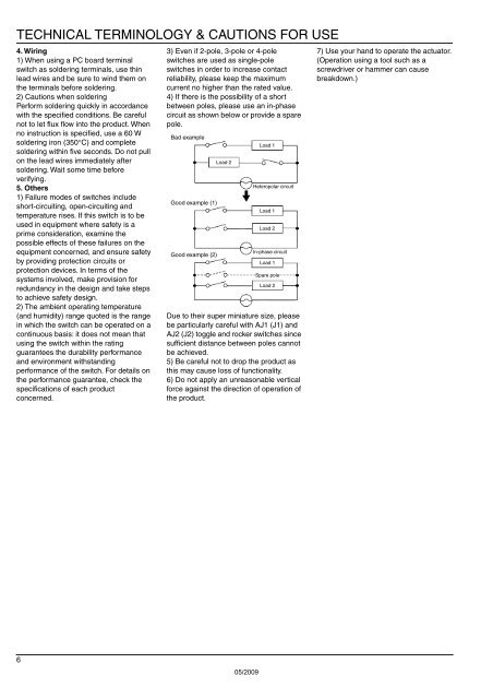
4) If there is the possibility of a short<br />
between poles, please use an in-phase<br />
circuit as shown below or provide a spare<br />
pole.<br />
Bad example<br />
Good example (1)<br />
Good example (2)<br />
Load 2<br />
Load 1<br />
Heteropolar circuit<br />
Load 1<br />
Load 2<br />
In-phase circuit<br />
Load 1<br />
Spare pole<br />
Load 2<br />
Due to their super miniature size, please<br />
be particularly careful with AJ1 (J1) and<br />
AJ2 (J2) toggle and rocker switches since<br />
sufficient distance between poles cannot<br />
be achieved.<br />
5) Be careful not to drop the product as<br />
this may cause loss of functionality.<br />
6) Do not apply an unreasonable vertical<br />
force against the direction of operation of<br />
the product.<br />
7) Use your hand to operate the actuator.<br />
(Operation using a tool such as a<br />
screwdriver or hammer can cause<br />
breakdown.)<br />
6<br />
05/2009