T A B L E O F C O N T E N T S - Panasonic Electric Works Europe AG
T A B L E O F C O N T E N T S - Panasonic Electric Works Europe AG
T A B L E O F C O N T E N T S - Panasonic Electric Works Europe AG

You also want an ePaper? Increase the reach of your titles
YUMPU automatically turns print PDFs into web optimized ePapers that Google loves.
2. Characteristics<br />
Expected life<br />
Mechanical<br />
<strong>Electric</strong>al<br />
Momentary: Min. 50×10 4 , Alternate: Min. 10×10 4 (60 cpm)<br />
Min. 3×10 4 (20 cpm)<br />
Insulation resistance<br />
Min. 100 MΩ (at 500 V DC measured by insulation resistive meter)<br />
Breakdown Between terminals<br />
600 Vrms (at detection current: 10mA)<br />
voltage<br />
Between terminal and ground 1500 Vrms (at detection current: 10mA)<br />
Contact resistance<br />
Max. 100 mΩ (AgNi alloy contact type: by voltage drop at 1 A, 2 to 4 V DC, AgNi alloy and Au<br />
clad contact type: by voltage drop at 0.1 A, 2 to 4 V DC)<br />
Vibration resistance<br />
10 to 55 Hz at double amplitude of 1.5 mm (contact opening: Max. 10 μs)<br />
Shock resistance<br />
Min. 196 m/s 2 (contact opening: Max. 10 μs)<br />
Ambient temperature<br />
–25°C to +85 °C (Not freezing below 0 °C)<br />
Operating force (reference value) Momentary: Approx. 1.96N, Alternate: Approx. 2.45N<br />
Operating stroke (reference value)<br />
Approx. 2.5 mm<br />
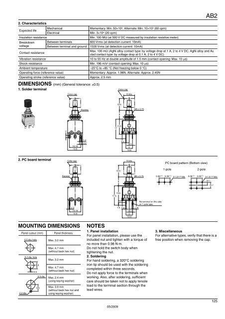
DIMENSIONS (mm) (General tolerance: ±0.5)<br />
1. Solder terminal Color cap<br />
Color cap<br />
10 dia.<br />
AB2<br />
10.6<br />
Keyway<br />
M6 x 0.75<br />
8<br />
17 13.6 0.4<br />
2<br />
10.16<br />
13.5<br />
1.2<br />
2.2<br />
3<br />
6<br />
12.8<br />
2. PC board terminal<br />
Color cap<br />
10 dia.<br />
PC board pattern (Bottom view)<br />
10.6<br />
1-pole<br />
2-pole<br />
Keyway<br />
M6 x 0.75<br />
5.08 ±0.1 5.08 ±0.1 3-1.2±0.05 dia.<br />
3-1.2±0.05<br />
dia.<br />
5.08 ±0.1 5.08 ±0.1 3 ±0.1 6 ±0.1<br />
8<br />
13.6<br />
17.5<br />
No terminal on this side<br />
on 1 pole type.<br />
0.9<br />
10.16<br />
13.5<br />
1.5<br />
0.4<br />
3<br />
6<br />
12.8<br />
1.25<br />
MOUNTING DIMENSIONS<br />
Panel cutout (mm)<br />
2.2 dia.<br />
6.5 dia. hole<br />
6.2 dia. hole<br />
0.6<br />
5.6<br />
6.5 dia.<br />
6.5<br />
Panel thickness<br />
Max. 3.2 mm<br />
Max. 4.7 mm<br />
(without back hex nut)<br />
Max. 3.2 mm<br />
Max. 4.7 mm<br />
(without back hex nut)<br />
Max. 2.4 mm<br />
(using keying washer)<br />
Max. 3.9 mm<br />
(without back hex nut and<br />
using keying washer)<br />
NOTES<br />
1. Panel installation<br />
For panel installation, please use the<br />
included nut and tighten with a torque of<br />
no more than 0.98 N·m.<br />
Do not hold the switch body when<br />
tightening the nut.<br />
2. Soldering<br />
For hand soldering, a 320°C soldering<br />
iron tip should be used with the soldering<br />
completed within three seconds.<br />
Do not apply force to the terminals when<br />
working. Also, after soldering, sufficient<br />
care should be taken not to apply tensile<br />
load to the terminal section through the<br />
lead wires.<br />
05/2009<br />
3. Miscellaneous<br />
For alternative types, verify that there is a<br />
free position when removing the cap.<br />
125