T A B L E O F C O N T E N T S - Panasonic Electric Works Europe AG
T A B L E O F C O N T E N T S - Panasonic Electric Works Europe AG
T A B L E O F C O N T E N T S - Panasonic Electric Works Europe AG

Create successful ePaper yourself
Turn your PDF publications into a flip-book with our unique Google optimized e-Paper software.
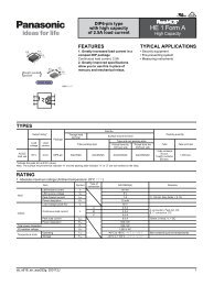
SPECIFICATIONS<br />
1. Contact rating<br />
Type<br />
Voltage<br />
Resistive load<br />
(cos φ ] 1.0)<br />
Remark: The motor load is in accordance with EN61058-1. Inrush current can be switched up to the value of 6 times the indicated rating.<br />
AJ7 (J7)<br />
Motor load (EN61058-1)<br />
(cos φ ] 0.6)<br />
10A type<br />
10A<br />
4A<br />
250V AC<br />
6A type 6A 3A<br />
2. Characteristics<br />
Expected life<br />
Mechanical<br />
Min. 5 × 10 4 (at 20 cpm.)<br />
(Min. operations)<br />
<strong>Electric</strong>al<br />
Min. 10 4 (at 7 cpm., at rated load)<br />
Initial insulation resistance (Between terminals)<br />
Min. 100 MΩ (at 500V DC measured by insulation resistive meter)<br />
Initial breakdown voltage (Between terminals)<br />
2,000 Vrms detection current: 10 mA<br />
Initial contact resistance (By voltage drop at 1A, 2 to 4V DC) Max. 100mΩ<br />
Temperature rise<br />
at 6 × 10 3 ope. or less Max. 30°C (UL1054)<br />
from 6 × 10 3 ope. to 10 4 Max. 55°C (EN61058-1)<br />
Vibration resistance<br />
10 to 55 Hz at double amplitude of 1.5mm<br />
Shock resistance Min. 490m/s 2 {50 G}<br />
Actuator strength<br />
40 N {4.08kgf} for 1 minute (operating direction)<br />
Tensile terminal strength<br />
100 N {10.2kgf} for 1 minute or more (Pull & push direction)<br />
Ambient temperature<br />
–25°C to +85°C (Not freezing below 0°C)<br />
Flame retardancy<br />
UL94V-0<br />
Tracking resistance Min. 175<br />
Operating force<br />
1-pole<br />
2.2 ± 1.2N {0.22 ±0.12kgf}<br />
(reference characteristics) 2-pole<br />
4 ± 2.5N {0.41 ±0.25kgf}<br />
Contact material<br />
AgSnO2 alloy<br />
Remark: Test conditions are in accordance with EN61058-1, UL1054 and JIS C 6571.<br />
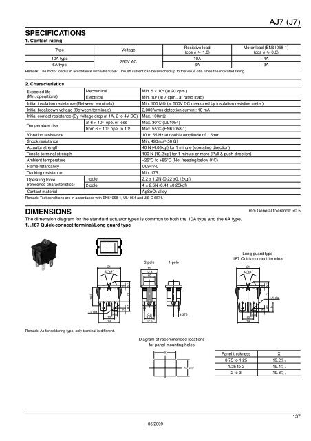
DIMENSIONS<br />
mm General tolerance: ±0.5<br />
The dimension diagram for the standard actuator types is common to both the 10A type and the 6A type.<br />
1. .187 Quick-connect terminal/Long guard type<br />
21<br />
32°±4°<br />
2-pole<br />
15<br />
12.8<br />
10<br />
1-pole<br />
Long guard type<br />
.187 Quick-connect terminal<br />
21<br />
32°±4°<br />
8.5<br />
2<br />
5.3<br />
ON<br />
OFF<br />
16.5<br />
8.5<br />
2<br />
5.3<br />
ON<br />
OFF<br />
13<br />
13<br />
1.4 dia.<br />
9<br />
1.4 dia.<br />
10 4.8<br />
19<br />
3<br />
0.8 4.375<br />
8.75<br />
12.5<br />
10 4.8<br />
19<br />
3<br />
Remark: As for soldering type, only terminal is different.<br />
Diagram of recommended locations<br />
for panel mounting holes<br />
X<br />
12.9 +0.1<br />
−0<br />
Panel thickness<br />
X<br />
0.75 to 1.25 19.2<br />
1.25 to 2 19.4<br />
2 to 3 19.8<br />
+0<br />
−0.1<br />
+0<br />
−0.1<br />
+0<br />
−0.1<br />
05/2009<br />
137