T A B L E O F C O N T E N T S - Panasonic Electric Works Europe AG
T A B L E O F C O N T E N T S - Panasonic Electric Works Europe AG
T A B L E O F C O N T E N T S - Panasonic Electric Works Europe AG

Create successful ePaper yourself
Turn your PDF publications into a flip-book with our unique Google optimized e-Paper software.
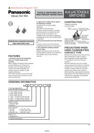
AJ1, AJ2<br />
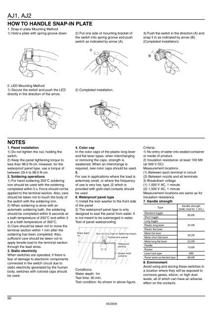
HOW TO HANDLE SNAP-IN PLATE<br />
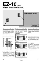
1. Snap-in plate Mounting Method<br />
1) Hold a plate with spring groove down. 2) Put one side of mounting bracket of<br />
the switch into spring groove and push<br />
switch as indicated by arrow (A).<br />
3) Push the switch in the direction (A) and<br />
snap it in as indicated by arrow (B).<br />
(Completed installation)<br />
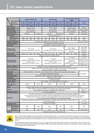
2. LED Mounting Method<br />
1) Secure the switch and push the LED<br />
directly in the direction of the arrow.<br />
2) Completed installation.<br />
NOTES<br />
1. Panel installation<br />
1) Do not tighten the nut, holding the<br />
switch.<br />
2) Keep the panel tightening torque to<br />
less than 98.0 N·cm. However, for the<br />
waterproof panel type, use a torque of<br />
between 29.4 to 98.0 N·cm.<br />
2. Soldering operations<br />
1) For hand soldering 350°C soldering<br />
iron should be used with the soldering<br />
completed within 5 s. Force should not be<br />
applied to the terminal section. Also, care<br />
should be taken not to touch the body of<br />
the switch with the soldering iron.<br />
2) When soldering is done with an<br />
automatic soldering bath, the soldering<br />
should be completed within 6 seconds at<br />
a bath temperature of 250°C and within 3<br />
s at a bath temperature of 350°C.<br />
3) Care should be taken not to move the<br />
terminal section within 1 min after the<br />
soldering has been completed. Also,<br />
sufficient care should be taken not to<br />
apply tensile load to the terminal section<br />
through the lead wires.<br />
3. Static electricity<br />
When switches are operated, if there is<br />
fear of damage to electronic components<br />
connected in the switch circuit due to<br />
static electricity generated by the human<br />
body, switches with colored caps should<br />
be used.<br />
4. Color cap<br />
In the color caps of the plastic long lever<br />
and flat lever types, when interchanging<br />
or removing the caps, strength is<br />
weakened. When an interchange is<br />
required, new color caps should be used.<br />
5.<br />
For use in applications where the load is<br />
extermely small, or where the frequency<br />
of use is very low, type J2 which is<br />
provided with gold clad contacts should<br />
be used.<br />
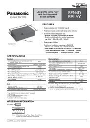
6. Waterproof panel type<br />
1) Install the lock washer to the front side<br />
of the panel.<br />
2) The waterproof panel type is only<br />
designed to seal the panel from water. It<br />
is not meant to be submerged in water.<br />
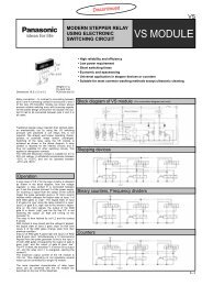
Test of panel waterproofing<br />
Water depth:<br />
1m<br />
Hex nut (2 to 5 kgf·cm tightening torque)<br />
Toothed lock washer<br />
Waterproof<br />
packing<br />
Sealed metal<br />
container<br />
Conditions:<br />
Water depth: 1m<br />
Test time: 30 min.<br />
Test condition: As shown in above figure.<br />
Criteria:<br />
1) No entry of water into sealed container<br />
or inside of product.<br />
2) Insulation resistance: at least 100 M#<br />
(at 500 V DC)<br />
Measurement locations<br />
(1) Between each terminal in circuit<br />
(2) Between nozzle and all terminals<br />
3) Breakdown voltage<br />
(1) 1,000 V AC, 1 minute<br />
(2) 1,500 V AC, 1 minute<br />
Measurement locations are same as for<br />
insulation resistance.<br />
7. Handle strength<br />
Handle strength<br />
Type<br />
(static load for 1 min.)<br />
Standard toggle<br />
68.6N<br />
Short toggle<br />
Long toggle<br />
Plastic long lever<br />
24.5N<br />
Plastic flat lever<br />
Metal flat lever<br />
39.2N<br />
Metal short flat lever<br />
Metal long flat lever 24.5N<br />
Paddle<br />
19.6N<br />
Rocker<br />
Lever lock type<br />
49N<br />
Panel water-protected type 68.6N<br />
8. Environment<br />
Avoid using and storing these switches in<br />
a location where they will be exposed to<br />
corrosive gases, silicon, or high dust<br />
levels, all of which can have an adverse<br />
effect on the contacts.<br />
90<br />
05/2009