T A B L E O F C O N T E N T S - Panasonic Electric Works Europe AG
T A B L E O F C O N T E N T S - Panasonic Electric Works Europe AG
T A B L E O F C O N T E N T S - Panasonic Electric Works Europe AG

Create successful ePaper yourself
Turn your PDF publications into a flip-book with our unique Google optimized e-Paper software.
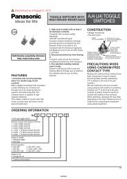
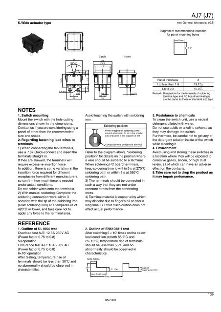
5. Wide actuator type<br />
AJ7 (J7)<br />
mm General tolerance: ±0.5<br />
Diagram of recommended locations<br />
for panel mounting holes<br />
X<br />
21.9 +0.1<br />
0<br />
21<br />
32°±4°<br />
2-pole<br />
24<br />
21.8<br />
19<br />
1-pole<br />
2<br />
5.3<br />
ON<br />
OFF<br />
16.5<br />
1.4 dia.<br />
10 4.8<br />
19<br />
3<br />
13<br />
8.5<br />
0.8 4.375<br />
8.75<br />
21<br />
Panel thickness<br />
X<br />
1 to less than 1.8 19.2<br />
1.8 to 2.3 19.9<br />
+0<br />
−0.1<br />
+0<br />
−0.1<br />
Remark: Dimensions for the terminals of soldering<br />
terminal type and PC board terminal type<br />
are the same as those of standard size type.<br />
NOTES<br />
1. Switch mounting<br />
Mount the switch with the hole cutting<br />
dimensions shown in the dimensions.<br />
Contact us if you are considering using a<br />
panel of other than the recommended<br />
size and shape.<br />
2. Regarding fastening lead wires to<br />
terminals<br />
1) When connecting the tab terminals,<br />
use a .187 Quick-connect and insert the<br />
terminals straight in.<br />
If they are skewed, the terminals will<br />
require excessive insertion force.<br />
In addition, there is some variation in the<br />
insertion force required for different<br />
receptacles from different manufacturers,<br />
so confirm how much force is needed<br />
under actual conditions.<br />
Do not solder wires onto tab terminals.<br />
2) With manual soldering: Complete the<br />
soldering connection work within 3<br />
seconds with the tip of the soldering iron<br />
(60W soldering iron) at a temperature of<br />
420°C or lower, and take care not to<br />
apply any force to the terminal area.<br />
Avoid touching the switch with soldering<br />
iron.<br />
Soldering position<br />
When wrapping or soldering a wire<br />
around a terminal, do so in the shaded<br />
area indicated in the diagram at left.<br />
Contact terminal and ground terminal<br />
Refer to the diagram above, “soldering<br />
position,” for details on the position where<br />
a wire should be soldered to a terminal.<br />
When soldering PC board terminals,<br />
keep soldering time to within 5 s at 270°C<br />
soldering bath or within 3 s at 350°C<br />
soldering bath.<br />
3) The terminals should be connected in<br />
such a way that they are not under<br />
constant stress from the connecting<br />
wires.<br />
4) Terminal material is copper alloy which<br />
may discolor due to finger’s oil or after a<br />
long time. But that discoloration does not<br />
effect actual performance.<br />
3. Resistance to chemicals<br />
To clean the switch unit, use a neutral<br />
detergent diluted with water.<br />
Do not use acidic or alkaline solvents as<br />
they may damage the switch.<br />
Furthermore, be careful not to get any of<br />
the detergent solution inside of the switch<br />
while cleaning it.<br />
4. Environment<br />
Avoid using and storing these switches in<br />
a location where they will be exposed to<br />
corrosive gases, silicon, or high dust<br />
levels, all of which can have an adverse<br />
effect on the contacts.<br />
5. Take care not to drop the product as<br />
it may impair perfomance.<br />
REFERENCE<br />
1. Outline of UL1054 test<br />
Overload test AJ7: 12.5A 250V AC<br />
(Power factor 0.75 to 0.8)<br />
50 operation<br />
Endurance test AJ7: 10A 250V AC<br />
(Power factor 0.75 to 0.8)<br />
6×10 3 operation<br />
After testing, temperature rise of<br />
terminals should be less than 30°C and<br />
no abnormality should be observed in<br />
characteristics.<br />
2. Outline of EN61058-1 test<br />
After switching 5 × 10 3 times on the below<br />
+5<br />
load condition at both 85 0 °C and<br />
25±10°C, temperature rise of terminals<br />
should be less than 55°C and no<br />
abnormality should be observed in<br />
characteristics.<br />
50 to 100ms<br />
24A<br />
2 sec.<br />
4 sec.<br />
J7: 10A<br />
AC: 250V<br />
(Power factor 0.6)<br />
05/2009<br />
139