T A B L E O F C O N T E N T S - Panasonic Electric Works Europe AG
T A B L E O F C O N T E N T S - Panasonic Electric Works Europe AG
T A B L E O F C O N T E N T S - Panasonic Electric Works Europe AG

Create successful ePaper yourself
Turn your PDF publications into a flip-book with our unique Google optimized e-Paper software.
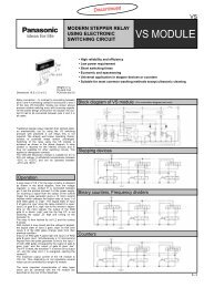
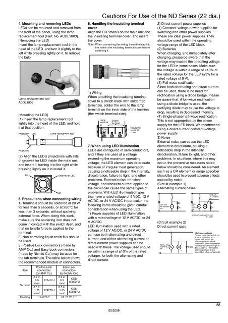
4. Mounting and removing LEDs<br />
LEDs can be mounted and removed from<br />
the front of the panel, using the lamp<br />
replacement tool (Part. No. ACDL1803).<br />
[Removing the LED]<br />
Insert the lamp replacement tool in the<br />
head of the LED, and turn it slightly to the<br />
left while pressing lightly on it, to remove<br />
the bulb.<br />
Lamp replacement tool<br />
ACDL1803<br />
[Mounting the LED]<br />
(1) Insert the lamp replacement tool<br />
lightly into the head of the LED, and hold<br />
it at that position.<br />
Projection<br />
Projection<br />
(2) Align the LED’s projections with slits<br />
of grooves for LED inside the main unit<br />
and insert it, turning it to the right while<br />
pressing lightly on it to install it.<br />
Slit<br />
5. Precautions when connecting wiring<br />
1) Terminals should be soldered at 20 W<br />
for less than 5 seconds, or at 260°C for<br />
less than 3 seconds, without applying<br />
external force. When doing this work,<br />
make sure the soldering iron does not<br />
come in contact with the switch itself, and<br />
that no tensile force is applied to the<br />
terminal.<br />
2) Non-corroding liquid resin flux should<br />
be used.<br />
3) Positive Lock connectors (made by<br />
AMP Co.) and Easy Lock connectors<br />
(made by Nichifu Co.) may be used for<br />
the tab terminals. The table below shows<br />
the recommended models of connectors.<br />
Item<br />
Terminal<br />
LED<br />
Positive Lock<br />
connectors<br />
(by AMP Co.)<br />
0.2 to<br />
0.5 175412-1<br />
mm 2<br />
0.5 to<br />
1.25 174778-1<br />
mm 2<br />
Lamp replacement tool<br />
Grooves for LED<br />
Slit<br />
Easy Lock<br />
connectors<br />
(by Nichifu Co.)<br />
0.2 to<br />
0.3<br />
mm 2<br />
0.5 to<br />
1.25<br />
mm 2<br />
OSS-<br />
62852F3<br />
OSS-<br />
62815F3<br />
Housing 174779-1 NET1-28-1P<br />
Cautions For Use of the ND Series (22 dia.)<br />
6. Handling the insulating terminal<br />
cover<br />
Align the TOP marks on the main unit and<br />
the insulating terminal cover, and insert<br />
the cover.<br />
Note) When connecting the wiring, insert the lead into<br />
the hole in the insulating terminal cover before<br />
soldering it.<br />
1) Wiring<br />
When attaching the insulating terminal<br />
cover to a switch block with solder/tab<br />
terminals, solder the wire to the lamp<br />
terminal on the inner side of the terminal<br />
(the switch terminal side).<br />
Lamp<br />
terminal<br />
Inner<br />
side<br />
Switch<br />
terminal<br />
Insulating<br />
terminal<br />
cover<br />
7. When using LED illumination<br />
LEDs are configured of semiconductors,<br />
and if they are used at a voltage<br />
exceeding the maximum operating<br />
voltage, the LED element can deteriorate<br />
because of irregular heat generation,<br />
causing a noticeable drop in the intensity,<br />
discoloration, failure to light, and other<br />
problems. External noise, transient<br />
voltage, and transient current applied to<br />
the circuit can cause the same types of<br />
problems. With LED illuminated types<br />
that have a rated voltage of 5 VDC, 12 V<br />
AC/DC, or 24 V AC/DC in particular, the<br />
following items should be given careful<br />
consideration when using the LED.<br />
1) Power supplies of LED illumination<br />
with a rated voltage of 12 V AC/DC, or 24<br />
V AC/DC<br />
LED illumination used with a rated<br />
voltage of 12 V AC/DC, or 24 V AC/DC<br />
can use both alternating and direct<br />
current, and either alternating current or<br />
direct current power supplies can be<br />
used with these. The voltage used should<br />
be within a range of ±10% of the rated<br />
voltages for both the alternating and<br />
direct current.<br />
2) Direct current power supplies<br />
(1) Constant-voltage power supplies for<br />
switching and other power supplies<br />
These are ideal power supplies. They<br />
should be used within the operating<br />
voltage range of the LED block.<br />
(2) Batteries<br />
When charging, and immediately after<br />
charging, please be aware that the<br />
voltage may exceed the operating voltage<br />
for the LED in some cases. Make sure<br />
the voltage is within a range of ±10% of<br />
the rated voltage for the LED (±5% for a<br />
rated voltage of 5 V).<br />
(3) Full-wave rectification<br />
Since both alternating and direct current<br />
can be used, there is no need for<br />
rectification using a diode bridge. Please<br />
be aware that, if full-wave rectification<br />
using a diode bridge is used, the<br />
rectifying diode may cause the voltage to<br />
drop, resulting in decreased intensity.<br />
(4) Single-phase half-wave rectification<br />
This is not appropriate as the power<br />
supply for the LED block. We recommend<br />
using a direct current constant-voltage<br />
power supply.<br />
3) Noise<br />
External noise can cause the LED<br />
element to deteriorate, causing a<br />
noticeable drop in the intensity,<br />
discoloration, failure to light, and other<br />
problems. In situations where this may<br />
occur, the preventive measures noted<br />
below should be considered. An element<br />
such as a CR element or surge absorber<br />
should be used to prevent adverse effects<br />
caused by noise.<br />
(Circuit example 1)<br />
Alternating current cases<br />
LED with<br />
AC adapter,<br />
etc.<br />
(Circuit example 2)<br />
Direct current case<br />
Relay, coil,<br />
solenoid,<br />
etc.<br />
LED<br />
Ry<br />
C<br />
R<br />
LED<br />
Diode<br />
Relay,<br />
coil,<br />
solenoid,<br />
etc.<br />
Ry<br />
LED<br />
LED with<br />
AC adapter,<br />
etc.<br />
C<br />
R<br />
(Reference value) C: 0.1μF<br />
R: 120Ω<br />
(Reference values)<br />
Current capacitance of diode:<br />
A value equivalent to or<br />
higher than that of the<br />
operating current for the<br />
solenoid or other components<br />
Reverse dielectric strength of<br />
diode: Approx. 10 times the<br />
operating voltage of the<br />
solenoid or other components<br />
05/2009<br />
55