T A B L E O F C O N T E N T S - Panasonic Electric Works Europe AG
T A B L E O F C O N T E N T S - Panasonic Electric Works Europe AG
T A B L E O F C O N T E N T S - Panasonic Electric Works Europe AG

You also want an ePaper? Increase the reach of your titles
YUMPU automatically turns print PDFs into web optimized ePapers that Google loves.
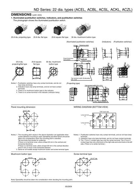
ND Series: 22 dia. types (ACEL, ACBL, ACSL, ACKL, ACZL)<br />
DIMENSIONS (unit: mm)<br />
1. Illuminated pushbutton switches, indicators, and pushbutton switches<br />
The photograph shows the illuminated pushbutton switch.<br />
25.8 dia. projecting type 25.8 dia. flat type 25.8 square flat type 30 dia. mushroom button type<br />
(Illuminated pushbutton switches) (Indicators) (Pushbutton switches)<br />
0.5<br />
Retaining plate<br />
LOCK<br />
TO<br />
P<br />
4.85<br />
6.8<br />
11.35<br />
1.95<br />
6.8<br />
25.8 dia.<br />
projecting/flat type<br />
25.8 square<br />
flat type<br />
30 dia. mushroom<br />
button type<br />
Panel thickness:<br />
0.8 to 6mm<br />
9<br />
Lock nut<br />
Rubber washer<br />
36 9<br />
11.7 8.5<br />
6.5<br />
6.8<br />
R18<br />
R18<br />
6.8<br />
LOCK<br />
LOCK<br />
25.8 dia.<br />
25.8<br />
30 dia.<br />
Tab terminal width (Solderable):<br />
2.8 × 0.5t<br />
1.2<br />
6 6<br />
18.2<br />
16.2<br />
25<br />
26.2<br />
23.2<br />
25.4<br />
Notes) 1. Pushbutton switches have only contact terminals, and do not<br />
have lamp terminals.<br />
2. Indicators have only lamp terminals, and do not have contact<br />
terminals.<br />
3. There is no mushroom button type in the indicator.<br />
4. There is no screw terminal in the indicator (indicator lamp).<br />
(Projecting type)<br />
9<br />
13.1<br />
Tab terminal width 2.8 × 0.5 t<br />
17<br />
9 11.7 8.5<br />
2.6<br />
1.2<br />
11.2<br />
36 9<br />
Lot No. display position<br />
6 6<br />
16.2<br />
R18<br />
25<br />
26.2<br />
LOCK<br />
Panel mounting dimension<br />
22.3 +0.4<br />
0 dia.<br />
WIRING DI<strong>AG</strong>RAM (BOTTOM VIEW)<br />
TOP mark side<br />
26<br />
∗<br />
Lamp terminal<br />
(+)<br />
Lamp terminal<br />
(−)<br />
X2 X2 X1<br />
C NO NC<br />
C NO NC<br />
C NO NC<br />
26<br />
∗<br />
Notes) 1. The mounting pitch values in the above illustration are applicable when<br />
cluster adhesion mounting is used. Operability and other factors should be<br />
taken into consideration when the mounting pitch is decided.<br />
Tab terminals that double for soldering:<br />
If there is no terminal cover, allow at least 26 mm in the vertical and<br />
horizontal directions.<br />
If there is a terminal cover, allow at least 26 mm in the vertical direction<br />
and 27 mm or more in the horizontal direction.<br />
2. Same for all models except mushroom button and screw terminal types.<br />
Mushroom button type<br />
Notes) 1. Pushbutton switches have only contact terminals, and do not have lamp<br />
terminals.<br />
2. Indicators have only lamp terminals, and do not have contact terminals.<br />
3. The 1 Form C contact type has only the center terminal. The 2 Form C<br />
contact type has only a terminal on the right side and a terminal on the left<br />
side. (There is no center terminal.)<br />
Screw terminal type<br />
35 min.<br />
22.3 +0.4<br />
–0 dia.<br />
26<br />
22.3 +0.4<br />
–0 dia.<br />
35 min.<br />
40<br />
Note) Operability should be taken into consideration when deciding the mounting pitch.<br />
49<br />
05/2009