T A B L E O F C O N T E N T S - Panasonic Electric Works Europe AG
T A B L E O F C O N T E N T S - Panasonic Electric Works Europe AG
T A B L E O F C O N T E N T S - Panasonic Electric Works Europe AG

Create successful ePaper yourself
Turn your PDF publications into a flip-book with our unique Google optimized e-Paper software.
Cautions For Use of the NS Series<br />
Cautions For Use of the NS Series<br />
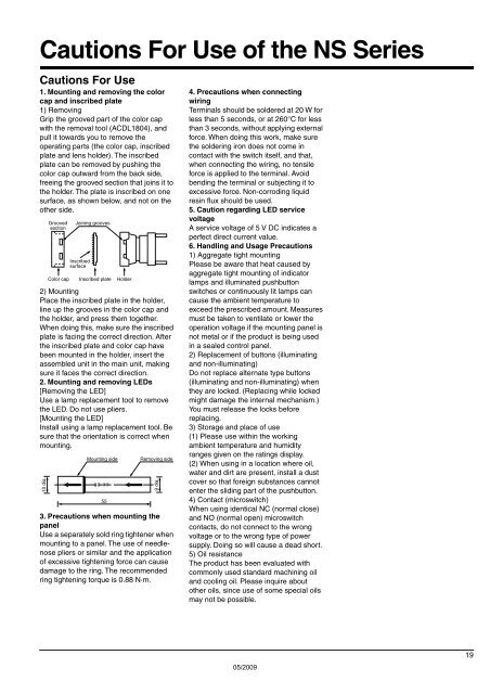
Cautions For Use<br />
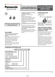
1. Mounting and removing the color<br />
cap and inscribed plate<br />
1) Removing<br />
Grip the grooved part of the color cap<br />
with the removal tool (ACDL1804), and<br />
pull it towards you to remove the<br />
operating parts (the color cap, inscribed<br />
plate and lens holder). The inscribed<br />
plate can be removed by pushing the<br />
color cap outward from the back side,<br />
freeing the grooved section that joins it to<br />
the holder. The plate is inscribed on one<br />
surface, as shown below, and not on the<br />
other side.<br />
2) Mounting<br />
Place the inscribed plate in the holder,<br />
line up the grooves in the color cap and<br />
the holder, and press them together.<br />
When doing this, make sure the inscribed<br />
plate is facing the correct direction. After<br />
the inscribed plate and color cap have<br />
been mounted in the holder, insert the<br />
assembled unit in the main unit, making<br />
sure it faces the correct direction.<br />
2. Mounting and removing LEDs<br />
[Removing the LED]<br />
Use a lamp replacement tool to remove<br />
the LED. Do not use pliers.<br />
[Mounting the LED]<br />
Install using a lamp replacement tool. Be<br />
sure that the orientation is correct when<br />
mounting.<br />
10 dia.<br />
Grooved<br />
section<br />
Joining grooves<br />
Inscribed<br />
surface<br />
Color cap Inscribed plate Holder<br />
Mounting side<br />
55<br />
Removing side<br />
9 dia.<br />
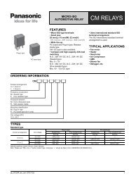
3. Precautions when mounting the<br />
panel<br />
Use a separately sold ring tightener when<br />
mounting to a panel. The use of needlenose<br />
pliers or similar and the application<br />
of excessive tightening force can cause<br />
damage to the ring. The recommended<br />
ring tightening torque is 0.88 N·m.<br />
4. Precautions when connecting<br />
wiring<br />
Terminals should be soldered at 20 W for<br />
less than 5 seconds, or at 260°C for less<br />
than 3 seconds, without applying external<br />
force. When doing this work, make sure<br />
the soldering iron does not come in<br />
contact with the switch itself, and that,<br />
when connecting the wiring, no tensile<br />
force is applied to the terminal. Avoid<br />
bending the terminal or subjecting it to<br />
excessive force. Non-corroding liquid<br />
resin flux should be used.<br />
5. Caution regarding LED service<br />
voltage<br />
A service voltage of 5 V DC indicates a<br />
perfect direct current value.<br />
6. Handling and Usage Precautions<br />
1) Aggregate tight mounting<br />
Please be aware that heat caused by<br />
aggregate tight mounting of indicator<br />
lamps and illuminated pushbutton<br />
switches or continuously lit lamps can<br />
cause the ambient temperature to<br />
exceed the prescribed amount. Measures<br />
must be taken to ventilate or lower the<br />
operation voltage if the mounting panel is<br />
not metal or if the product is being used<br />
in a sealed control panel.<br />
2) Replacement of buttons (illuminating<br />
and non-illuminating)<br />
Do not replace alternate type buttons<br />
(illuminating and non-illuminating) when<br />
they are locked. (Replacing while locked<br />
might damage the internal mechanism.)<br />
You must release the locks before<br />
replacing.<br />
3) Storage and place of use<br />
(1) Please use within the working<br />
ambient temperature and humidity<br />
ranges given on the ratings display.<br />
(2) When using in a location where oil,<br />
water and dirt are present, install a dust<br />
cover so that foreign substances cannot<br />
enter the sliding part of the pushbutton.<br />
4) Contact (microswitch)<br />
When using identical NC (normal close)<br />
and NO (normal open) microswitch<br />
contacts, do not connect to the wrong<br />
voltage or to the wrong type of power<br />
supply. Doing so will cause a dead short.<br />
5) Oil resistance<br />
The product has been evaluated with<br />
commonly used standard machining oil<br />
and cooling oil. Please inquire about<br />
other oils, since use of some special oils<br />
may not be possible.<br />
05/2009<br />
19