T A B L E O F C O N T E N T S - Panasonic Electric Works Europe AG
T A B L E O F C O N T E N T S - Panasonic Electric Works Europe AG
T A B L E O F C O N T E N T S - Panasonic Electric Works Europe AG

You also want an ePaper? Increase the reach of your titles
YUMPU automatically turns print PDFs into web optimized ePapers that Google loves.
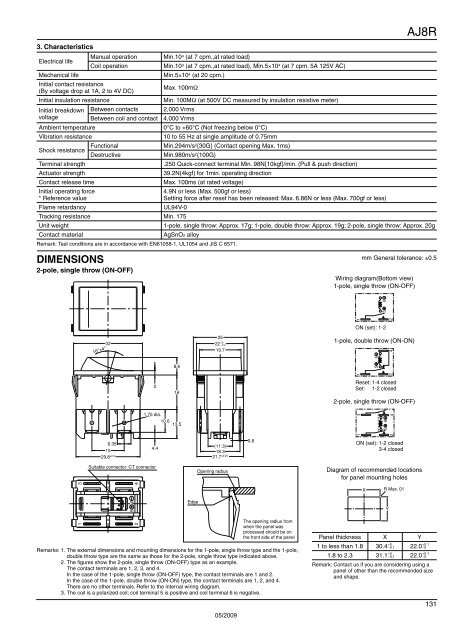
3. Characteristics<br />
<strong>Electric</strong>al life<br />
Mechanical life<br />
Manual operation<br />
Coil operation<br />
Initial contact resistance<br />
(By voltage drop at 1A, 2 to 4V DC)<br />
Initial insulation resistance<br />
Initial breakdown Between contacts<br />
voltage<br />
Between coil and contact<br />
Ambient temperature<br />
Vibration resistance<br />
Min.10 4 (at 7 cpm.,at rated load)<br />
Remark: Test conditions are in accordance with EN61058-1, UL1054 and JIS C 6571.<br />
Min.10 3 (at 7 cpm.,at rated load), Min.5×10 4 (at 7 cpm. 5A 125V AC)<br />
Min.5×10 4 (at 20 cpm.)<br />
Max. 100mΩ<br />
Min. 100MΩ (at 500V DC measured by insulation resistive meter)<br />
2,000 Vrms<br />
4,000 Vrms<br />
0°C to +60°C (Not freezing below 0°C)<br />
10 to 55 Hz at single amplitude of 0.75mm<br />
Shock resistance Functional Min.294m/s2 {30G} (Contact opening Max. 1ms)<br />
Destructive<br />
Min.980m/s 2 {100G}<br />
Terminal strength<br />
.250 Quick-connect terminal Min. 98N{10kgf}/min. (Pull & push direction)<br />
Actuator strength<br />
39.2N{4kgf} for 1min. operating direction<br />
Contact release time<br />
Max. 100ms (at rated voltage)<br />
Initial operating force<br />
* Reference value<br />
Flame retardancy<br />
4.9N or less (Max. 500gf or less)<br />
Setting force after reset has been released: Max. 6.86N or less (Max. 700gf or less)<br />
UL94V-0<br />
AJ8R<br />
Tracking resistance Min. 175<br />
Unit weight<br />
1-pole, single throw: Approx. 17g; 1-pole, double throw: Approx. 19g; 2-pole, single throw: Approx. 20g<br />
Contact material<br />
AgSnO2 alloy<br />
DIMENSIONS<br />
mm General tolerance: ±0.5<br />
2-pole, single throw (ON-OFF)<br />
Wiring diagram(Bottom view)<br />
1-pole, single throw (ON-OFF)<br />
1<br />
2<br />
5 6<br />
ON (set): 1-2<br />
16°±4°<br />
32<br />
8.6<br />
25<br />
22 +0<br />
−0.2<br />
19.7<br />
1-pole, double throw (ON-ON)<br />
1<br />
5 6<br />
2 4<br />
2<br />
16<br />
Reset: 1-4 closed<br />
Set: 1-2 closed<br />
2-pole, single throw (ON-OFF)<br />
1.75 dia.<br />
10.6<br />
13.5<br />
1 3<br />
5 6<br />
4<br />
2<br />
6.35<br />
15<br />
29.8 ±0.3<br />
4.4<br />
(11.3)<br />
18.3<br />
21.7 ±0.25<br />
0.8<br />
ON (set): 1-2 closed<br />
3-4 closed<br />
1 3<br />
Suitable connector: CT connector<br />
5 6<br />
2 4<br />
Edge<br />
Opening radius<br />
The opening radius from<br />
when the panel was<br />
processed should be on<br />
the front side of the panel<br />
Remarks: 1. The external dimensions and mounting dimensions for the 1-pole, single throw type and the 1-pole,<br />
double throw type are the same as those for the 2-pole, single throw type indicated above.<br />
2. The figures show the 2-pole, single throw (ON-OFF) type as an example.<br />
The contact terminals are 1, 2, 3, and 4.<br />
In the case of the 1-pole, single throw (ON-OFF) type, the contact terminals are 1 and 2.<br />
In the case of the 1-pole, double throw (ON-ON) type, the contact terminals are 1, 2, and 4.<br />
There are no other terminals. Refer to the internal wiring diagram.<br />
3. The coil is a polarized coil; coil terminal 5 is positive and coil terminal 6 is negative.<br />
05/2009<br />
Diagram of recommended locations<br />
for panel mounting holes<br />
X<br />
R Max. 01<br />
Panel thickness X Y<br />
1 to less than 1.8<br />
+0<br />
30.4−0.1<br />
+0.1<br />
22.0 −0<br />
1.8 to 2.3<br />
+0<br />
31.1−0.1<br />
+0.1<br />
22.0−0<br />
Remark: Contact us if you are considering using a<br />
panel of other than the recommended size<br />
and shape.<br />
Y<br />
131