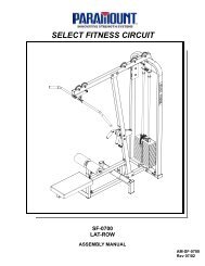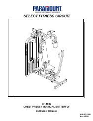
XFT-100A - Paramount Fitness
XFT-100A - Paramount Fitness
XFT-100A - Paramount Fitness

You also want an ePaper? Increase the reach of your titles
YUMPU automatically turns print PDFs into web optimized ePapers that Google loves.
<strong>XFT</strong>-<strong>100A</strong><br />
FUNCTIONAL TRAINER<br />
ASSEMBLY MANUAL<br />
AM-<strong>XFT</strong>-100<br />
REV. 012813
A MESSAGE TO OUR CUSTOMERS<br />
Thank you for your purchase of the <strong>Paramount</strong> <strong>Fitness</strong> <strong>XFT</strong>-100 Functional Trainer. Because of the<br />
many unique features included in this machine, this manual was created to provide you with<br />
information on how to properly install and maintain your equipment. Proper maintenance will<br />
ensure that your new equipment will last for years.<br />
For your convenience, product questions can be answered by an Authorized <strong>Paramount</strong> Dealer or<br />
by contacting a <strong>Paramount</strong> Customer Service Representative at:<br />
1-800-721-2121 or 1-323-721-2121<br />
Office hours are Monday-Friday, 7:30 am - 4:30 pm PST<br />
Or email us at nasales@paramountfitness.com<br />
Thank You for your patronage.<br />
<strong>Paramount</strong> <strong>Fitness</strong> Corporation<br />
6450 East Bandini Blvd.<br />
Los Angeles, CA 90040<br />
IMPORTANT<br />
SERIOUS INJURIES TO USERS, BYSTANDERS OR INSTALLERS CAN OCCUR IF THE<br />
INSTRUCTIONS AND WARNINGS CONTAINED IN THIS MANUAL ARE NOT FOLLOWED. TO<br />
MINIMIZE THIS RISK, READ THE MANUAL BEFORE BEGINNING THE INSTALLATION TO<br />
FAMILIARIZE YOURSELF WITH ITS CONTENTS AND THEN BE CERTAIN TO FOLLOW EACH<br />
OF THE STEPS AND PRACTICES DESCRIBED. IN ADDITION, REVIEW THE GENERAL<br />
MAINTENANCE MANUAL, FACILITY SIGN AND OTHER DOCUMENTS THAT MAY<br />
ACCOMPANY EACH MACHINE, FOR IMPORTANT SAFETY AND MAINTENANCE TIPS. THE<br />
MANUAL HAS BEEN INCLUDED WITH YOUR MACHINE ORDER AND CAN ALSO BE<br />
DOWNLOADED FROM OUR WEBSITE AT: http://www.paramountfitness.com<br />
PLEASE RETAIN THIS MANUAL FOR FUTURE REFERENCE.<br />
2
TABLE OF CONTENTS<br />
SAFETY.......................................................................................................................................... 4<br />
GENERAL CARE AND MAINTENANCE................................................................................................. 7<br />
MACHINE SPECIFICATIONS.............................................................................................................. 8<br />
PREPARATION................................................................................................................................ 9<br />
CARTON CONTENTS........................................................................................................................ 10<br />
STEP 1: ASSEMBLE THE ADJUSTMENT DISCS.................................................................................... 12<br />
STEP 2: ASSEMBLE THE FOOT EXTENSIONS....................................................................................... 13<br />
STEP 3: ASSEMBLE THE CROSS BRACES........................................................................................... 14<br />
STEP 4: ASSEMBLE THE WEIGHT PLATES.......................................................................................... 15<br />
STEP 5: ATTACH THE WEIGHT STACK LABELS.................................................................................... 16<br />
CABLE ROUTING DIAGRAM.............................................................................................................. 17<br />
MACHINE LABELS........................................................................................................................... 18<br />
SERVICE........................................................................................................................................ 19<br />
PARTS DIAGRAMS.......................................................................................................................... 20<br />
PARAMOUNT LIMITED WARRANTY................................................................................................... 30<br />
3
SAFETY<br />
FACILITY AND USER SAFETY PRECAUTIONS<br />
1. Review and understand all of the warning labels affixed to this machine and on the facility<br />
safety sign.<br />
2. Be certain that the machine operation is understood before it is used. Refer to the<br />
instructional Procedure Label affixed to the machine.<br />
3. Make sure all users are properly trained on how to use this equipment. If this machine is<br />
being used in a commercial setting, end users may not have access to this Owners Manual. It<br />
is the responsibility of the facility to instruct users as to the proper usage of the equipment as<br />
well as making them aware of potential hazards. Maximum user weight is 300 lbs (136 kg).<br />
4. Use each machine only for the intended exercise. Do not allow anyone to invent exercises not<br />
included on the Instructional Procedure Label or the Intended Use Label.<br />
5. Do not modify the machine.<br />
6. This equipment meets industry safety standards for stability when used for the intended<br />
exercise. Do not allow straps, resistance bands or other means to be attached to the<br />
framework of this machine to perform stretching or body weight exercises. This can result in<br />
machine instability and lead to serious crushing injuries.<br />
7. Keep children away from this equipment. Adults should closely supervise use by teenagers.<br />
8. It is recommended that users receive a thorough medical exam before commencing an<br />
exercise program. All medical issues should be reviewed to ensure that weight training will<br />
not aggravate pre-existing medical conditions.<br />
9. If the machine appears damaged or inoperable, contact a facility staff member to place an<br />
“OUT OF ORDER, DO NOT USE” sign on the machine until it is repaired. Only use <strong>Paramount</strong><br />
supplied replacement components to service this machine.<br />
10. Instruct users not to wear loose or dangling clothes or have headphone wires hanging when<br />
using this equipment.<br />
11. Do not attempt to free any jammed assemblies by yourself as this may cause injury.<br />
12. On Plate Loaded and Free Weight machines:<br />
12a. Use of spotter(s). Instruct users to seek the advice of the facility staff as to the<br />
appropriate use of spotters when lifting. More then one spotter may be required<br />
depending upon the amount of weight being lifted.<br />
12b. Instruct users to load weight plates evenly and carefully (one side and then the other)<br />
to avoid tipping equipment and crushing injuries.<br />
12c. If the machine is equipped with safety stops or catches, inspect them and verify their<br />
proper operation before use and make sure they are securely in place before using or<br />
exiting the machine. Be certain members are instructed on how to operate and adjust<br />
all safety mechanisms.<br />
4
SAFETY<br />
12d. This equipment is designed for standard olympic size weight plates with a 50mm bore<br />
(1.9”).<br />
12e. Do not exceed the maximum weight capacity of the machine. Maximum plate size is<br />
45 lbs. (25 kg.).<br />
13. On Selectorized and Cable equipped machines:<br />
13a. Do not allow users to perform any exercise by holding the end of the cable and/or the<br />
cable end fitting. Use only appropriate handles or attachments properly connected to<br />
the cable end.<br />
13b. Do not high-pin or double-pin the weight stack. Do not allow the machine to be used if<br />
the top plate or weight stack is pinned in a raised position. Use an assistant and<br />
carefully return the machine to the proper position with the cap plate resting on the top<br />
weight. Inspect the entire length of the cable to ensure that it is properly seated in all<br />
of the pulley grooves.<br />
13c. Do not allow the use of weight plates or dumbbells to be used as a means to add<br />
additional weight to the weight stacks. Use only the <strong>Paramount</strong> adder weight system<br />
specifically designed for the machine.<br />
INSTALLATION SAFETY PRECAUTIONS<br />
1. Read this Installation Manual entirely before assembling this equipment.<br />
2. Verify that there is adequate space surrounding this piece of equipment for safe access and<br />
operation. Installation must meet ADA requirements for accessibility.<br />
3. Install this piece of equipment on a solid level surface that does not deviate more then 1/8”<br />
over a 10’ distance (or as defined and required by local building and architectural codes.<br />
4. <strong>Paramount</strong> strongly recommends that all equipment be anchored to the floor to prevent<br />
movement and increase stability.<br />
• Due to the wide variation of flooring on which the unit can be installed, contact a<br />
qualified contractor to determine an appropriate fastening system for your floor.<br />
• Use 3/8” diameter hardware (10 mm) to anchor the machine. Anchors should have a<br />
minimum pull out force of 220 lbs (110 kgs) for each position.<br />
• When attaching the machine to the floor, if there is a gap between the machine foot<br />
and the floor, do not use the anchor to remove the gap as this can cause the<br />
machine frame to deform. Instead, place a shim between the bottom of the foot and<br />
the floor, then tighten the anchor.<br />
• Anchoring holes are provided on the feet of the frame. All anchoring locations must<br />
be used when anchoring the equipment to the floor.<br />
5. DO NOT install any fitness equipment near a pool, hot tub or other damp locations. Corrosion<br />
caused by installation in these locations can lead to premature failure of components.<br />
6. Be sure all hardware is tight before using this machine.<br />
5
SAFETY<br />
MAINTENANCE SAFETY PRECAUTIONS<br />
1. Refer to Maintenance Schedule label on the machine as well as this manual for when to<br />
perform maintenance.<br />
2. Check the function of your machine DAILY by verifying the following:<br />
• Inspect cables and end fittings for any signs of wear. Replace if worn, frayed or<br />
damaged with original <strong>Paramount</strong> replacement components.<br />
• Verify that all adjustments are possible and carried out with ease. Make sure that<br />
each adjustment pin inserts completely into each position without binding.<br />
• Verify that safety catches and stops are in proper working order and engaged.<br />
• Verify that the exercise is performed smoothly, free of noise and/or binding.<br />
• If equipped with a weight stack, verify that the proper weight selector pin is in place.<br />
3. Check the function of your machine WEEKLY by verifying the following:<br />
• Nuts, Bolts, and Fasteners: Check tightness weekly. If any hardware has become<br />
loose, retighten and/or use Loctite Threadlocker 242.<br />
• Frames and Lifting Arms: Inspect weekly for integrity and function. Replace any<br />
component at first signs of wear. Use only <strong>Paramount</strong> supplied components.<br />
4. Replace any warning label at first sign of wear. Labels and the Facility Safety Sign may be<br />
obtained from <strong>Paramount</strong> free of charge.<br />
BOLT LENGTH MEASURING GUIDE<br />
FLAT HEAD SCREW<br />
BUTTON HEAD SCREW<br />
HEX HEAD SCREW<br />
SOCKET HEAD SCREW<br />
1 2 3 4 5<br />
6
GENERAL CARE AND MAINTENANCE<br />
IMPORTANT<br />
Preventative maintenance is crucial to maintaining the function and safety of this equipment. Your<br />
facility must establish written guidelines for preventative maintenance and keep written or online<br />
records of the maintenance performed on these products. As a minimum, the items presented in<br />
the SAFETY section of this document and the items that follow here, should be included in your<br />
maintenance program.<br />
1. Cables: Inspect end fittings daily for wear. Inspect the entire length of the cable weekly.<br />
Replace cables at the first sign of wear and on an annual basis. If the cable tension has<br />
been adjusted, be certain that the cable nut is tight.<br />
2. Nuts, Bolts, and Fasteners: Check tightness weekly. If any hardware has become loose,<br />
retighten and/or use Loctite TM brand Threadlocker 242. Be sure all hardware is tight<br />
before using the machine.<br />
3. Safety Catches: Inspect catches, stop rods and their associated fasteners weekly. Tighten<br />
any loose hardware and replace any components at first signs of wear.<br />
4. Frames: Wipe all machines down with a damp cloth and dry completely each day. This<br />
includes painted parts, chrome parts and upholstered pads.<br />
5. Painted and chrome plated parts: Use Simple Green or similar cleaner for light dirt and<br />
grime. Use Turtle Wax Polishing Compound or a good car polish to remove heavier dirt<br />
and grease as well as for polishing. DO NOT use solvents, lacquer thinner, acetone or<br />
finger nail polish remover. For scuffs and marks that are not removed by the above<br />
methods use a soft scrub cleanser. Make sure all parts are dry upon completion.<br />
6. Weight stack enclosures (shrouds): Wipe down with a damp cloth as needed.<br />
7. Exercise instruction labels: Clean with soap and water as needed.<br />
8. Guide rods: Wipe all dirt and dust from the guide rods before applying a light application<br />
of Tri-Flow TM or other teflon spray lubricant. Spray the Tri-Flow TM on a rag and then wipe<br />
the guide rods with the rag. DO NOT use oil lubricants such as WD-40. Caution: Tri-Flow TM<br />
will stain carpet and clothing.<br />
9. Bronze bushings: Check monthly for signs of wear and replace as needed.<br />
10. Linear Bearing Shafts: Wipe any accumulation of dust or other contaminants from the<br />
shafts on a weekly basis. Apply a thin layer of a Teflon® (PTFE) grease on a weekly basis.<br />
<strong>Paramount</strong> recommends Magnalube® brand.<br />
11. When replacing any component, use only <strong>Paramount</strong> supplied parts.<br />
12. Please refer to the General Maintenance Manual (part number: AM-GMM) for other<br />
important safety and maintenance information.<br />
13. Be sure all hardware is tight before using the machine.<br />
Retain these instructions for future reference.<br />
If you have any questions, do not hesitate to contact your <strong>Paramount</strong> dealer or <strong>Paramount</strong> <strong>Fitness</strong><br />
Corp. at (800)721-2121 or nasales@paramountfitness.com.<br />
7
MACHINE SPECIFICATIONS<br />
F EATURES<br />
• Two 130lb. [59 kg.] fully independent weight stacks.<br />
• The cable/pulley arrangement on this machine provides a 2:1 weight reduction. This<br />
means that the handle pull force required to raise the entire 130 lb. weight stack is<br />
actually 65 lb. The advantage of this for functional training is that the weight stack has<br />
1/2 the momentum and 2 times the cable travel of a conventional 1:1 ratio machine.<br />
• (12) weight stack settings. Pull force increments are 5.0lbs [2.3 kg].<br />
• 65 lb. [29.5 kg.] max resistance at cable end (per handle).<br />
• Cable travel is 6.4 feet (77 inches)[194 cm.] per handle.<br />
• Machine weight = 553 lbs. [251 kg.]<br />
• Floor loading = 44 lbs/ft 2 [211 kg/m 2 ]<br />
• 20 vertical arm adjustments labeled “A” through “T”.<br />
• 14 horizontal arm adjustments labeled “1” through “14”<br />
• MAXIMUM user weight = 300 lbs. (136 kg.)<br />
<br />
<br />
<br />
<br />
<br />
<br />
<br />
<br />
<br />
<br />
<br />
<br />
<br />
<br />
*<br />
<br />
<br />
*Max height shown with standard chin-up bar. For low ceiling applications (under 84”),<br />
order optional cross brace <strong>XFT</strong>100-CBR200ALT to replace chin-up bar.<br />
8
PREPARATION<br />
REQUIRED TOOLS<br />
Ratchet Handle<br />
Socket Extension, (8” or longer)<br />
note: 2 or more shorter extensions may be used to<br />
achieve the necessary length for assembly.<br />
Hex Bit Sockets<br />
- 7/32” (or 5.5mm)<br />
- 5/16” (or 8mm)<br />
or<br />
9/16” Socket or 9/16” wrench<br />
Allen wrench (supplied with unit):<br />
- 1/8”<br />
- 7/32” (or 5.5 mm)<br />
Plastic or Rubber Mallet<br />
Step ladder (highly recommended)<br />
CARTONS REQUIREMENTS<br />
Your <strong>XFT</strong>-100 is shipped partially assembled in 2 main cartons. Carton 1 contains the right side<br />
frame and Carton 2 contains the left side frame.<br />
Each machine requires (6) boxes of weight plates, (3) boxes per weight stack. Each box contains<br />
four 10 lb. weight plates.<br />
LEFT SIDE<br />
10 LB. Weight Plate Box<br />
RIGHT SIDE<br />
Part Number: B1602 Comprised<br />
of<br />
(4) x 10 lb. Weight Plates<br />
It is strongly recommended that at least two people are used to assemble this machine.<br />
9
CARTON CONTENTS<br />
CARTON 1 (<strong>XFT</strong><strong>100A</strong>-CTN1)<br />
ITEM PART NUMBER DESCRIPTION QTY.<br />
1 <strong>XFT</strong>100-HFA500X FRAME ASSEMBLY, RIGHT SIDE 1<br />
1<br />
2 <strong>XFT</strong>100-CBR000X CROSS BRACE, LOWER 1<br />
3 <strong>XFT</strong>100-CBR100X CROSS BRACE, UPPER 1<br />
4 <strong>XFT</strong>100-MFR200X FOOT EXTENSION, RIGHT SIDE 1<br />
5 <strong>XFT</strong>100-ADJ000X ADJUSTMENT DISC, RIGHT 1<br />
6 <strong>XFT</strong>100-HW HARDWARE BOX 1<br />
5<br />
3<br />
2 6<br />
4<br />
2<br />
CARTON 2 (<strong>XFT</strong><strong>100A</strong>-CTN2)<br />
ITEM PART NUMBER DESCRIPTION QTY.<br />
1 <strong>XFT</strong>100-HFA600X FRAME ASSEMBLY, LEFT SIDE 1<br />
2 <strong>XFT</strong>100-CBR200 CHIN UP BAR 1<br />
3 <strong>XFT</strong>100-MFR300X FOOT EXTENSION, LEFT SIDE 1<br />
4 <strong>XFT</strong>100-ADJ100X ADJUSTMENT DISC, LEFT 1<br />
1<br />
4<br />
3<br />
10
CARTON CONTENTS<br />
H ARDWARE BOX CONTENTS (<strong>XFT</strong>100-HW)<br />
PART NUMBER DESCRIPTION QTY.<br />
C 624 Socket Head Screw, 3/8”-16 x 1-1/4” 4<br />
C 657ZP Flat Head Screw, 3/8”-16 x 3/4”, ZINC 8<br />
C 659ZP Flat Head Screw, 3/8”-16 x 1-1/4”, ZINC 4<br />
C 678ZP Button Head Screw, 3/8”-16 x 1”, ZINC 8<br />
C 749 Split Lock Washer, 3/8” 12<br />
C 754C Flat Washer, 3/8” 16<br />
C 766A Lock Nut, 3/8-16, low height 8<br />
IT90013800 End Plug, 50 x 100 Oval 2<br />
LBL-WSEM-01065<br />
Label, Weight Stack, 12 position, 65 lbs<br />
with 29.5 kg.<br />
2<br />
B1005 Carabiner, snap link 2<br />
B1110A Strap Handle, molded with logo 2<br />
OPTIONAL ACCESSORY KIT<br />
An optional accessory kit is available for your <strong>XFT</strong>-100 Functional Trainer, part #<strong>XFT</strong>-100-ACC-KIT.<br />
An assortment of handles and cable attachments are included to allow users to perform more<br />
diverse exercises and target specific muscles and movements more completely.<br />
OPTIONAL ADDER WEIGHT KIT<br />
An optional adder weight kit is available for this machine. The kit contains (2) 5 lb. adder weights,<br />
each of which will provide 2.5 lbs. of resistance at the handle. Part number is <strong>XFT</strong>-100-ADR.<br />
11
STEP 1: ASSEMBLE ADJUSTMENT DISCS<br />
The lower adjustment discs can be assembled while the unit is still horizontal in the box. This will<br />
make it easier to handle the frame assembly when it is out of the box.<br />
ITEM PART # DESCRIPTION QTY.<br />
1 C 657ZP Flat Head Screw, 3/8”-16 x 3/4”, ZINC 8<br />
2 C 754C Flat Washer, 3/8” 8<br />
3 C 766A Lock Nut, 3/8-16, low height 8<br />
CARTON 1<br />
RIGHT SIDE FRAME<br />
PROPER ORIENTATION!<br />
Weight Stack Shroud<br />
Opening facing UP.<br />
PROPER ORIENTATION!<br />
#14 on Adjustment<br />
Disc facing UP.<br />
1<br />
2, 3<br />
Place Adjustment Pin<br />
in position #10 on the<br />
Adjustment Disc.<br />
CARTON 2<br />
LEFT SIDE FRAME<br />
PROPER ORIENTATION!<br />
Weight Stack Shroud<br />
Opening facing UP.<br />
PROPER ORIENTATION!<br />
#14 on Adjustment<br />
Disc facing UP.<br />
Place Adjustment Pin<br />
in position #10 on the<br />
Adjustment Disc.<br />
12
STEP 2: ASSEMBLE FOOT EXTENSIONS<br />
1. Assemble the base frame FOOT<br />
EXTENSIONS on the Right and Left<br />
Side frames as shown.<br />
Align the edges of the tubes and<br />
fully tighten hardware.<br />
ITEM PART # DESCRIPTION QTY.<br />
1 C 749 Split Lock Washer, 3/8” 4<br />
2 C 624 Socket Head Screw, 3/8”-16 x 1-1/4” 4<br />
1 2<br />
8” Long Extension<br />
with 5/16” Hex Bit<br />
NOTE CUT-OUT IN TUBE<br />
FOR PEDAL CLEARANCE<br />
RIGHT SIDE FRAME<br />
RIGHT FOOT EXTENSION<br />
LEFT SIDE FRAME<br />
LEFT FOOT EXTENSION<br />
13
STEP 3: ASSEMBLE THE CROSS BRACES<br />
1. Assemble the upper and lower cross braces as shown. Note that the upper cross brace has<br />
accessory hooks on the front. Loosely assemble the hardware, DO NOT TIGHTEN!<br />
2. Assemble the Chin-up bar and loosely assemble the hardware.<br />
3. Verify that all (4) feet of the machine are sitting on the floor. Incrementally tighten the hardware<br />
on all of the braces and chin-up bar.<br />
4. Assemble the end plugs into the foot extension tubes.<br />
1<br />
ITEM PART # DESCRIPTION QTY.<br />
1 C 659ZP Flat Head Screw, 3/8”-16 x 1-1/4”, ZINC 4<br />
2 C 754C Flat Washer, 3/8” 8<br />
3 C 749 Split Lock Washer, 3/8” 8<br />
4 C 678ZP Button Head Screw, 3/8”-16 x 1”, ZINC 8<br />
CHIN-UP BAR<br />
2, 3, 4<br />
UPPER CROSS BRACE<br />
2, 3, 4 LOWER CROSS BRACE<br />
END PLUG<br />
14
STEP 4: ASSEMBLE THE WEIGHT PLATES<br />
1. The machine should be in its final position.<br />
Depending upon the space surrounding your<br />
machine, either the front or rear shrouds will need<br />
to be removed to install the weight plates. These<br />
instructions will show weight plate installation<br />
with the front shroud removed.<br />
2. Remove the screws securing the front shrouds.<br />
Lay the shroud down on a flat surface. DO NOT<br />
STAND it up against a wall as it can easily slide<br />
and become damaged.<br />
Remove<br />
Front Shroud<br />
3. Pull the pins holding the guide rods in place.<br />
4. Tilt the guide rods to the side then forward<br />
as shown.<br />
5. Carefully slide the top plate/selector bar<br />
assembly up and off of the guide rods.<br />
NOTE: It is not necessary to remove the pulley<br />
or cable from the top plate/selector bar<br />
assembly. Have someone hold the top<br />
plate/selector bar assembly to the side while<br />
the weight plates are installed.<br />
Pull Pins<br />
Guide Rods<br />
Remove Top<br />
Plate/Selector<br />
Bar.<br />
6. Install the weight plates, 12 plates per side.<br />
7. Re-assemble the top plate/selector bar<br />
making sure that the cable is not twisted.<br />
8. Re-attach the guide rods to the frame with<br />
the pull pins.<br />
9. You can re-assemble the shroud now or<br />
after you attach the weight plate labels as<br />
shown on the following page.<br />
15
STEP 5: ATTACH THE WEIGHT STACK LABELS<br />
1. Verify that there are 12 weight plates installed on each stack.<br />
2. Wipe the front surface of the weights, in the area that the label will be<br />
installed, with isopropyl alcohol. Allow to dry completely before proceeding.<br />
3. Shown to the right is the proper weight stack label for this machine. It contains<br />
both LB and KG designations for each plate.<br />
There are (3) options for installation.<br />
A) Install just the LB labels.<br />
B) Install just the KG labels<br />
C) Install both the LB and KG labels.<br />
NOTE that the designations on the label for each plate are the PULL<br />
RESISTANCE at the handle and NOT the weight of the individual weight plates.<br />
See the MACHINE SPECIFICATIONS section earlier in this manual for a brief<br />
discussion on this.<br />
4. The backing that covers the adhesive is cut in a series of vertical strips. If you PART NUMBER:<br />
LBL-WSEM-01065<br />
just want to install the LB stickers, only remove the backing strip directly<br />
behind the area of the LB stickers. Likewise, if you intend to install the KG stickers, remove the<br />
backing directly under the KG stickers. DO NOT REMOVE the backing from the area behind the<br />
center section with the holes.<br />
5. Carefully align the top hole in the label with the<br />
hole in the top weight plate, then align the<br />
bottom hole in the label with the hole in the<br />
bottom weight plate.<br />
Attach KG stickers, LB stickers, or both.<br />
6. Once the label is aligned, lightly press the<br />
individual stickers into place. DO NOT rub the<br />
area surrounding the individual labels.<br />
7. Carefully press each sticker with your finger as<br />
you peel away the surrounding material.<br />
8. Once you are left with the individual stickers on<br />
each plate, press and rub the sticker firmly to<br />
the face of the plate.<br />
9. Allow the adhesive to cure for 48 hours. DO NOT<br />
attempt to “test” the integrity of the labels after<br />
they have been installed.<br />
10. The part number for the label sheet is LBL-<br />
WSEM-01065.<br />
16
<strong>XFT</strong>-100 CABLE ROUTING DIAGRAM<br />
Cable Retainer Pin<br />
Correct<br />
ENSURE THAT THE<br />
CABLE IS NOT ROUTED<br />
ON THE OUTSIDE OF THE<br />
CABLE RETAINER PIN.<br />
TYPICAL ALL<br />
Wrong<br />
SCREW TO RETAIN<br />
CABLE END.<br />
REPLACE CABLES at the first sign of wear OR on an annual basis.<br />
Part number: <strong>XFT</strong>100-CBL000X<br />
17
MACHINE LABELS<br />
The following are the Warning labels required for this <strong>XFT</strong>-100. If any of these labels are<br />
missing or become damaged contact <strong>Paramount</strong>. Note: these labels are not to scale.<br />
LBL-WRN-0006<br />
LBL-PR-<strong>XFT</strong>100L<br />
LBL-PR-<strong>XFT</strong>100R<br />
LBL-WRN-0012<br />
B2141C<br />
LBL--WSEM-01065<br />
(contains LB. & KG.)<br />
LBL-WRN-0202<br />
If this machine is to be installed in a<br />
public use facility, ASTM F1749<br />
requirements specify that the facility<br />
sign shown to the right is to be<br />
installed in plain view.<br />
If you did not receive the facility sign<br />
with your order, you can obtain one<br />
free of charge from <strong>Paramount</strong> by<br />
calling 1-800-721-2121.<br />
B2065<br />
BE ALERT!<br />
THE FITNESS EQUIPMENT IN THIS FACILITY<br />
PRESENTS HAZARDS WHICH, IF NOT AVOIDED,<br />
COULD CAUSE SERIOUS INJURY OR DEATH.<br />
PRIOR TO USING THE EQUIPMENT, READ THE WARNING LABELS<br />
AND INSTRUCTION PLACARDS AFFIXED TO EACH MACHINE.<br />
IF YOU ARE UNSURE ON HOW TO USE A MACHINE, SEEK THE<br />
ASSISTANCE OF OUR FLOOR PERSONNEL. WE WILL BE HAPPY<br />
TO INSTRUCT YOU ON HOW TO USE THE EQUIPMENT PROPERLY.<br />
IMMEDIATELY REPORT ANY PIECE OF EQUIPMENT THAT IS NOT<br />
FUNCTIONING PROPERLY TO OUR FLOOR PERSONNEL SO THAT<br />
IT MAY BE EVALUATED AND SERVICED PROMPTLY.<br />
DO NOT ATTEMPT TO USE OR FIX ANY PIECE OF EQUIPMENT<br />
THAT IS NOT FUNCTIONING PROPERLY<br />
ASTM F1749-96<br />
LBL-WRN-<strong>XFT</strong>300<br />
18
SERVICE<br />
H OW TO OBTAIN SERVICE<br />
For warranty service, contact an Authorized <strong>Paramount</strong> Dealer or a <strong>Paramount</strong> Customer Service<br />
representative at 1-800-721-2121 or 1-323-721-2121. You can also email us at<br />
nasales@paramountfitness.com.<br />
Before you call, please have the following information ready:<br />
• Model Number: _______________________<br />
<strong>XFT</strong>-100<br />
• Serial Number: ________________________<br />
• Date of Installation: ____________________<br />
• A brief description of the problem<br />
The serial number tag is located on the back of<br />
the right upright.<br />
Serial Number<br />
F INAL CHECK<br />
1. Verify that all hardware is tight.<br />
2. If you haven’t already done so, lubricate all of the guide rods with a teflon spray lubricant.<br />
<strong>Paramount</strong> recommends using TriFlow TM brand for excellent results.<br />
3. On the vertical columns, verify that the adjustment pins can be fully engaged into each position (A<br />
through T).<br />
4. Depress the pedal and verify that the arm rotates through its full range of 180 degrees. Verify that<br />
the adjustment pin fully engages into each position. Perform this procedure on both sides of the<br />
machine.<br />
5. Verify that the selector pin can be fully inserted into each weight plate.<br />
6. Place the selector pin into the holder on the top plate/selector bar. Slowly pull the handle through<br />
its full range of travel and let it retract. Verify that the cable moves freely, without any binding.<br />
Repeat this procedure for the other side.<br />
19
PARTS DIAGRAM<br />
<br />
<br />
<br />
<br />
<br />
<br />
<br />
<br />
<br />
<br />
<br />
<br />
<br />
<br />
<br />
20
PARTS DIAGRAM<br />
<br />
<br />
<br />
<br />
<br />
<br />
<br />
<br />
<br />
<br />
<br />
<br />
<br />
<br />
<br />
<br />
<br />
<br />
<br />
<br />
<br />
<br />
<br />
<br />
<br />
<br />
<br />
21
PARTS DIAGRAM<br />
<br />
<br />
<br />
<br />
<br />
<br />
<br />
<br />
<br />
<br />
<br />
<br />
<br />
<br />
<br />
<br />
<br />
<br />
<br />
<br />
<br />
<br />
<br />
<br />
<br />
<br />
<br />
<br />
<br />
<br />
<br />
<br />
<br />
<br />
<br />
<br />
<br />
<br />
<br />
<br />
<br />
<br />
<br />
<br />
<br />
<br />
<br />
<br />
<br />
<br />
<br />
<br />
<br />
<br />
<br />
<br />
<br />
<br />
<br />
<br />
<br />
<br />
<br />
<br />
<br />
<br />
22
PARTS DIAGRAM<br />
<br />
<br />
<br />
<br />
<br />
<br />
<br />
<br />
<br />
<br />
<br />
<br />
<br />
<br />
<br />
<br />
<br />
<br />
<br />
<br />
<br />
<br />
<br />
<br />
<br />
<br />
<br />
<br />
<br />
<br />
<br />
<br />
<br />
<br />
<br />
<br />
<br />
<br />
<br />
<br />
<br />
<br />
<br />
<br />
<br />
<br />
<br />
<br />
<br />
<br />
<br />
<br />
23
PARTS DIAGRAM<br />
<br />
<br />
<br />
<br />
<br />
<br />
<br />
<br />
<br />
<br />
<br />
<br />
<br />
<br />
<br />
<br />
<br />
<br />
<br />
<br />
<br />
<br />
<br />
<br />
<br />
<br />
<br />
<br />
<br />
<br />
24
PARTS DIAGRAM<br />
<br />
<br />
<br />
<br />
<br />
<br />
<br />
<br />
<br />
<br />
<br />
<br />
<br />
<br />
<br />
<br />
<br />
<br />
<br />
<br />
<br />
<br />
<br />
<br />
<br />
<br />
<br />
<br />
<br />
<br />
<br />
<br />
<br />
<br />
<br />
<br />
<br />
<br />
<br />
25
PARTS DIAGRAM<br />
<br />
<br />
<br />
<br />
<br />
<br />
<br />
<br />
<br />
<br />
<br />
<br />
<br />
<br />
<br />
<br />
<br />
<br />
<br />
<br />
<br />
<br />
<br />
<br />
<br />
<br />
<br />
<br />
<br />
<br />
<br />
<br />
<br />
<br />
<br />
<br />
<br />
<br />
<br />
<br />
<br />
<br />
<br />
<br />
<br />
<br />
<br />
<br />
<br />
<br />
<br />
<br />
<br />
<br />
<br />
<br />
<br />
<br />
<br />
<br />
<br />
<br />
<br />
<br />
<br />
<br />
<br />
<br />
<br />
<br />
<br />
<br />
26
PARTS DIAGRAM<br />
<br />
<br />
<br />
<br />
<br />
<br />
<br />
<br />
<br />
<br />
<br />
<br />
<br />
<br />
<br />
<br />
<br />
<br />
<br />
<br />
<br />
<br />
<br />
<br />
<br />
<br />
<br />
<br />
<br />
<br />
<br />
<br />
<br />
<br />
<br />
<br />
<br />
<br />
<br />
<br />
<br />
<br />
<br />
<br />
<br />
<br />
<br />
<br />
<br />
<br />
27
PARTS DIAGRAM<br />
<br />
<br />
<br />
<br />
<br />
<br />
<br />
<br />
<br />
<br />
<br />
<br />
<br />
<br />
<br />
<br />
<br />
<br />
<br />
<br />
<br />
<br />
<br />
<br />
<br />
<br />
<br />
<br />
<br />
<br />
28
PARTS DIAGRAM<br />
<br />
<br />
<br />
<br />
<br />
<br />
<br />
<br />
<br />
<br />
<br />
<br />
<br />
<br />
<br />
<br />
<br />
<br />
<br />
<br />
<br />
<br />
<br />
<br />
<br />
29
PARAMOUNT LIMITED WARRANTY<br />
READ PARAMOUNT’S WARRANTY SET FORTH BELOW PRIOR TO USING PARAMOUNT PRODUCTS. BY INITIAL USE OF PARAMOUNT<br />
PRODUCT YOU ARE CONSENTING TO BE BOUND BY THE FOLLOWING WARRANTY TERMS AND CONDITIONS. THE WARRANTY<br />
PERIODS COMMENCE ON THE INVOICE DATE OF THE ORIGINAL PURCHASE. LABOR COVERED DURING WARRANTY PERIODS<br />
REQUIRES PRIOR AUTHORIZATION OF PARAMOUNT. PARAMOUNT WARRANTS TO THE ORIGINAL BUYER OF ALL NEW EQUIPMENT<br />
PURCHASED FROM A PARAMOUNT AUTHORIZED DEALER OR FROM A PARAMOUNT AUTHORIZED MANUFACTURING CONTRACTOR<br />
THAT THESE PRODUCTS WILL BE FREE FROM DEFECTS IN MATERIAL AND WORKMANSHIP UNDER NORMAL USE AND SERVICE FOR<br />
THE FOLLOWING PERIODS AND IN THE FOLLOWING RESPECTS:<br />
STRENGTH PRODUCTS<br />
• TEN YEAR WARRANTY COMMERCIAL PRODUCTS – Frame Components and Welds excluding coatings<br />
• FIVE YEAR WARRANTY - Bronze Bushings, Sealed Rotating Bearings, Pulleys, Weight plates and Guide Rods excluding coatings<br />
• ONE YEAR WARRANTY - Cables, Linear Bearings and Shafts and all other components not mentioned elsewhere in this<br />
warranty<br />
• 90-DAY WARRANTY - Normal wear parts including but not limited to labels, upholstered pads and grips<br />
• ONE YEAR WARRANTY – Labor<br />
THE SHIPPING MODE OF PARTS REPLACED UNDER WARRANTY TO BE DETERMINED BY PARAMOUNT. PARTS REPLACED UNDER<br />
WARRANTY CARRY THE REMAINING ORIGINAL WARRANTY PERIOD OR 90 DAYS, WHICHEVER IS LONGER.<br />
THIS LIMITED WARRANTY DOES NOT COVER AND NO WARRANTY IS GIVEN WITH RESPECT TO:<br />
• Products not manufactured by <strong>Paramount</strong> or by an Authorized <strong>Paramount</strong> Manufacturing Contractor.<br />
• Products which are altered without the express written consent of <strong>Paramount</strong>.<br />
• Products purchased other than directly from <strong>Paramount</strong> or through a <strong>Paramount</strong> Authorized Dealer.<br />
• Defective paint, chrome and other coatings caused by environmental conditions including but not limited to climate conditions,<br />
cleaning materials and moisture or humidity coming from HVAC systems.<br />
• All parts including but not limited to frames with cosmetic damage. Such damage includes but is not limited to scratches and<br />
dents caused after the initial installation.<br />
• Products not maintained in compliance with <strong>Paramount</strong>’s specifications as shown in the owners’ manual and on product<br />
labels.<br />
• Products with a missing, unreadable or altered serial tag.<br />
• Labor for components beyond their warranty coverage.<br />
• On site service calls to solve installation errors or to provide technical training on the proper use and servicing of the equipment.<br />
THIS WARRANTY APPLIES UNDER THE FOLLOWING CONDITIONS.<br />
• These products have not been subjected to misuse, abuse, modifications not authorized by <strong>Paramount</strong> or any damage caused<br />
by improper handling, natural disasters, acts of God or servicing by non-Authorized Dealers. This includes but is not limited to<br />
the relocation of the product and the application of cleaning materials or lubricants not specified by <strong>Paramount</strong>.<br />
• These products remain in possession of the original purchaser.<br />
• Warranty claims are made within the warranty periods previously shown and that such claims occur within 30-days after the<br />
date of discovery.<br />
• Labor coverage applies only within the United States and Canada.<br />
• Warranties for parts and labor may vary outside the United States. Contact the <strong>Paramount</strong> Dealer within your geographic area<br />
for warranty terms.<br />
THE OBLIGATION OF PARAMOUNT UNDER THIS WARRANTY IS LIMITED TO REPAIRING OR REPLACING WARRANTED DEFECTIVE<br />
PARTS, AS PARAMOUNT MAY ELECT, AT PARAMOUNT'S PLANT IN LOS ANGELES, CALIFORNIA. PURCHASER IS RESPONSIBLE FOR<br />
ALL TRANSPORTATION AND INSURANCE COSTS ON RETURNED OR REPLACED EQUIPMENT TO AND FROM PARAMOUNT'S PLANT IN<br />
LOS ANGELES. ANY IMPLIED WARRANTY, INCLUDING BUT NOT LIMITED TO THE IMPLIED WARRANTY OF FITNESS FOR A<br />
PARTICULAR PURPOSE AND THE IMPLIED WARRANTY OF MERCHANTABILITY, IS LIMITED TO ONE-YEAR DURATION FROM THE DATE<br />
OF DELIVERY TO THE ORIGINAL PURCHASER. SOME STATES DO NOT ALLOW LIMITATIONS ON HOW LONG AN IMPLIED WARRANTY<br />
LASTS, SO THE ABOVE LIMITATION MAY NOT APPLY TO YOU. THE REMEDY OF REPAIR AND REPLACEMENT IS THE EXCLUSIVE AND<br />
SOLE REMEDY OF THE PURCHASER.<br />
PARAMOUNT SHALL NOT BE LIABLE FOR ANY SPECIAL, INCIDENTAL, CONTINGENT OR CONSEQUENTIAL DAMAGES OF ANY KIND,<br />
INCLUDING, BUT NOT LIMITED TO, DAMAGE OF LOSS OF PROPERTY OR EQUIPMENT AND LOST PROFITS AND REVENUE. SOME<br />
STATES DO NOT ALLOW THE EXCLUSION OR LIMITATION OF INCIDENTAL OR CONSEQUENTIAL DAMAGES, SO THE ABOVE<br />
LIMITATION OR EXCLUSION MAY NOT APPLY TO YOU. NO ACTION FOR BREACH OF THIS WRITTEN LIMITED WARRANTY OR AN<br />
IMPLIED WARRANTY SHALL BE COMMENCED MORE THAN ONE YEAR AFTER THE ACCRUAL OF THE CAUSE OF ACTION. THIS<br />
WRITTEN LIMITED WARRANTY IS THE COMPLETE, FINAL AND EXCLUSIVE AGREEMENT OF THE PARTIES WITH RESPECT TO THE<br />
QUALITY OR PERFORMANCE OF THE GOODS AND ANY AND ALL WARRANTIES AND REPRESENTATIONS. NO MODIFICATIONS OF<br />
THIS LIMITED WARRANTY OR WAIVER OF ITS TERMS SHALL BE BINDING ON EITHER PARTY UNLESS APPROVED IN WRITING BY AN<br />
AUTHORIZED CORPORATE OFFICER OF PARAMOUNT. THIS LIMITED WARRANTY GIVES YOU SPECIFIC LEGAL RIGHTS, AND YOU MAY<br />
ALSO HAVE OTHER RIGHTS, WHICH MAY VARY, FROM STATE TO<br />
27<br />
STATE. CONTACT PARAMOUNT FITNESS CORP., 6450 E. BANDINI<br />
BLVD., LOS ANGELES, CALIFORNIA 90040-3185, FOR A LIST OF AUTHORIZED DEALERS OR BEFORE RETURNING ANY DEFECTIVE<br />
EQUIPMENT. PARAMOUNT FITNESS CORP. ©FEBRUARY 1, 2013.
<strong>Paramount</strong> <strong>Fitness</strong> Corporation<br />
6450 E. Bandini Blvd.<br />
Los Angeles, CA 90040-3185<br />
Phone: 1-323-721-2121 Fax: 323-724-2000<br />
1-800-721-2121<br />
www.paramountfitness.com