Troubleshooting
Troubleshooting
Troubleshooting
You also want an ePaper? Increase the reach of your titles
YUMPU automatically turns print PDFs into web optimized ePapers that Google loves.
<strong>Troubleshooting</strong> Guidelines<br />
LEDs<br />
If your system is not functioning properly, first try these steps.<br />
First <strong>Troubleshooting</strong> Steps:<br />
• Is the left LED illuminated? If not, look for problems with AC power. Also see<br />
System Problems at the end of this chapter.<br />
• Is the left LED illuminated RED? Try to enable drive by connecting pins 1 and 2 of<br />
the 50 pin DRIVE I/O connector, and issuing a DRIVE1 command.<br />
• Cycle power to the drive. Cycling power clears most faults.<br />
• Check wiring and feedback connections<br />
If these steps do not solve your problem, follow the general troubleshooting<br />
procedure outlined below:<br />
General <strong>Troubleshooting</strong> Procedure<br />
• Check the LEDs (see the chart below)<br />
• Launch Motion Planner or Pocket Motion Planner<br />
• Verify good RS-232/485 communications<br />
• Save the configuration file<br />
• Use software commands for problem identification:<br />
TERRLG reports the last 10 error conditions<br />
TAS<br />
reports on axis status<br />
TASX<br />
extended reports on axis status and conditions<br />
TCS<br />
reports codes for specific faults and warnings<br />
• Look for non-Drive problems (problems with other parts of the system)<br />
Detailed procedures for each of these topics are given in the rest of this chapter.<br />
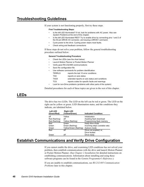
The drive has two LEDs. The LED on the left can be red or green. The LED on the<br />
right can be yellow or green. LED illumination states, and the conditions they<br />
indicate, are tabulated below.<br />
Left LED Right LED<br />
(Green/Red) (Yellow/Green) Indicated Condition:<br />
off Yellow Initialization<br />
Red (flashing) off Awaiting flash download<br />
Red (flashing) Yellow (flashing) Programming flash memory<br />
Red Green Keep Alive mode<br />
Green Green (flashing) Incoming steps (variable rate)<br />
Green Yellow/Green (flashing) Autorun mode<br />
Red off Drive not enabled; or,<br />
Drive faulted<br />
Green off Drive ready<br />
Establish Communications and Verify Drive Configuration<br />
If you cannot enable the drive, and examining LED conditions has not solved your<br />
problem, then establish communications with the drive and launch Motion Planner<br />
or Pocket Motion Planner. (See Chapter 2 Installation for detailed instructions on<br />
establishing communications. Information about installing and using these<br />
software programs can be found in the Gemini Programmer's Reference.)<br />
If you are unable to establish communications, see RS-232/485 Communication<br />
Problems later in this chapter.<br />
48 Gemini GV6 Hardware Installation Guide


