powercoil.com.au wire thread insert system
powercoil.com.au wire thread insert system
powercoil.com.au wire thread insert system

Create successful ePaper yourself
Turn your PDF publications into a flip-book with our unique Google optimized e-Paper software.
®<br />
®<br />
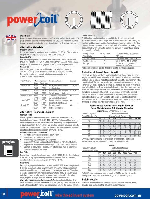
Materials<br />
PowerCoil standard <strong>insert</strong>s are manufactured from fully certified, aircraft quality, 304<br />
(18/8) <strong>au</strong>stenitic stainless steel in accordance with DTD 734A. Alternative materials<br />
include 316 stainless steel and a variety of application specific surface coatings.<br />
Alternative Materials<br />
Phosphor Bronze<br />
Non ferrous copper/tin alloy in accordance with BS2783 PB 102 EH – is suitable<br />
for operation in temperatures ranging from -200ºC to +300ºC.<br />
Inconel X-750<br />
Heat resisting precipitation hardenable nickel base alloy (equivalent specifications<br />
SAE AS 7246, DIN/NF 3018, W.NR 2.4669, UNS N07750). Inconel X-750 is suitable<br />
for operation in temperatures ranging from -200ºC to +550º degrees celsius.<br />
Nimonic 90<br />
Heat resisting precipitation hardenable nickel base alloy in accordance<br />
with BS2 HR 501 (equivalent specifications W.NR 2.4632, UNS N07090).<br />
Nimonic 90 is suitable for operation in temperatures ranging from<br />
-100ºC to +650º degrees celsius.<br />
Insert Material Max. Temperature Typical Applications Coatings<br />
Peak Continuous<br />
Stainless 304 425ºC 315ºC Most general applications FL, AG, CD<br />
800ºF 600ºF in all materials<br />
Stainless 316 425ºC 315ºC Increased corrosion resistance FL, AG, CD<br />
800ºF 600ºF for salt water applications<br />
Phosphor Bronze 300ºC 235ºC Copper parts, non-magnetic, AG, CD<br />
572ºF 455ºF low permeability applications<br />
Iconel X-750 650ºC 550ºC Aerospace, turbines, corrosive AG<br />
1200ºF 1020ºF environments, high temp. use<br />
Nimonic 90 650ºC 550ºC Aerospace and AG<br />
1200ºF 1020ºF turbine applications<br />
Alternative Finishes & Coatings<br />
Cadmium Plate<br />
Electro-deposited Cadmium in accordance with DTD 904/Def Stan 03-19<br />
(equivalent specifications FED. QQ-P-416, LN 9368). Cadmium plating provides<br />
an excellent barrier between dissimilar metals dramatically reducing the effects<br />
of galvanic corrosion, its high lubricity and excellent corrosion resistance prevents<br />
seizure and galling between <strong>thread</strong>ed <strong>com</strong>ponents. Cadmium plate is suitable for<br />
operation in temperatures ranging from -200ºC to +235ºC.<br />
Cadmium plated parts must not be<br />
• sujected to temperatures exceeding 235ºC (455ºF)<br />
• <strong>com</strong>e into contact with fuel or hot oil<br />
• <strong>com</strong>e into contact with food or drinking water<br />
• be used with titanium <strong>com</strong>ponents (either directly or indirectly).At elevated<br />
temperatures embrittlement and subsequent <strong>com</strong>ponent failure may occur.<br />
• Cadmium is highly toxic – consequently extreme care must be taken when<br />
shipping, handling and installing.<br />
Zinc Plate<br />
Electrolytically deposited zinc in accordance with BS 3382. Electro-deposited zinc<br />
is the most widely applied electroplated finish in industry. Zinc is suitable for<br />
operation in temperatures ranging from -200ºC to +250ºC.<br />
Silver Plate<br />
Electrolytically deposited silver in accordance with DTD 939. Silver plating is used<br />
to prevent seizure and galling between <strong>thread</strong> <strong>com</strong>ponents in high temperature<br />
applications and is most <strong>com</strong>monly applied to aero-engine fasteners. Silver plate<br />
is suitable for operation in temperatures ranging from -200ºC to +650ºC. Silver<br />
plated <strong>wire</strong> <strong>insert</strong>s may be installed in various materials including aluminium<br />
alloys, magnesium alloys, corrosion and heat resistant materials etc.<br />
Silver plated <strong>insert</strong>s are not re<strong>com</strong>mended for installation in titanium alloy<br />
which may exceed a service temperature of 300ºC ( 570ºF). Stress corrosion as a<br />
result of the <strong>com</strong>bination of silver and titanium may occur in the housing material.<br />
Dry Film Lubricant<br />
Solid film heat cured molybdenum disulphide dry film lubricant coating in<br />
accordance with MIL-L-0046010 provides a low frictional coefficient coating with<br />
excellent load bearing capabilities. Dry film lubricant prevents seizing and galling<br />
between <strong>thread</strong>ed <strong>com</strong>ponents and is particularly effective in screw locking <strong>insert</strong><br />
applications. Dry film lubricant is suitable for operation in temperatures ranging<br />
from -100ºC to +250ºC.<br />
Plating / Finish Part No. Suffix Applicable Process Specification<br />
Silver Plating AG DTD 939<br />
Cadmium Plating CD QQP-416 or DEF STD 03-19<br />
Dry Film Lubricant FL MIL-L-8937 or MIL-L-46010<br />
Red Dye – Applied to locking <strong>insert</strong>s for<br />
identification purposes*<br />
* other color dyes may also be utilised for specific identification purposes<br />
Selection of Correct Insert Length<br />
PowerCoil <strong>wire</strong> <strong>thread</strong> <strong>insert</strong>s are available in all popular <strong>thread</strong> types. Five <strong>insert</strong><br />
lengths are available for each <strong>thread</strong> size. It is important to select the correct <strong>insert</strong><br />
length in order to balance the bolt tensile strength against the shear strength of the<br />
parent material. The five <strong>insert</strong> lengths (re<strong>com</strong>mended <strong>thread</strong> engagement of the<br />
PowerCoil <strong>wire</strong> <strong>thread</strong> <strong>insert</strong>), 1D, 1.5D, 2D, 2.5D and 3D are shown in the shaded<br />
area of the table below. These are calculated numbers since the <strong>insert</strong>s cannot be<br />
measured in the free (un-installed) state. The numbers are multiples of the nominal<br />
<strong>thread</strong> size, or diameter, of the <strong>insert</strong>. The actual <strong>insert</strong> lengths in the installed<br />
position are listed in the <strong>insert</strong> selection tables. There they represent the actual<br />
installed length plus 1/2 pitch. Using the table below, an <strong>insert</strong> length can be<br />
selected which will produce a <strong>thread</strong> <strong>system</strong> strong enough to fracture a bolt before<br />
it will strip or damage either the parent material or the <strong>insert</strong>.<br />
Re<strong>com</strong>mended Nominal Insert lengths Based on<br />
Parent Material Versus Bolt Material Strengths<br />
UNIFIED (source BS7752 Part 1:1994)<br />
Shear Strength of<br />
Bolt Material Minimum<br />
Parent Material (KSI)<br />
Ultimate Tensile Strength (KSI)<br />
54 75 96 108 125 132 160 180 220<br />
10 2.0 2.5 3.0 3.0 – – – – –<br />
15 1.5 1.5 2.0 2.5 2.5 3.0 – – –<br />
20 1.0 1.5 1.5 2.0 2.0 2.0 2.5 3.0 3.0<br />
25 1.0 1.0 1.5 1.5 1.5 2.0 2.0 2.5 2.5<br />
30 1.0 1.0 1.0 1.5 1.5 1.5 2.0 2.0 2.5<br />
40 1.0 1.0 1.0 1.0 1.0 1.5 1.5 1.5 2.0<br />
50 1.0 1.0 1.0 1.0 1.0 1.0 1.0 1.5 1.5<br />
EXAMPLE: If parent material shear strength is 10KSI and the bolt tensile<br />
strength is 54 KSI, the correct <strong>insert</strong> length is 2.0 diameters (2D).<br />
METRIC<br />
Shear Strength of<br />
Bolt Material Minimum<br />
Parent Material (MPa)<br />
Ultimate Tensile Strength (MPa)<br />
300 400 500 600 800 1000 1200 1400<br />
70 1.5 2.0 2.5 2.5 – – – –<br />
100 1.0 1.5 1.5 2.0 2.5 3.0 – –<br />
150 1.0 1.0 1.5 1.5 2.0 2.0 2.5 3.0<br />
200 1.0 1.0 1.0 1.0 1.5 1.5 2.0 2.5<br />
250 1.0 1.0 1.0 1.0 1.0 1.5 1.5 2.0<br />
300 1.0 1.0 1.0 1.0 1.0 1.5 1.5 1.5<br />
350 1.0 1.0 1.0 1.0 1.0 1.0 1.5 1.5<br />
EXAMPLE: If parent material shear strength is 150Mpa and the bolt tensile<br />
strength is 600Mpa, the correct <strong>insert</strong> length is 1.5 diameters (1.5D).<br />
Bolt Projection<br />
PowerCoil <strong>wire</strong> <strong>thread</strong> <strong>insert</strong>s are designed to be used with standard, readily<br />
available bolts and screws that require no special hardware.<br />
®<br />
68<br />
<strong>wire</strong> <strong>thread</strong> <strong>insert</strong> <strong>system</strong><br />
<strong>powercoil</strong>.<strong>com</strong>.<strong>au</strong>