SunTouch® - Pentair
SunTouch® - Pentair
SunTouch® - Pentair

Create successful ePaper yourself
Turn your PDF publications into a flip-book with our unique Google optimized e-Paper software.
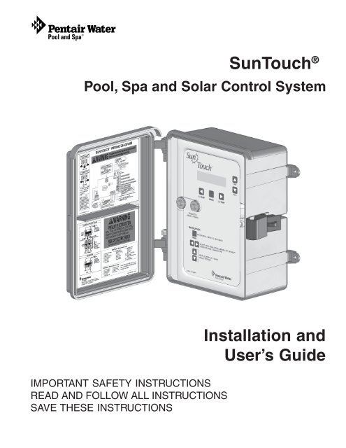
SunTouch ®<br />
Pool, Spa and Solar Control System<br />
IMPORTANT SAFETY INSTRUCTIONS<br />
READ AND FOLLOW ALL INSTRUCTIONS<br />
SAVE THESE INSTRUCTIONS<br />
Installation and<br />
User’s Guide
© 2011 <strong>Pentair</strong> Water Pool and Spa, Inc. All rights reserved<br />
1620 Hawkins Ave., Sanford, NC 27330 • (919) 566-8000<br />
10951 West Los Angeles Ave., Moorpark, CA 93021 • (805) 553-5000<br />
SunTouch ® , IntelliChlor ® , IntelliFlo ® , IntelliChem, QuickTouch® , Sta-Rite®, MiniMax®, MasterTemp® and <strong>Pentair</strong><br />
Water Pool and Spa® are trademarks and/or registered trademarks of <strong>Pentair</strong> Water Pool and Spa, Inc. and/or its<br />
affiliated companies in the United States and/or other countries. Intermatic® is a registered trademark of Intermatic<br />
Inc. RayPak® is a registered trademark of Rheam Company. Hatward® is a registered trademark of Hayward<br />
Industries Inc. Jandy® is a registered trademark of Jandy Pool Products Inc. Unless noted, names and brands of<br />
others that may be used in this document are not used to indicate an affiliation or endorsement between the<br />
proprietors of these names and brands and <strong>Pentair</strong> Water Pool and Spa, Inc. Those names and brands may be the<br />
trademarks or registered trademarks of those parties or others.<br />
P/N 520785 - Rev C 02/08/11
i<br />
Contents<br />
IMPORTANT WARNING AND SAFETY INSTRUCTIONS ................................................................ iii<br />
Technical Support ............................................................................................................................ vi<br />
Section 1: SunTouch Pool and Spa Control System Overview.................................................... 1<br />
SunTouch Control System Overview ................................................................................................. 1<br />
SunTouch Solar Mode .................................................................................................................. 1<br />
SunTouch Pool/Spa Mode ............................................................................................................ 1<br />
SunTouch Control Panel ................................................................................................................... 2<br />
SunTouch Control Buttons............................................................................................................ 2<br />
SunTouch Main Status Screen (Solar Only mode) ............................................................................ 4<br />
SunTouch Solar Only System .......................................................................................................... 4<br />
Operating SunTouch in Solar Only Mode .......................................................................................... 5<br />
Setting up SunTouch for Solar Only mode from Pool/Spa mode.................................................... 5<br />
Adjusting the water temperature setting (Solar Only mode) .......................................................... 6<br />
Solar Only Menus ........................................................................................................................ 6<br />
Set Temperature ...................................................................................................................... 6<br />
System Control ........................................................................................................................ 7<br />
System Mode .......................................................................................................................... 7<br />
Time Set .................................................................................................................................. 7<br />
Start and Stop Temp Differentials ............................................................................................. 8<br />
Solar Freeze protection............................................................................................................ 8<br />
Cleaner Freeze protection ........................................................................................................ 8<br />
Air sensor ................................................................................................................................ 8<br />
Freeze Protection in Solar Only mode .......................................................................................... 9<br />
Operating SunTouch in Pool/Spa mode (Shared Equipment) ............................................................. 9<br />
Setting up SunTouch to Operate in Pool/Spa mode ...................................................................... 9<br />
Adjusting the water temperature setting in Pool/Spa mode ........................................................... 9<br />
Selecting the heat source ............................................................................................................ 10<br />
SunTouch Main Status Screen (Pool/Spa mode - Shared Equipment) .......................................... 11<br />
Pool/Spa Mode Menus (Shared Equipment) ................................................................................. 12<br />
Pool/Spa Mode Menus .................................................................................................................. 13<br />
Circuit On/Off Menu (1/14)............................................................................................................ 13<br />
Heat Menu (2/14) ......................................................................................................................... 14<br />
Pool Temperature and Heat Source settings ............................................................................ 14<br />
Spa Temperature and Heat Source ........................................................................................... 15<br />
HI-TEMP /LO-TEMP (Pool or Spa) Control Button .................................................................... 15<br />
Manual Heat (Off/On) ............................................................................................................... 15<br />
Delay Cancel Menu (3/14) ............................................................................................................ 16<br />
Schedules Menu (4/14) ................................................................................................................ 17<br />
Schedule your Spa or Pool ...................................................................................................... 18<br />
Edit an existing program .......................................................................................................... 18<br />
Delete a program ..................................................................................................................... 18<br />
Clock Menu (5/14) ........................................................................................................................ 19<br />
Solar Menu (6/14) ........................................................................................................................ 19<br />
Valves Menu (7/14)....................................................................................................................... 21<br />
Advanced Menu (8/14): Heater and Valve Delays .......................................................................... 22<br />
Advanced Menu (8/14): Temp Units - F° / C° (Fahrenheit/Celsius) ................................................ 22<br />
Advanced Menu (8/14): Calibrate water, air and solar sensors ...................................................... 23<br />
Advanced Menu (8/14): Air Sensor Enable/Disable ....................................................................... 24<br />
Advanced Menu (8/14): System Mode .......................................................................................... 24<br />
SunTouch Solar, Pool and Spa Control System Installation and User’s Guide
ii<br />
Contents<br />
Advanced Menu (8/14): System Type ........................................................................................... 24<br />
Advanced Menu (8/14): Circuit Time Out ...................................................................................... 24<br />
Advanced Menu (8/14): Reset Factory.......................................................................................... 25<br />
Diagnostics Menu (9/14): Firmware Rev ....................................................................................... 25<br />
Diagnostics Menu: Solar Temp ................................................................................................ 25<br />
Diagnostics Menu: Self Test .................................................................................................... 25<br />
Diagnostics Menu: IntelliChem................................................................................................. 25<br />
Circuit Functions Menu (10/14) .................................................................................................... 26<br />
Assigning Circuit Functions .......................................................................................................... 26<br />
Freeze Protection .................................................................................................................... 26<br />
Circuit Functions ..................................................................................................................... 26<br />
Preset Circuit Functions .......................................................................................................... 27<br />
Settings Menu (11/14): QuickTouch (QT4) Wireless Remote ........................................................ 28<br />
Assign QT4 buttons ................................................................................................................. 28<br />
Pump Menu (12/14) ..................................................................................................................... 28<br />
Single speed filter pump .......................................................................................................... 28<br />
Two-speed filter pump .............................................................................................................. 29<br />
IntelliFlo VS pump .................................................................................................................. 30<br />
Freeze Protection ............................................................................................................. 30<br />
IntelliFlo VF pump................................................................................................................... 32<br />
IntelliFlo VSF+SVRS pump .................................................................................................... 35<br />
IntelliChlor Menu (13/14) ................................................................................................................... 36<br />
IntelliChlor Menu (13/14): Status and Error Messages ............................................................. 36<br />
Service Menu (14/14): Service, Timeout, Auto ................................................................................... 38<br />
SunTouch Main Status Screen (Pool/Spa Mode - Single Body System)............................................ 39<br />
High/Low Temperature Circuit Control (Single Body System) ............................................................ 40<br />
HI-TEMP / LO-TEMP Circuit Controls ........................................................................................... 40<br />
Setting up SunTouch to operate as a Single Body system ........................................................... 40<br />
Pool/Spa Mode (Single Body of Water) Menus ............................................................................. 41<br />
Section 2: Installation and Setup .................................................................................................. 42<br />
SunTouch System Installation Steps Summary ................................................................................ 42<br />
Required Tools ............................................................................................................................. 42<br />
SunTouch Solar Package Contents .................................................................................................. 43<br />
SunTouch Control System Contents ................................................................................................. 43<br />
Replacement Parts ...................................................................................................................... 43<br />
Optional Equipment ..................................................................................................................... 43<br />
SunTouch System Overview ......................................................................................................... 44<br />
Plumbing Requirements ................................................................................................................... 46<br />
Equipment Location ..................................................................................................................... 47<br />
Solar Hydraulics System ............................................................................................................. 48<br />
SunTouch Power Center High Voltage Connections .......................................................................... 49<br />
SunTouch Power Center Location ..................................................................................................... 49<br />
Grounding and Bonding to the SunTouch Power Center ................................................................ 50<br />
Preparing the SunTouch Power Center ......................................................................................... 51<br />
Opening the front panel ................................................................................................................ 51<br />
Mounting the SunTouch Power Center .............................................................................................. 52<br />
Removing Electrical Conduit Knockouts ....................................................................................... 53<br />
Installing Conduit and Wire to the SunTouch Power Center .......................................................... 54<br />
Transformer Connections .................................................................................................................. 55<br />
High Voltage Wiring ..................................................................................................................... 55<br />
SunTouch Motherboard Connections ................................................................................................ 56<br />
Equipment Power ......................................................................................................................... 56<br />
Accessing the SunTouch Motherboard............................................................................................. 57<br />
Installing Auxiliary Relays ................................................................................................................. 58<br />
Relay locations ............................................................................................................................ 58<br />
Installing relays ............................................................................................................................ 58<br />
SunTouch Solar, Pool and Spa Control System Installation and User’s Guide
iii<br />
Contents<br />
Installing Valve Actuators................................................................................................................ 60<br />
Adjusting the valve position .......................................................................................................... 60<br />
Installing and Connecting Temperature Sensors ............................................................................... 61<br />
Water Temperature Sensor .......................................................................................................... 61<br />
Ambient Air Temperature Sensor (for freeze protection) ................................................................ 61<br />
Solar Temperature Sensor ............................................................................................................ 61<br />
Connecting SunTouch to a Gas Heater ............................................................................................. 62<br />
Connecting to a standard heater .................................................................................................. 62<br />
Connecting to a MiniMax®, MasterTemp® Gas Heater ................................................................ 62<br />
Connecting to a Sta-Rite® Gas Heater ......................................................................................... 63<br />
Connecting a Standard Heat Pump or Electric Heater .................................................................. 63<br />
SunTouch Solar System Installation ................................................................................................. 64<br />
SunTouch Solar System Start-Up ................................................................................................. 64<br />
Pool Cleaner Protection ............................................................................................................... 64<br />
SunTouch Pool/Spa Controller System Start-Up ........................................................................... 65<br />
Check Electronics ........................................................................................................................ 65<br />
SunTouch System Test ................................................................................................................ 65<br />
Testing the auxiliary relays .......................................................................................................... 65<br />
Setting up the SunTouch system for the first time (after equipment Installation) ................................ 66<br />
Section 3: Troubleshooting ............................................................................................................ 68<br />
Frequently Asked Questions (FAQ) .................................................................................................. 68<br />
How do I setup a two-speed pump? .............................................................................................. 68<br />
Can I switch the heater on and change the temperature from the spa? ......................................... 68<br />
How do I switch on solar heating? ................................................................................................ 68<br />
SunTouch Error Messages ............................................................................................................... 69<br />
Error Messages ........................................................................................................................... 69<br />
Self Test Error Codes ................................................................................................................... 69<br />
Error Code Table .......................................................................................................................... 69<br />
Resetting the System Fuses ............................................................................................................ 69<br />
Problem Solving a Solar System ...................................................................................................... 70<br />
SunTouch solar is not operating ................................................................................................... 70<br />
Water flow to panels switch does not operate the valve actuator .................................................. 70<br />
Checking The Temperature Sensors ............................................................................................. 70<br />
Testing the Solar System ................................................................................................................. 70<br />
Air Sensor Error ........................................................................................................................... 70<br />
Temperature vs. Resistance Data ..................................................................................................... 71<br />
IntelliChlor Error Messages .............................................................................................................. 72<br />
System Problem Diagnosis .......................................................................................................... 72<br />
Problem: The Quick Touch remote will not work, or will not work dependably. ............................. 73<br />
IntelliFlo Warning and Alarm Conditions ........................................................................................... 74<br />
Alarm and warning LED sequence ................................................................................................ 74<br />
SunTouch Specifications................................................................................................................... 74<br />
Wiring SunTouch to the IntelliChlor Salt Chlorine Generator .............................................................. 75<br />
Wiring Description (SunTouch ® to IntelliChlor ® , Hayward ® , Jandy ® ) ............................................... 75<br />
Wiring IntellilChlor (SCG) and Standard Pump to SunTouch ......................................................... 76<br />
Wiring IntellilChlor (SCG) and IntelliFlo ® Pump to SunTouch ......................................................... 77<br />
Appendix ........................................................................................................................................ 78<br />
Emergency Shut-Off switch (ESO3) ................................................................................................. 78<br />
Location ....................................................................................................................................... 78<br />
Installing the (ESO3) Circuit Board ............................................................................................... 79<br />
Commercial Application using ESO3 and SunTouch (Single Body System) .................................. 81<br />
Glossary .......................................................................................................................................... 82<br />
SunTouch Solar, Pool and Spa Control System Installation and User’s Guide
iv<br />
IMPORTANT WARNING AND SAFETY INSTRUCTIONS<br />
Important Notice:<br />
Attention Installer: This manual contains important information about the installation, operation and safe use of<br />
this product. This information should be given to the owner and/or operator of this equipment. When installing<br />
and using this electrical equipment, basic safety precautions should always be followed, including the following:<br />
WARNING:<br />
IMPORTANT SAFETY INSTRUCTIONS PERTAINING TO A RISK OF FIRE, ELECTRIC<br />
SHOCK, OR INJURY TO PERSONS. READ AND FOLLOW ALL INSTRUCTIONS.<br />
• DANGER! RISK OF ELECTRIC SHOCK, WHICH CAN RESULT IN SERIOUS INJURY OR DEATH.<br />
Before attempting installation or service, ensure that all power to the circuit supplying power to the<br />
system is disconnected/turned off at the circuit breaker.<br />
• Grounding (earth bonding) is required. The SunTouch Power Center should be installed by a qualified<br />
professional and grounded.<br />
• Read Safety Precautions and Important Instructions. Before attempting any electrical wiring, be<br />
sure to read and follow Safety Instructions. Wiring should only be performed by a qualified<br />
professional.<br />
WARNING - Before installing this product, read and follow all warning notices and instructions which are<br />
included. Failure to follow safety warnings and instructions can result in severe injury, death, or property<br />
damage. Call (800) 831-7133 for additional free copies of these instructions.<br />
WARNING - Water temperature in excess of 100 degrees Fahrenheit may be hazardous to your health.<br />
Prolonged immersion in hot water may induce hyperthermia. Hyperthermia occurs when the internal temperature<br />
of the body reaches a level several degrees above normal body temperature of 98.6° F (37° C). The symptoms<br />
of hyperthermia include drowsiness, lethargy, dizziness, fainting, and an increase in the internal temperature of<br />
the body.<br />
The effects of hyperthermia include: 1) Unawareness of impending danger. 2) Failure to perceive heat. 3) Failure<br />
to recognize the need to leave the spa. 4) Physical inability to exit the spa. 5) Fetal damage in pregnant women.<br />
6) Unconsciousness resulting in danger of drowning.<br />
WARNING - To reduce the risk of injury, do not permit children to use this product unless they are closely<br />
supervised at all times.<br />
WARNING - The use of alcohol, drugs, or medication can greatly increase the risk of fatal<br />
hyperthermia in hot tubs and spas.<br />
WARNING - Control System is intended to control heaters with built-in high limit circuits ONLY. Failure to do<br />
so may cause property damage or personal injury. All water will be routed through the heater assembly.<br />
WARNING - Do not use this product to control an automatic pool cover. Swimmers may become entrapped<br />
underneath the cover.<br />
SunTouch Solar, Pool and Spa Control System Installation and User’s Guide
v<br />
IMPORTANT WARNING AND SAFETY INSTRUCTIONS<br />
General Installation Information<br />
1. All work must be performed by a licensed electrician, and must conform to all national, state, and local<br />
codes.<br />
2. Install to provide drainage of compartment for electrical components.<br />
3. If this system is used to control underwater lighting fixtures, a ground-fault circuit interrupter (GFCI)<br />
must be provided for these fixtures. Conductors on the load side of the ground-fault circuit-interrupter<br />
shall not occupy conduit, junction boxes or enclosures containing other conductors unless such<br />
conductors are also protected by a ground-fault circuit-interrupter. Refer to local codes for details.<br />
4. A terminal grounding bar stamped is located inside the SunTouch Power Center. To reduce the<br />
risk of electric shock, this terminal must be connected to the grounding means provided in the electric<br />
supply service panel with a continuous copper wire equivalent in size to the circuit conductors<br />
supplying this equipment (no smaller than 12 AWG or 3.3 mm). The bonding lug(s) provided on this unit<br />
are intended to connect a minimum of one No. 8 AWG for US installation and two No. 6 AWG for<br />
Canadian installations solid copper conductor between this unit and any metal equipment, metal<br />
enclosures or electrical equipment, metal water pipe, or conduit within 5 feet (1.5 m) of the unit.<br />
5. The electrical supply for this product must include a suitably rated switch or circuit breaker to open all<br />
ungrounded supply conductors to comply with National Electrical Code (NEC), NFPA 70 or the<br />
Canadian Electrical Code (CEC), CSA C22.1. The disconnecting means must be readily accessible to<br />
the tub occupant but installed at least 10 ft. (3.05 m) from the inside wall of the pool.<br />
6. Supply conductor must be sized to support all loads.<br />
Safety Notice<br />
Important Safety Instructions<br />
When installing and using this electrical equipment, basic safety precautions should always be<br />
followed, including the following:<br />
READ AND FOLLOW ALL INSTRUCTIONS:<br />
WARNING - To reduce the risk of injury, do not permit children to use this product unless they<br />
are closely supervised at all times.<br />
WARNING - Water in excess of 100 degrees Fahrenheit may be hazardous to your health.<br />
WARNING - For units intended for use in other than single-family dwellings, a clearly labeled<br />
emergency switch shall be provided as part of the installation. The switch shall be readily<br />
accessible to the occupants and shall be installed at least 10 feet (3.05 m) away, adjacent to, and<br />
within sight of, the unit.<br />
Two Speed Pump Controls Notice (Title 20 Compliance)<br />
Please read the following important Safety Instructions (See page 28 for pump speed setup)<br />
When using two-speed pumps manufactured on or after January 1, 2008, the pump’s default<br />
circulation speed MUST be set to the LOWEST SPEED, with a high speed override capability being<br />
for a temporary period not to exceed one normal cycle, or two hours, whichever is less.<br />
SunTouch Solar, Pool and Spa Control System Installation and User’s Guide
vi<br />
Technical Support<br />
Sanford, North Carolina (8 A.M. to 5 P.M. ET)<br />
Moorpark, California (8 A.M. to 5 P.M. PT)<br />
Phone: (800) 831-7133<br />
Fax: (800) 284-4151<br />
Web sites<br />
visit www.pentairpool.com and staritepool.com<br />
SunTouch Solar, Pool and Spa Control System Installation and User’s Guide
1<br />
SunTouch ® Control System Overview<br />
Section 1<br />
Overview<br />
Congratulations! On your purchase of the <strong>Pentair</strong> Water Pool and Spa ® “<strong>Pentair</strong>,” SunTouch ® pool and spa<br />
control system - The next generation in intelligent control systems. The SunTouch quick-access menus helps<br />
you to setup control of your pool and spa daily operations. Your system can be easily configured to operate in<br />
“Solar Only” mode for solar systems, “Pool/Spa” mode for shared equipment systems or “Single Body of<br />
Water” mode for single equipment systems.<br />
The SunTouch system supports the <strong>Pentair</strong> IntelliChem, water chemistry controller, IntelliChlor ® salt<br />
chlorine generator, for pool water sanitizing and IntelliFlo ® VS and IntelliFlo ® VF pumps to meet all your pool<br />
and spa needs. For a complete list of SunTouch systems and optional equipment see to page 43.<br />
SunTouch Solar Mode<br />
The SunTouch Solar system provides automatic solar heating control using a differential temperature control<br />
designed especially for solar-heated swimming pool, spas, and hot tubs. Also included is solar nocturnal cooling<br />
control for optimizing heat control at night. Whenever solar energy is available, SunTouch will automatically<br />
activate a motorized three-port solar valve and/or the optional solar booster pump which controls the water<br />
flow direction, and pump pool water through the solar collectors. The filter pump timer can be set so the filter<br />
pump is operating during that time of the day when solar energy is available.<br />
If you are using a pool cleaner booster pump for your pool, SunTouch will disable the pump for five minutes<br />
whenever the solar system turns on. This protects the pump from possible damage caused by residual air<br />
within the solar panels.<br />
Note: For information about setting up and operating SunTouch as a solar only system, see page 5.<br />
SunTouch Pool/Spa Mode<br />
SunTouch “Pool/Spa” mode provides automation controls for pool and spa shared equipment systems or for<br />
pool only or spa only “Single Body” systems. With the addition of two valve actuators, SunTouch can be<br />
configured to control your pool and spa heating and filtration schedules and additional features such as pool<br />
lights, automatic cleaners, or waterfalls.<br />
Using the optional QuickTouch ® (QT4) wireless remote controller you can control up to four circuits to<br />
activate the spa circulation, and for operating three auxiliary pieces of equipment (such as lights, jet pump, air<br />
blower, waterfall, etc.). For more information, see “Main Menu: QuickTouch (QT4) Wireless Remote,” on<br />
page 28.<br />
Note: For information about setting up and operating SunTouch as a standard pool and spa controller<br />
in “Pool/Spa” mode, see page 9.<br />
SunTouch Power Center<br />
SunTouch Solar, Pool and Spa Control System Installation and User’s Guide
2<br />
SunTouch Control Panel<br />
Use the SunTouch control panel buttons to program and control pool and spa operations. You can schedule<br />
daily operations to run automatically using the SunTouch menu features, and manually adjust temperature<br />
settings, switch lights on and off, and setup pool/spa equipment. The SunTouch LCD displays the current<br />
temperature settings, current time and equipment status information.<br />
Actual temperature<br />
Set temperature<br />
➄<br />
®<br />
➀<br />
SPA 71°F / 91°F<br />
11:51AM HEATER<br />
➃<br />
SunTouch Control Buttons<br />
➀<br />
➁<br />
Liquid Crystal Display (LCD): The main system display consists of a 16 x 2 alphanumeric character<br />
LCD with backlighting for easy viewing.<br />
Pool and Spa status display: While SunTouch is in normal day-to-day operations, the main status<br />
screen will toggle between the pool (or spa) set (and actual) temperature, and the current air<br />
temperature (if an air sensor is installed, see page 24 for details). The current system time is displayed<br />
on the lower left side of the screen. The heating source (if enabled) is displayed on the lower right side<br />
of the screen. To switch the pool circuit on and display the pool temperature, the pool circuit must be set<br />
to “On” (see Circuit On/Off Menu (1/14) on page 13 for details). To activate the Spa, press the Up<br />
arrow button to view the current Spa temperature. For more information about the spa Up arrow button,<br />
see page 3.<br />
MENU<br />
Main Menu 1/14<br />
Circuit On/Off<br />
➂<br />
➁<br />
➂<br />
SunTouch Control Panel<br />
(Pool/Spa mode - Shared Equipment System)<br />
MENU button: Use the MENU button to access the Main Menu items. There are 14<br />
menu items to select from. Press the MENU button to view each of the 14 menu<br />
items. The Main Menu items are displayed along with its menu number (1/14). Use<br />
the Menu button to scroll through the 14 menu items. To exit a menu item at any point,<br />
press the Left button to return to the main status screen. If no menu activity is<br />
detected after five minutes, the main screen is displayed. All menu settings are<br />
permanently saved and retained in the SunTouch control panel even after power is<br />
removed from the control panel. For descriptions of the Main Menu items using<br />
“Pool/Spa” mode see page 13.<br />
➅<br />
SunTouch Solar, Pool and Spa Control System Installation and User’s Guide
3<br />
Control Buttons (Continued)<br />
➂<br />
➃<br />
➄<br />
(-) TEMP<br />
(+) TEMP<br />
Set temperature<br />
Actual temperature<br />
POOL 71°F / 91°F<br />
11: 51AM HEATER<br />
SPA 71°F / 91°F<br />
11: 51AM HEATER<br />
SPA<br />
SPA 71°F / 91°F<br />
11: 51AM HEATER<br />
Left button: While in the Main menu, use the Left arrow button to exit the main menu<br />
and return to the Main status screen.<br />
Right button: While in the Main menu, use the Right arrow button to select a setting<br />
or parameter, or scroll through the available selected menu items. To exit the Main<br />
menu, press the Left arrow button.<br />
(-) TEMP) and (+)TEMP button temperature controls: When in Pool or Spa mode,<br />
press the (-) TEMP button to lower set temperature or the (+) TEMP button to raise<br />
the set temperature for the pool or spa water. Note: The pool filter pump circuit<br />
must be switched on to display the current pool temperature settings. “HEATER”<br />
is displayed on the lower line of the main screen indicating the current heat<br />
source is switched on (enabled). For more information about selecting a heat<br />
source, see the “Selecting a Heat Source” on page 10. For information about<br />
switching on the filter pump circuit, see “Main Menu: Circuit On/Off (1/14)” on page<br />
13. These buttons are only used in Pool/Spa mode. For information about Pool/Spa<br />
mode, see page 9.<br />
Up and Down arrow button: While in the Main Menu, use the Up and Down arrow<br />
buttons to adjust or change a menu item parameter or setting. The Up button<br />
increases a value, or toggles a setting. The Down arrow button decreases a value, or<br />
toggles a setting. After changing a menu item setting or value, it is automatically<br />
saved.<br />
SPA (Up arrow button): Use this button to switch the spa on and off. When the spa is<br />
activated, the main screen will display the actual and set point temperature setting.<br />
Press this button to activate the filter pump and rotate the valves and circulate pool<br />
water to the spa. To enable heat for the spa when this circuit is switched on, either<br />
switch on the heat source or switch on Manual Heat from the Heat menu. HEATER<br />
(or SOLAR) is displayed when the heat source is enabled. If the Spa button is<br />
pressed, while the filter pump is active (see page 13 to enable the pool filter pump),<br />
the spa valves will rotate to circulate water to the spa. When the Spa (Up arrow)<br />
button is pressed to switch the spa off, the filter pump will rotate the valves to<br />
circulate water to pool and continue to operate in pool mode. The Spa button function<br />
is only used in Pool/Spa mode. For information about Pool/Spa mode, see page 9.<br />
Note: For Single Body systems, the UP arrow button is used for the HI-TEMP/<br />
LO-TEMP temperature control. For more information about the HI-TEMP/LO<br />
TEMP button temperature control, see page 40.<br />
➅<br />
AUX 1<br />
AIR 71°F<br />
11: 51AM AUX 123<br />
AIR 71°F<br />
11: 51AM AUX D23<br />
AUX 1 (Down arrow On/Off button): Use the AUX 1 (Down arrow) button to<br />
manually switch the AUX 1 relay output on and off. You can also switch AUX 2, and<br />
AUX 3 on and off from the “Circuit On/Off menu. The number 1, 2, and 3 will be<br />
displayed on the main screen when the auxiliary circuits are switched on. The AUX 1,<br />
AUX 2 and AUX 3 functions are only used in “Pool/Spa” mode. For information<br />
about “Pool/Spa” mode, see page 9.<br />
Note: In the example shown (left), AUX D is displayed, indicating that AUX 1 is<br />
currently in “delay” mode and is not yet active. The same applies when AUX 2<br />
or AUX 3 are in “Delay” mode. See “Assigning Circuit Functions” on page 26<br />
for more information.<br />
SunTouch Solar, Pool and Spa Control System Installation and User’s Guide
4<br />
SunTouch Main Status Screen (Solar Only)<br />
The SunTouch “Solar Only” main status screen display description is given below.<br />
®<br />
11:51 AM<br />
AIR 85°F<br />
Use Up/Down<br />
buttons for menu<br />
navigation only<br />
(see “Up and down<br />
arrow button”<br />
on page 3).<br />
Lower current set point Raise current set point<br />
temperature setting temperature setting<br />
Actual temperature Set temperature<br />
Water temperature settings: Displays the<br />
actual (77°F) and set point (90°F) water<br />
WATER 77°/ 90°F<br />
temperature. Adjust the water temperature<br />
in “Set Water Temp” menu (page 6).<br />
11:51 AM SOL ON<br />
Main Screen: In “Solar Only” mode the main<br />
screen display toggles between the current<br />
outside air temperature, and the actual and set<br />
water temperature, and current solar status<br />
(SOL ON/OFF). The system time also displays<br />
as set in the “Time Set” menu. In order to<br />
display the air temperature, an optional air<br />
sensor is required. The air sensor is also used<br />
for freeze protection. The filter pump and<br />
optional relay must be connected to an<br />
external time clock for freeze protection to work.<br />
The air sensor can be enabled and disabled<br />
from the “Solar Only” menu.<br />
SunTouch Control Panel (Solar Only mode)<br />
SOL ON: Displays when solar heat is<br />
available and water is circulating through<br />
the collector array. Solar heat is available<br />
when the set point water temp is higher<br />
than the solar temperature and the solar<br />
temperature is higher than the actual<br />
water temperature.<br />
SOL OFF: Displays when solar heat is not<br />
available (i.e. when the set point water<br />
temp is lower than the solar temperature<br />
and the solar temperature is lower than the<br />
actual water temperature.<br />
SunTouch Solar Only System<br />
The SunTouch “Solar Only” system is factory set and ready to operate. From the main menu you can adjust<br />
the water temperature setting, set the start and stop differential temperatures, and set the solar and cleaner<br />
freeze protection feature. If additional features are required, such as a solar booster pump, you can access the<br />
“Pool/Spa” mode (shared equipment) menu features. For more information about these modes, refer to “Solar<br />
Only Menus,” on page 6, and “Pool/Spa Mode Menus (Shared Equipment)” on page 12.<br />
SunTouch Solar, Pool and Spa Control System Installation and User’s Guide
5<br />
Operating SunTouch in Solar Only Mode<br />
SunTouch Solar Only mode<br />
In “Solar only” mode, you can control your SunTouch solar system to heat your pool and spa. From the control<br />
panel you can set the desired temperature setting. After the temperature is reached, the solar system is<br />
automatically switched off.<br />
Solar Only auxiliary outputs (Filter pump, booster pump, cleaner and time clock)<br />
Filter pump: In “Solar Only” mode, the Filter pump is controlled externally by the time clock, which ensures<br />
the Filter pump is running before the Booster pump switches on.<br />
Booster pump: To increase water flow through the collector array, a high voltage booster pump can be used in<br />
addition to the main Filter pump. The Booster pump will switch on at the same time as the Filter pump, assuming<br />
solar heat is available. When using a Booster pump, connect it to the AUX 1 relay in the SunTouch Power<br />
Center. For SunTouch solar booster kit (P/N 520857) information, see page 43.<br />
• Pump output on the SunTouch motherboard is on whenever solar heat is available and off whenever<br />
Solar heat is not available<br />
• AUX 1/Booster pump is on whenever Solar heat is available and off whenever solar heat is not<br />
available<br />
• AUX 2 (Cleaner): The cleaner is off for five minutes when solar heat is detected.<br />
SunTouch Pool/Spa Mode<br />
In Pool/Spa mode you can fully automate your pool and spa, pool only or spa only operations. The additional<br />
SunTouch menu features let you create customized schedules for your pool and spa equipment, heat<br />
temperatures, and chlorination settings to switch on and off at a set day and time. For maintenance and service<br />
purposes, the control panel allows manual control of all pool and spa operations. For information about<br />
Pool/Spa mode, see page 9.<br />
Setting up SunTouch for Solar Only mode from Pool/Spa mode<br />
To change the SunTouch controller to “Solar Only” mode while in Pool/Spa mode:<br />
SunTouch<br />
11: 51 AM<br />
MENU<br />
Press the MENU button to<br />
access the Main Menu items<br />
▼<br />
Main Menu 8/14<br />
Advanced<br />
MENU<br />
Press the MENU button<br />
until “Advanced” displays<br />
▼<br />
System Mode<br />
Solar Only<br />
Press the Left or Right<br />
button to access the<br />
“System Mode” options<br />
Press either<br />
Up or Down<br />
button and select<br />
“Solar Only”<br />
Press the Left or<br />
Right button to<br />
save and exit.<br />
To continue to set the solar heat settings, press the LEFT or RIGHT arrow button to enter the solar water<br />
temperature settings.<br />
Note: If the SunTouch system is configured to operate as a “SOLAR ONLY” controller, all solar features<br />
are provided in the “Solar Only” menu settings (see page 6) with the exception of changing the degree<br />
units from Fahrenheit to Celsius (see page 22), and the Service operating features, which can be<br />
changed in the “Pool/Spa” mode menu (see page 9 for more information).<br />
SunTouch Solar, Pool and Spa Control System Installation and User’s Guide
6<br />
Solar Only Menus<br />
The SunTouch “Solar Only” mode menus are shown below:<br />
Set Water Temp<br />
System Control<br />
System Mode<br />
Time Set<br />
Heat Start Temp Diff<br />
Heat StopTemp Diff<br />
Cooling<br />
Temp: [40˚F - 104˚F or (4˚C - 40˚C)<br />
Auto, Solar OFF, Solar ON<br />
Solar Only [Pool/Spa]<br />
Time Set: Hour/Minutes - AM/PM<br />
Temp Diff: [3˚ - 9˚F]<br />
Temp Diff: [2˚ - 5˚F]<br />
Enabled: No [Yes]<br />
Adjusting the water temperature setting (Solar Only mode)<br />
If you have already set the pool and spa water temperature in the “SET WATER TEMP” menu and you need<br />
to adjust the water set point temperature, use the (-) TEMP or (+) TEMP) buttons to adjust the water<br />
temperature.<br />
• Press the (-) TEMP or (+) TEMP) button to lower or raise the set temperature to the desired level.<br />
The water temperature can be adjusted from 40° F to 104° F (4° C to 40° C). When solar heat is<br />
available SOL ON is displayed on the lower display line. SOL OFF is displayed if solar heat is not<br />
available (OFF). Degree units are displayed in either Fahrenheit or Celsius (see page 22). Note: To<br />
display the air temperature setting on the main screen, verify that the air sensor is enabled in<br />
the Main menu, see “Advanced Menu,” on page 24.<br />
Current air temperature (displays if optional<br />
air sensor is enabled in the Solar Only menu)<br />
Actual<br />
temperature<br />
Cool Start Temp Diff<br />
Cool StopTemp Diff<br />
Solar Freeze<br />
Cleaner Freeze<br />
Air Sensor<br />
Set<br />
temperature<br />
Temp Diff: [3˚ - 9˚F]<br />
Temp Diff: [2˚ - 5˚F]<br />
Enabled: No [Yes]<br />
Enabled: No [Yes]<br />
Enabled: No [Yes]<br />
Sensor installed for<br />
freeze protection.<br />
AIR 59°F<br />
11: 51 AM<br />
▼<br />
WATER 71°F / 91°F<br />
11: 51AM SOL ON<br />
Solar heat is<br />
available<br />
Solar Only Menus<br />
The following SunTouch main menu features are available when SunTouch is configured in “Solar Only” mode.<br />
The main menu features are as follows:<br />
Set Water Temperature<br />
To set the water temperature:<br />
Set Water Temp<br />
Temp: 81°F<br />
Lower water set<br />
point temperature<br />
Menu button: The Set Water Temp menu is displayed.<br />
Up/Down button: Adjust to the desired set temperature from 40° F to 104° F or<br />
(4° C to 40° C). This allows the solar system to heat the water up to set point<br />
temperature. After the set point temperature is reached, the solar system is<br />
automatically switched off. To determine your optimum water temperature setting, set<br />
the “Set Temperature” settings to 100° F and observe the water temperature over a<br />
period of a few days. When the maximum desired temperature of the pool is reached,<br />
set the temperature again. Once this setting is identified, it will not be necessary to<br />
change the set temperature again.<br />
Left button: Press the Left button to return to the main status screen.<br />
Menu button: Press the Menu button to enter the “System Mode” menu. From this<br />
menu you can change the system from “Solar Only” mode to “Pool/Spa” mode.<br />
SunTouch Solar, Pool and Spa Control System Installation and User’s Guide<br />
Raise water set<br />
point temperature
7<br />
Solar Only Menus (Continued)<br />
System Control<br />
Use this feature to operate the SunTouch solar system in “AUTO” mode, or manually switch solar on or off.<br />
System Control<br />
AUTO<br />
Note: The filter<br />
pump timer must be<br />
set so that the filter<br />
pump operates<br />
during the time of<br />
the day when solar<br />
energy is available.<br />
Menu button: The Set Water Temp settings is displayed.<br />
Right button: Press the button to display the “System Control” setting.<br />
Up/Down button: The selections are:<br />
AUTO: Automatically switch the system on whenever solar energy is available. Use<br />
“AUTO” for normal operation and adjust the desired temperature setting for the pool,<br />
spa. In “AUTO” mode, SunTouch will heat the pool or spa (rotate the valve to solar<br />
position or turn on a booster pump) when solar heat is available and the “Set Water<br />
Temp” is set higher than the water temperature. The solar temperature start and stop<br />
differential settings are factory set at 6° and 3°. The solar roof sensor must be 6°<br />
higher than the water temperature. The pump must be ON for a few minutes for<br />
operation. When the roof sensor and the water temperature are within 3°, solar heat<br />
will switch off. This differential setting is adjustable in the “Stop Temp Diff” menu<br />
setting. See your solar service professional for the optimum setting.<br />
SOLAR ON: Manually switch the solar system on regardless of solar energy being<br />
available. This position should be used only to test the solar system operation.<br />
Note: Pool Pressure Cleaner Delay: Whenever the solar system is turned on, an<br />
electronic delay automatically turns off the pool pressure cleaner for five<br />
minutes. This protects the pump from damage caused by air in the solar panels<br />
at system start-up. The pressure cleaner is connected to AUX 2 which will be<br />
always set to on.<br />
SOLAR OFF: Manually switch the solar system off.<br />
Left button: Press the Left button to return to the main status screen.<br />
System Mode<br />
This feature allows you to configure the SunTouch system to operate in “Solar Only” mode or in “Pool/Spa”<br />
mode. For more information about Pool/Spa mode, see page 9.<br />
System Mode<br />
Solar Only<br />
In Solar Only<br />
Mode<br />
Menu button: The Set Temp settings is displayed.<br />
Right button: Press the button until the System Mode setting is displayed.<br />
Up/Down button: Select Solar Only for solar mode, or Pool/Spa mode.<br />
Left button: Press the Left button to return to the main status screen.<br />
Note: If the Menu button is pressed while in the Solar Only menu, “In Solar<br />
Mode Only” is displayed, then the System Mode menu is displayed. If necessary,<br />
you can change the system from Solar Only to Pool/Spa mode.<br />
Time Set<br />
The SunTouch time is displayed on the main screen. To set the SunTouch system time.<br />
Time Set<br />
02:25 PM<br />
Menu button: The Set Temp settings is displayed.<br />
Right button: Press the button until the Time Set setting is displayed.<br />
Up/Down button: Set the hour in your location. Note the AM or PM setting.<br />
Right button: Move to the minutes setting.<br />
Up/Down button: Set the minutes.<br />
Left button: Press the Left button to return to the main status screen.<br />
SunTouch Solar, Pool and Spa Control System Installation and User’s Guide
8<br />
Solar Only Menus (Continued)<br />
Heat Start and Stop Temp Differentials: Use this feature to adjust the start and stop<br />
temperature deferential settings to start and stop solar water heating.<br />
Press Menu button the Solar Status setting is displayed. Press Right button until the<br />
“Start Temperature Deferential” setting is displayed. Press Up/Down button to adjust “Heat<br />
Start Temp” differential setting (default setting 6°). Press Right button to move to the<br />
“Heat Stop Temp” setting. Press Up/Down button to adjust “Heat Stop Temp” differential<br />
setting (default is 3°). This setting sets how close to the target set point temperature to<br />
Solar Freeze protection: Use this feature to enable freeze protection for the solar equipment.<br />
Menu button: The Set Water Temp setting is displayed.<br />
Solar Freeze<br />
Enabled: Yes<br />
Right button: Press the button until the Solar Freeze setting is displayed.<br />
Up/Down button: Select Yes to enable solar freeze protection or No to disable<br />
freeze protection. If Yes is selected, the circuit will switch on if the air temperature<br />
drops to 36° F (2° C). This feature is used to protect the system plumbing from being<br />
damaged during freezing conditions. Note: When freezing conditions are detected<br />
by the air sensor, the filter pump will be switched on and water will circulate<br />
continuously through the system.<br />
Left button: Press the Left button to return to the main status screen.<br />
Cleaner Freeze protection: Use this feature to enable freeze protection for cleaner equipment.<br />
Menu button: The Set Water Temp setting is displayed.<br />
Cleaner Freeze<br />
Enabled: Yes<br />
Air Sensor<br />
Enabled: Yes<br />
Right button: Press the button until the Cleaner Freeze setting is displayed.<br />
Up/Down button: Select Yes to enable cleaner freeze protection or No to disable<br />
freeze protection. If Yes is selected, the circuit will switch on if the air temperature<br />
drops to 36° F (2° C). This feature is used to protect the cleaner equipment from<br />
being damaged during freezing conditions. Note: When freezing conditions are<br />
detected by the air sensor, the filter pump will be switched on and water will<br />
circulate continuously through the system.<br />
Left button: Press the Left button to return to the main status screen.<br />
Menu button: The Set Water Temp setting is displayed.<br />
Right button: Press the button until the Air Sensor is displayed.<br />
Up/Down buttons: Select Yes to enable the sensor. Select No to disable the<br />
sensor (and not display the air temperature on the main status screen).<br />
Left button: Press the Left button to return to the main status screen.<br />
SunTouch Solar, Pool and Spa Control System Installation and User’s Guide<br />
Heat Start Temp<br />
Temp Diff: 6°<br />
Heat Stop Temp<br />
Temp Diff: 3°<br />
switch off solar heat. Press Left button to return to the main status screen.<br />
Note: The solar roof sensor must be 6° higher than the water temperature. The pump must be ON for a few<br />
minutes for operation. When the roof sensor and the water temperature are within 3°, solar heat will switch off.<br />
This differential setting is adjustable in the “Stop Temp Diff” setting. Adjusting the differential will effect the<br />
performance of your solar system. See you solar professional for the optimum setting.<br />
Cooling (Enabled) and Start and Stop Temp Differentials:<br />
When “Cooling” is enabled, water will circulate through the system to<br />
lower the temperature during the night hours. Adjust the “Cool Start<br />
and Stop Temp differential temperatures settings.<br />
Cool Start Temp<br />
Temp Diff: 6°<br />
Cool Stop Temp<br />
Temp Diff: 3°<br />
Note: Air Sensor (freeze protection requirement): Freeze protection for solar systems (“Solar Only” mode)<br />
requires an optional ambient air temperature sensor and relay for the filter pump and or cleaner pump<br />
override. See page 81 for Time clock pump override information. The air sensor must be enabled to display the<br />
current air temperature on the main status screen. The optional air temperature sensor is used to protect the<br />
system plumbing and equipment against freeze damage. For information about freeze protection for circuits,<br />
valves and auxiliaries, see page 9. To enable or disable the air sensor:
9<br />
Freeze Protection in Solar Only mode<br />
The SunTouch freeze protection function is active once the optional air sensor is installed and enabled<br />
(see page 8). Freeze protection is enabled whenever the outside temperature is 36º F or lower. When freezing<br />
conditions are detected by the air sensor the filter pump will be switched on and water will circulate continuously<br />
through the system. It’s important that the air sensor be permanently placed in the shade and away from windy<br />
locations. In the event of a power failure, the system will be unprotected. Recirculating water to protect your<br />
system from freezing is not recommended in climates where freezing temperatures occur frequently and last for<br />
extended periods.<br />
CAUTION If you live in a location where freezing conditions occur and there is no air sensor installed<br />
or the air sensor is not enabled, your system will be unprotected.<br />
Operating SunTouch in Pool/Spa mode (Shared Equipment)<br />
SunTouch Pool/Spa Mode<br />
Using SunTouch in the Pool/Spa mode allows pool and spa operations to be fully automated. The SunTouch<br />
menu features let you create customized schedules for your pool and spa equipment, heat temperatures and<br />
chlorination settings to switch on and off at a time and day. For maintenance and service purposes, the control<br />
panel allows manual control of all pool and spa operations.<br />
Setting up SunTouch to Operate in Pool/Spa Mode<br />
To setup SunTouch to operate in Pool/Spa mode (shared equipment):<br />
SunTouch<br />
11: 51 AM<br />
MENU<br />
Press the MENU button to<br />
access the Main Menu items<br />
▼<br />
Main Menu 8/14<br />
Advanced<br />
MENU<br />
Press the MENU button<br />
until “Advanced” displays<br />
Press the LEFT arrow button to save and exit the main menu. Note: For the Pool/Spa menu settings, see<br />
page 12.<br />
Adjusting the water temperature setting in Pool/Spa mode<br />
After setting the pool water temperature in the Heat menu (see page 14), you might occasionally need to adjust<br />
the water set point temperature. Use the (-) TEMP and (+) TEMP buttons to set the water to the desired<br />
temperature.<br />
To adjust the spa set point water temperature: Press the Spa (Up arrow) button to display the actual and set<br />
point water temperature settings. As shown below, the heat setting displayed on the left side (71° F) is the actual<br />
water temperature and on the right side the set point temperature (91° F) is displayed. The set point<br />
temperature is set in the Heat menu. Note: For Information about selecting the heat source, refer to<br />
“Selecting the Heat Source” on page 10.<br />
▼<br />
Actual<br />
temperature<br />
System Mode<br />
Pool/Spa<br />
Press the Right button to<br />
access the “System Mode”<br />
options<br />
Set<br />
temperature<br />
Press either<br />
Up or Down<br />
button and select<br />
“Pool/Spa”<br />
Press the Right<br />
button to save and<br />
exit.<br />
AIR 59°F<br />
11: 51 AM Spa<br />
button<br />
▼<br />
SPA 71°F / 91°F<br />
11: 51AM HEATER<br />
Heater<br />
activated<br />
Lower water set<br />
point temperature<br />
Raise water set<br />
point temperature<br />
SunTouch Solar, Pool and Spa Control System Installation and User’s Guide
10<br />
Adjusting the water temperature setting in Pool/Spa mode (Continued)<br />
• Adjusting the pool water temperature: To display the pool water temperature settings, first activate<br />
the “Pool” circuit. To activate the circuit, press the MENU button, then press the RIGHT arrow<br />
button, then press the Up or Down arrow button. The pool water temperature settings are displayed.<br />
• Press the Left or Right button to adjust the pool water set temperature. The currently selected heat<br />
source is displayed on the lower display line. The spa water temperature can be adjusted from 40° F<br />
to 104° F (4° C to 40° C). Degree units are displayed in either Fahrenheit or Celsius (see page 22).<br />
Note: To display the air temperature setting on the main screen, the air sensor must be enabled.<br />
For more information see “Advanced Menu,” on page 24.<br />
Selecting the heat source<br />
From the Heat menu you can set the spa and pool water temperature and select the heat source. The spa or pool<br />
water will heat to the settings specified. The SunTouch system is compatible with solar and conventional heaters.<br />
The SunTouch will use the heating source that is selected.<br />
To select the heat source:<br />
AIR 7°F<br />
11: 51 AM<br />
▼<br />
Main Menu 2/14<br />
Heat<br />
▼<br />
Pool Heat Source<br />
Heat: Heater<br />
Press either Up or Down<br />
button select the heat<br />
source. Press the Right<br />
button to save and exit.<br />
MENU<br />
Press the MENU button to<br />
access the Main Menu items<br />
MENU<br />
Press the MENU button twice<br />
until the Heat menu displays<br />
Press the Right button to<br />
access the Heat menu items<br />
The heat source selections are:<br />
• OFF - No heating, even though the filter pump and other circuits may be operating.<br />
• HEATER - Use the UP arrow button to switch the filter pump then the heater on. Once the heater is<br />
switched on it will continue heating the water until the heater’s current highest set point temperature<br />
triggers the heater sensor (approximately 104° F or 40° C). Note that setting the “Heat Source” to<br />
“Heater” does not activate the filter pump. The filter pump must first be switched on before the<br />
heater switches on. The heater will not run if water flow is not detected. Do not activate the heater<br />
without running the pump.<br />
• SOLAR - Solar heating system selected as the only heat source. Solar heat can be switched on and<br />
off in the “Solar” menu (see page 19). When solar energy is active the solar relay is switched on to<br />
activate the booster pump (if installed) and rotate the valves to divert water through the solar<br />
collector panels.<br />
• SOLAR PREF. - (Solar Preferred) - Used when solar and gas heating are combined. This feature<br />
uses solar heating energy when it is most effective, then switch to gas heating when solar heating is<br />
not available. In order to display “Solar Pref.” on the main screen, enable “Solar” in the Solar menu.<br />
Note: Solar Only mode - If a solar heating system is the only heat source, enable solar in the “Solar”<br />
menu (see page 19).<br />
SunTouch Solar, Pool and Spa Control System Installation and User’s Guide
11<br />
SunTouch Main Status Screen (Pool/Spa mode - Shared Equipment)<br />
Use the SunTouch display to view daily pool and spa operations. The “Schedule” menu feature (page 17) is<br />
typically used for these operations. For manual spa operation, pressing the SPA Up button will activate the spa<br />
circuit, switch on the filter pump, display the current spa water, air temperature setting, and heat source. To<br />
activate the pool circuit and activate the filter pump, display the current pool water and air temperature, and heat<br />
source, set the menu feature “Circuit On/Off” to “ON.” If the AUX 1 (Down arrow) button is assigned to a light<br />
circuit, use this button to manually switch the lights on/off. Lights and other installed equipment are setup from the<br />
“Circuit Function” menu (page 26). Before using the SunTouch system, familiarize yourself with the status screen<br />
and control buttons.<br />
Spa button: Switch the spa on<br />
and off and display current<br />
temperature settings. Press<br />
this button to activate the filter<br />
pump and rotate the valves<br />
and circulate pool water to the<br />
®<br />
spa. To enable heat for the spa<br />
when this circuit is switched<br />
on, either switch on the heat<br />
source or switch on “Manual<br />
SPA 75°F / 85°F<br />
Heat” from the “Heat” menu.<br />
11:51AM HEATER<br />
AUX 1 button: Press this<br />
button to manually switch on<br />
the AUX 1 relay (number 1 is<br />
displayed). AUX 1 can be<br />
assign to operate accessory<br />
equipment such as pool and<br />
spa lights.<br />
Lower current set point<br />
temperature setting<br />
AIR 77°F FRZ AIR: Displays the outside ambient<br />
11: 51AM AUX 1 air temperature via the air sensor<br />
located near the pool area. To display the air<br />
temperature setting, the air sensor must be enabled<br />
(see “Advanced” menu, page 24). The main status screen<br />
toggles between the pool, spa and air temperature<br />
settings. Degree units are displayed in either Fahrenheit<br />
or Celsius. If the top display line displays “SunTouch”, no<br />
spa or pool function is active and air sensor is not<br />
enabled.<br />
AIR 77°F FRZ FRZ: Indicates the air sensor is<br />
11: 51AM AUX 1 connected and enabled, and<br />
freeze protection is active (see page 26).<br />
POOL 75°F / 85°F SPA/POOL: Press the SPA (Up<br />
11:51AM HEATER arrow) button to display the current<br />
spa water temperature settings. If the pool filter pump is<br />
switched on from the “Circuit On/Off” menu or a<br />
programmed schedule, “POOL” is displayed with the<br />
current pool water temperature settings. “SPA” and<br />
“POOL” are displayed alternatively if both are active. The<br />
filter pump will switch off while the pool/spa valves are<br />
rotating into position. For information about<br />
HI-TEMP/LO-TEMP controls for this button (single body<br />
system) see page 39.<br />
Raise current set point<br />
temperature setting<br />
Note: For information about<br />
HI-TEMP (UP arrow button)<br />
circuit controls for single body<br />
systems, see page 39.<br />
HEATER: Displays the heat source (Heater, Solar Prf., Solar)<br />
being used as specified in the “Heat” menu settings (see page<br />
14). If heat is enabled, when the pool filter pump is switch on, the<br />
heat source is displayed.<br />
75° F / 85° F: Displays the actual spa or pool water temperature<br />
(75° F) and the set point temperature (85° F) as set in the<br />
“Heater” menu (see page 14). To adjust set temperature setting<br />
use the (-) TEMP and (+) TEMP buttons.<br />
Time: Displays the SunTouch system time as set in the “Clock”<br />
menu setting (see page 19).<br />
AIR 77°F<br />
11: 51AM AUX 123<br />
AUX 1 2 3: Displays AUX 1, 2, 3 (lower line)<br />
when these auxiliary relay circuits are<br />
switched on. Press the AUX 1 (1) button to manually switch<br />
auxiliary 1 on or off. AUX 2, and AUX 3 can be switched on and<br />
off manually from the “Circuit On/Off” menu (page 13). Auxiliary<br />
functions are assign in the “Circ. Function” menu (page 26).<br />
AIR 77°F AUX D: “D” indicates the selected circuit<br />
11: 51AM AUX D (AUX 1,2,3) is in “delay” mode. For example,<br />
if AUX 2 is assigned to a cleaner, when the auxiliary<br />
circuit 2 is switched on via the “Circuit On/Off” menu setting, this<br />
will force the filter pump on for five (5) minutes before the cleaner<br />
pump switches on. See “Circuit Functions Menu” (page 26) for<br />
more information.<br />
SunTouch Solar, Pool and Spa Control System Installation and User’s Guide
12<br />
Pool/Spa Mode Menus (Shared Equipment)<br />
Circuit On/Off 1/14<br />
Heat 2/14<br />
Delay Cancel 3/14<br />
Schedules 4/14<br />
Clock 5/14<br />
Solar 6/14<br />
Valves 7/14<br />
Advanced 8/14<br />
Diagnostics 9/14<br />
Circ. Functions 10/14<br />
Filter Pump: [Circuit On/Off - POOL: On/Off] - Default Off (page 13)<br />
POOL Temp [40˚ F - 104˚ F] or [4˚ C - 40˚ C] (page 14)<br />
POOL Heat (Source) [Off, Heater] [Solar, Solar Prf - displays if "Solar" is enabled in "Solar" menu] (page 19)<br />
SPA Temp [40˚ F - 106˚ F] or [4˚ C - 41˚ C]<br />
SPA Heat (Source) [Off, Heater] [Solar, Solar Prf - displays if "Solar" is enabled in "Solar" menu] (page 19)<br />
Manual Heat: [ON/OFF] - Default On (page 15)<br />
Press Right button to cancel delays - [Delayed Cancelled] (page 16)<br />
Schedules: [Pool, Spa, AUX 1 - 3, FT 1 - 4] (page 17)<br />
Program: 4/4 [Add, Edit, Skip, Delete]<br />
Schedule: Start/Stop [08:00A - 05:00P] 12:00 AM - 11:59 PM - 12 Hours<br />
Time Set: 06:00 AM [Hour/Minutes - AM/PM] (page 19)<br />
Solar Status: Enabled [NO / YES] - Default No (page 19 - 20) - Solar Freeze: Enabled: [Yes/No]<br />
Heat Start Temp Diff: Temp Diff [6˚] - [6-9˚] - Heat Stop Temp Diff: Temp Diff [3˚] - [3-5˚]<br />
Heat Pump: [Yes/No] - Default No - Cooling Enabled: [Yes/No] -<br />
Cool Start Temp Diff: Temp Diff [6˚] - Cool Stop Temp Diff: Temp Diff [3˚]<br />
Valves Circuit: [SPA, POOL, AUX1 - 3, FEATURES 1 - 4, SOLAR, HEATER, FREEZE, NONE] (page 21)<br />
[SOLAR displays if "Solar" is enabled] (page 19)<br />
Heater Delay: Enabled [No/Yes] (page 22) - Valve Delay: Enabled [No/Yes] (page 22)<br />
Temp Units: [FAHRENHEIT / CELSIUS]<br />
Calibrate Water: Temp 10˚ F - Calibrate Air: Temp 90˚ F - Calibrate Solar: Temp 100˚ F -<br />
Air Sensor: [Yes/No] - (Default Yes) - See page 24 - System Mode: [Pool/Spa, Solar Only*]<br />
System Type: [Shared Equipment, Single Body] - Circuit Timeout: 12 hours [1 - 23 Hours]<br />
Reset Factory: [Erase ALL? (No/Yes]<br />
Firmware Rev: System firmware revision level (page 25) - Solar Temp: [Fahrenheit/Celcius - Status display only]<br />
Self Test: [Yes/No] - IntelliChem: pH and ORP status.<br />
Pool Circuit: Freeze [Off/On] - Default Off - see page 26 - Spa Circuit: Freeze [Off/On]<br />
AUX 1 - 3 Circuit: [Generic, Cleaner, Spillway, Floor Cleaner, Heater, Solar] - Freeze: [Off/On]<br />
QuickTouch 11/14 QuickTouch - Assign 1 - 4 circuits (page 28)<br />
Button 1, 2, 3, 4 [Spa, Pool, AUX 1- 3, FEATURE 1 - 4, Heat Boost, Heat Enabled, None]<br />
Pumps 12/14<br />
IntelliChlor 13/14<br />
SINGLE SPEED - TWO SPEED - INTELLIFLO VS - INTELLIFLO VSF - INTELLIFLO VF (page 29 - 32)<br />
TWO SPEED - Pump Circuits 1-4: [Spa, Pool, AUX1- 3, FEATURE 1 - 4, Solar, Heater,<br />
Pool Heat, Spa Heat, Freeze, Pool/Spa, Solar/HT]<br />
INTELLIFLO VS - Circuit Setup (1-8): [Spa, Pool, AUX1- 3, FEATURE 1 - 4, Solar, Heater, Pool Heat, Spa Heat,<br />
Freeze, Pool/Spa,<br />
Solar/HT, None] 1-8 - RPM 1000 default [400 - 3450] - Assign Speeds (1-8): RPM 1000 default [400 - 3450 RPM]<br />
INTELLIFLO VF - Circuit Setup (1-8): [Spa, Pool, AUX 1- 3, FEATURE 1- 4, Solar, Heater, Pool Heat,<br />
Spa Heat, Freeze, Pool/Spa, Solar/HT] - Assign Flows: (1-8) GPM 30 default [15 - 130 GPM] -<br />
INTELLIFLO VSF - Pump Params Menu: CIRC. SETUP (1-8) [None, Spa, Pool, AUX1- 3, FEATURE 1 - 4, Solar,<br />
Heater, Pool Heat, Spa Heat, Freeze, Pool/Spa, Solar/HT] - GPM/RPM mode: GPM/PSI [15 - 130 GPM -<br />
PSI: Disable/1-30], RPM 1000 default [400 - 3450 RPM]<br />
IntelliChlor: Enable [No / Yes] (page 32)<br />
Pool %: (0% - 100%) - 50 (Default) - Spa %: (0% - 100%) - 8 (Default)<br />
Super Chlr: (No/Yes) - 23 (Default) - Run Hours: (0 -72) - 0 (Default)<br />
IntelliChlor - Salt Level: Displays current salt level (xxxx) ppm - Status: OK - NO ERRORS<br />
(SUPER CHLORINATE, COM LINK ERROR, CHECK FLOW / PCB, LOW SALT, VERY LOW SALT,<br />
HIGH CURRENT, CLEAN CELL!!, LOW VOLTAGE)<br />
Service 14/14 System Operation: [AUTO, TIMEOUT, SERVICE] (page 35) - Service Settings: F Pump: On/Off, HI SPD - VLV A, B:<br />
Pool, Drain, Fill, Spa - Heater: Off/On, AUX 1 - 3, VLC: (On/Off) - AUTO - [Solar On/Off - only]<br />
Note: (*) See page 6 for "SOLAR ONLY" menu.<br />
SunTouch Solar, Pool and Spa Control System Installation and User’s Guide
13<br />
Pool/Spa Mode Menus<br />
The following describes the 14 “Pool/Spa mode” menus. Displayed on the Main Menu screen is the menu<br />
description and the menu number (1/14).<br />
Circuit On/Off Menu (1/14)<br />
Use the “Circuit On/Off” menu feature to manually switch ON/OFF the pool filter pump, auxiliary<br />
circuits (AUX 1-3) and feature circuits (FT. 1-4). Switching circuits on or off will override any<br />
programmed schedules that might already be assigned to these circuits. For more information about schedules,<br />
see “Schedules Menu” on page 17.<br />
POOL FILTER PUMP ON/OFF: Use the “Circuit On/Off” Pool setting, to manually switch the pool filter pump<br />
relay on or off. When the pool filter pump switched on, the valve actuator will rotate to isolate the pool water<br />
from the spa water, and switch the heater on (if enabled in the “Heat” menu). When this circuit relay is<br />
switched on manually, it remains on until either you switch it off manually or the default 12 hours has elapsed.<br />
The system default 12 hours can be changed from 1 to 23 hours (see “Circuit Timeout” page 24). For<br />
example, if the filter pump is scheduled to automatically run from 9:00 AM to 5:00 PM daily, then the filter<br />
pump is switched on manually at 9:00 PM, it will run continuously until the next day at 5:00 PM then switch<br />
off. The schedule will then continue from then on. The top display line on the main status screen will<br />
alternately display the current water temperature and the current air temperature (if the air sensor is enable,<br />
see page 24 for details). If the pool filter pump is on, and the spa is switched on using the Up arrow button, the<br />
main status screen will alternately display the current water temperature between “Pool” and “Spa” mode. For<br />
HI-TEMP, LO-TEMP controls (SunTouch single body system), see page 40.<br />
Main Menu 1/14<br />
Circuit On/Off<br />
Circuit On/Off<br />
Pool: ON<br />
Pool 77°F / 79°F<br />
9:45 AM HEATER<br />
Menu button > Right arrow button: Select Circuit On/Off (1/14).<br />
Up/Down arrow button: Press the Up or Down button to toggle the POOL pump<br />
circuit ON or OFF. After switching the Pool filter pump ON, the main status screen<br />
displays the current pool water temperature. To adjust the set point temperature, use<br />
the Left and Right arrow buttons.<br />
Right arrow button: Select the “Circuit On/Off” Pool On/Off setting. Use this<br />
function to manually switch the pool filter pump on or off.<br />
Note: The Solar auxiliary relay (Valve C) on the SunTouch motherboard can<br />
operate a solar booster pump which will switch on when the filter pump is<br />
running. Solar heat must also be available and the water must be below the set<br />
point temperature setting. For more information, see “Solar Menu” on page 20.<br />
Left arrow button: Press the Left button to return to the main status screen.<br />
AUX 1, AUX 2: Use this feature to manually switch the auxiliary relay output circuit on or off. These auxiliary<br />
circuits can be assigned to operate the pool and spa system valves, lights and other equipment. When the<br />
AUX 1 or AUX 2 circuit relay is switched on manually, it remains on until either you switch it off manually,<br />
the default 12 hours has elapsed.<br />
Main Menu 1/14<br />
Circuit On/Off<br />
Circuit On/Of<br />
AUX 2: ON<br />
AIR 71°F<br />
11: 51AM AUX D3<br />
Menu button > Right arrow button: Select the Circuit On/Off 1/14 menu to<br />
manually switch AUX 1, AUX 2 relay ON or OFF.<br />
Right arrow button: Press the Right arrow button until AUX 1, AUX 2, or AUX 3<br />
is displayed.<br />
Up/Down arrow button: Press the Up/Down arrow button to toggle the AUX<br />
circuit on or off.<br />
Left arrow button: Press the Left button to return to the main status screen.<br />
AUX 3: AUX 3 circuit can be used as an extra assignment to control and electric heater, pump speeds or a<br />
valve actuator (see page 26 for details). For example, AUX 3 can be assigned to control the high speed<br />
function of a 2-Speed pump or one of the four speeds of the IntelliFlo VS. The pump speed control can be<br />
selected/activated via a scheduled program or switched on/off manually. You can also assign a button on the<br />
four-function QuickTouch wireless remote (optional equipment) to control the high-speed pump function.<br />
Continue on next page.<br />
SunTouch Solar, Pool and Spa Control System Installation and User’s Guide
14<br />
Circuit On/Off Menu (1/14) Continued<br />
Pool 77°F / 79°F<br />
9:45 AM AUX 1<br />
To return to the menu items, press the Left button. Note: AUX 1 relay circuit can<br />
also be switched on or off using the control panel Down Arrow button. When the<br />
Down Arrow button is pressed to switch the AUX 1 circuit on, AUX 1 is<br />
displayed.<br />
FEATURE 1 - 4: Assigned relay output FEATURE 1 - 4 circuits can be manually switched ON or OFF from<br />
the Circuit On/Off menu. Feature circuits are assigned in the Schedule, Valves, Pumps and QuickTouch<br />
menus. When the Feature circuit relay is switched on manually, it remains on until either you switch it off<br />
manually, the default 12 hours has elapsed (see page 24 for more about changing the “Circuit Timeout”<br />
duration).<br />
Main Menu 1/14<br />
Circuit On/Off<br />
Circuit On/Of<br />
FT. 1: ON<br />
AIR 71°F<br />
11: 51AM AUX D3<br />
Heat Menu (2/14)<br />
Use the heat menu settings to specify the set point temperature and select the heat source for the pool and<br />
spa. The water will begin to heat whenever the heater is manually switched on. To switch the heater on, press<br />
the Spa button (Up Arrow button) or switch the Filter Pump to “On” (see Circuit On/Off on page 13) even<br />
if the heater is set to off. The spa will also begin to heat when switched on by the optional QuickTouch<br />
wireless remote. The SunTouch system allows for solar and conventional heaters. The SunTouch will use the<br />
heating source that is selected. The heat source selections are:<br />
• OFF - No heating even though pump and other circuits may be operating.<br />
• HEATER - Use gas heater only. Use the UP arrow button to switch the filter pump then the heater<br />
on. Once the heater is switched on it will continue heating the water until the heater’s current highest<br />
set point temperature triggers the heater sensor (approximately 104° F or 40° C). Note that setting<br />
the “Heat Source” to “Heater” does not activate the filter pump. The filter pump must first be<br />
switched on before the heater switches on. The heater will not run if water flow is not detected. Do<br />
not activate the heater without running the pump.<br />
• SOLAR - Solar heating system selected as the only heat source. Solar heat can be switched on and<br />
off in the “Solar” menu (see page 20). When solar energy is active the solar relay is switched on to<br />
activate the booster pump (if installed) and rotate the valves to divert water through the solar<br />
collector panels.<br />
• SOLAR PREF. - (Solar Preferred) Used when solar and gas heating are combined. This feature uses<br />
solar heating energy when it is most effective, then switch to gas heating when solar heating is not<br />
available. In order to display “Solar Pref.” on the main screen, enable “Solar” in the Solar menu (see<br />
page 20).<br />
POOL TEMPERATURE AND HEAT SOURCE SETTINGS<br />
To set the POOL temperature and switch the HEATER ON or OFF:<br />
Main Menu 2/14<br />
Heat<br />
Pool Temperature<br />
Temp: 75°F<br />
Pool Heat Source<br />
Heat: Heater<br />
Menu button > Right arrow button to select the Circuit On/Off 1/14 menu.<br />
Right arrow button: Press the Right arrow button until FT.1 (Feature circuit) is<br />
displayed.<br />
Press the Up/Down arrow buttons to toggle the FT. 1 circuit ON or OFF. Press<br />
Right arrow button to select the FT. 2 - 4 and repeat switch ON/OFF.<br />
Left arrow button: Press the Left button to return to the main status screen.<br />
Menu > Right arrow button: Select the Heat menu.<br />
Right/Left arrow button: Select the POOL temperature setting.<br />
Up/Down arrow button: Adjust to the desired pool set point temperature<br />
(from 40° F to 104° F or 4° C to 40° C).<br />
Right arrow button: Access the POOL HEAT source setting.<br />
Up/Down arrow button: Select the heat source options: OFF, HEATER, SOLAR<br />
PREFERRED or SOLAR.<br />
Left arrow button: Press the Left button to return to the main status screen.<br />
SunTouch Solar, Pool and Spa Control System Installation and User’s Guide
15<br />
Heat Menu (2/14) (Continued)<br />
Spa Temperature and Heat Source<br />
To set the SPA temperature and switch the HEATER ON or OFF:<br />
Main Menu 2/14<br />
Heat<br />
Spa Temperature<br />
Temp: 85°F<br />
Spa Heat Source<br />
Heat: Heater<br />
Menu > Right arrow button: Select the Heat settings.<br />
Right/Left arrow button: Select the SPA temperature setting.<br />
Up/Down arrow button: Adjust to the desired spa set point temperature<br />
(from 40° F to 104° F or 4° C to 40° C).<br />
Right arrow button: Access the POOL HEAT source setting.<br />
Up/Down arrow button: Select the heat source options: OFF, HEATER, SOLAR<br />
PREFERRED or SOLAR.<br />
Left arrow button: Press the Left button to return to the main status screen.<br />
HI-TEMP (Up Arrow button)<br />
For SunTouch single body systems (pool only or spa only, see page 36), the HI-TEMP (UP arrow button) is<br />
used to switch the heater (regardless of the Heat menu setting) and filter pump on and off. Typically this<br />
circuit is used with the “Manual Heat” feature (see below) for on-demand spa water heat. The heat<br />
temperature settings are displayed on the main screen. The heater is active when the set temperature is higher<br />
than the water temperature. The heater will switch off when the water temperature rises above the set<br />
temperature.<br />
LO-TEMP (Spa) Menu Operation<br />
The LO-TEMP on and off control is made from the Heat menu setting. For SunTouch single body systems<br />
(pool only or spa only, see page 36), the LO-TEMP menu setting is used to switch on and off the heat source<br />
and filter pump. A heat selection must be selected in the Heat menu before the heater is activated. The<br />
“Manual Heat” setting does not function with the LO-TEMP circuit. The heater is active when the set<br />
temperature is higher than the water temperature. The heater will switch off when the water temperature<br />
rises above the set temperature.<br />
MANUAL HEAT (Off/On)<br />
By default, the spa Manual Heat feature is always set to “ON.” This allows the spa to begin to heat whenever<br />
the SPA, Up arrow button is pressed, regardless of the heat source setting in the Heat menu (see page 4).<br />
This feature allows the spa to be filtered daily with the heater switched off. The optional QuickTouch QT4<br />
wireless remote can also be used to switch the spa heater on. This feature will not work for solar systems,<br />
only gas and electric heaters.<br />
MANUAL HEAT<br />
To enable or disable spa heat when switched on manually:<br />
Main Menu 2/14<br />
Heat<br />
Manual Heat<br />
Manual Heat: On<br />
Menu > Right arrow button: Select the Heat settings.<br />
Right/Left arrow button: Select the MANUAL HEAT setting.<br />
Up/Down arrow button: Select OFF to disable or ON to automatically activate the<br />
heat when the SPA, Up arrow button (or HI-TEMP button for single body<br />
systems) is pressed regardless of the “Heat Source” setting (see page 14).<br />
Left arrow button: Press the Left arrow button to return to the main status screen.<br />
SunTouch Solar, Pool and Spa Control System Installation and User’s Guide
16<br />
Delay Cancel Menu (3/14)<br />
Use the Delay Cancel feature for service or testing purposes. Normally, there is no need to cancel any of the<br />
following delays except for servicing or testing the system. For convenience, on a onetime basis, the Delay<br />
Cancel feature will cancel the following safety delays.<br />
• Heater Cool-Down Delay Cancel: Shuts Filter Pump off immediately.<br />
• 2-Speed Filter Pump five-minute START on HIGH SPEED Delay Cancel: Shifts pump to low<br />
speed.<br />
• Automatic Pool Cleaner START Delay: Starts Cleaner Pump immediately, without normal delay in<br />
which the filter pump first runs for 5 minutes.<br />
• Automatic Pool Cleaner SOLAR Delay: Allows Cleaner Pump to run even though solar delay has<br />
shut it off for 5 minutes.<br />
Some heaters require a cool-down cycle before being switched off. This can be setup in the menu to run the<br />
filter pump an additional ten minutes to dissipate residual heat built up inside the heater combustion chamber.<br />
The Delay Cancel feature is mainly for use by service technicians when it’s necessary to shut the filter pump<br />
off immediately, and know the heater has not been running. Heaters manufactured by <strong>Pentair</strong> do not require<br />
this cool-down period and do not need the delay to be set up.<br />
DELAY CANCEL<br />
To activate Delay Cancel:<br />
Main Menu 3/14<br />
Delay Cancel<br />
Menu button: Press the Menu button until Delay Cancel displays (blinking on and<br />
off).<br />
Right arrow button: Use the Right arrow button activate Delay Cancel for one time<br />
only. “Delay Cancelled” is displayed on the Main Menu 3/14 screen is displayed.<br />
Left arrow button: Press the Left arrow button to return to the main status screen.<br />
SunTouch Solar, Pool and Spa Control System Installation and User’s Guide
17<br />
Schedules Menu (4/14)<br />
Scheduled start and stop programs can be assigned to pool, spa and auxiliary circuits (AUX 1, AUX 2, AUX 3)<br />
and FEATURE 1 - 4 functions. The start and stop times can be programed to run automatically within a 12<br />
hour period. The default run time for a scheduled circuit is 8:00 AM to 5:00 PM which can be adjusted in 15<br />
minutes increments. A maximum of four scheduled programs can be setup for any one circuit, with a total of<br />
six programs for all circuits combined.<br />
To program a circuit:<br />
Add a new program to a circuit<br />
Main Menu 4/14<br />
Schedules<br />
Schedule [Pool ]<br />
Prg: 0/0 - Add<br />
Schedule [Pool ]<br />
Prg: 1/1 - Add<br />
Schedule [Pool ]<br />
Prg: 2/1 - Edit<br />
Press the Menu > Right arrow buttons to select the Schedules menu (4 of 14).<br />
Press the Right button to access the schedule settings and program an available<br />
circuit.<br />
Press the Up/Down arrow buttons to select the circuit to program. The circuits are:<br />
POOL, SPA, AUX 1, AUX 2, AUX 3, FT 1 - FT 4. If there existing programs<br />
assigned to circuits, use the Up/Down arrow buttons to scroll through the each<br />
programmed circuit.<br />
Press the Right arrow button twice to select the mode settings (Add, Edit<br />
Delete). To add a program, Use the Up/Down button to select Add. Press the<br />
Right arrow button. Edit is displayed (blinks on and off) and the circuit number will<br />
increment from zero to one (1/1). At this point there are still three available circuit that<br />
can be assigned to that circuit.<br />
Mode settings<br />
• Add: Add up to four programs to the selected circuit.<br />
• Delete: Delete the current program<br />
• Edit: Move to the Start/Stop time for the current circuit program.<br />
Schedule [Pool ]<br />
Start: 8:00 AM<br />
Schedule [Pool ]<br />
Stop: 5:00 PM<br />
Main Menu 4/14<br />
Schedules<br />
Schedule [FT. 1 ]<br />
Prg: 0/0 - Add<br />
Schedule [FT. 1 ]<br />
Prg: 1/0 - Edit<br />
Set the start and stop time<br />
Press the Right arrow button to set the START time setting for the circuit.<br />
Press the Up/Down arrow button to set the START time to automatically start the<br />
circuit. Adjust the start time in 15 minutes increments for AM or PM.<br />
Press the Right arrow button to move to STOP time setting.<br />
Press the Up/Down button to set the time to automatically stop the circuit. Adjust<br />
the stop time in 15 minutes increments for AM or PM.<br />
Press the Right button twice to set or edit another program<br />
(e.g. AUX 1-3 or FT. 1 - 4).<br />
or<br />
POOL 71°F / 91°F<br />
11: 51AM HEATER<br />
Press the Left button to return to the main status screen.<br />
SunTouch Solar, Pool and Spa Control System Installation and User’s Guide
18<br />
Schedules Menu (4/14) (Continued)<br />
Schedule your Spa or Pool<br />
You can set a daily start and stop time to switch the filter pump on and rotate the pool or spa valves into the<br />
“Spa” or “Pool” position. The heater will automatically heat the spa or pool water up to the set point<br />
temperature as set in the “Heat” menu (see page 14). If the pool has a separate jet pump or blower controlled<br />
by AUX 1 and/or AUX 2 , these need to be scheduled separately. You can also program when to filter and<br />
heat your pool, and switch light or auxiliary circuits on or off.<br />
You can create schedules to automatically run equipment like pool filtration or lights. Any circuit can be set to<br />
switch on and off on every day of the week. When a relay is switched on manually, it remains on until you<br />
either switch it off manually, or the next time the relay is scheduled to be switched off. For example, if the<br />
filter pump or any circuit is scheduled to run from 9:00 AM to 4:00 PM and the programmed schedule is turned<br />
OFF at 1:00 PM and then turned on at 1:10 PM, the circuit will turn OFF at its programmed OFF time of 4:00<br />
PM. But if the circuit is turned on after 4:00 PM, the factory set Egg Timer of 12 hours is now engaged. So if<br />
the circuit was turned on at 6:00 PM that circuit will turn off at 6:00 AM (12 hours later). If the circuit was<br />
turned ON at 5:00 PM and because a programmed OFF time had been set to turn off at 4:00 PM, the circuit<br />
would operate for 11 hours. A spa or pool program can be overridden using the Spa button (Up arrow) or<br />
switch the Circuit On/Off pool filter pump on in the Circuit On/Off menu (see page 13).<br />
Edit an existing program<br />
1. Press the Menu button until Schedules 4/14 is displayed then press the Right button.<br />
2. Press the Up/Down button to scroll through the circuits with their assigned programs.<br />
3. Press the Right button to move to the first digit of the program number for the circuit. For example<br />
(2/4), two is the second program of four assigned programs.<br />
4. Press the Up/Down button to select the desired program number.<br />
5. Press the Right button to move to the mode setting.<br />
6. Press the Up/Down button until Edit is displayed. To edit the start and stop time for the circuit, press<br />
the Right button to move to the Start setting.<br />
Delete a program<br />
1. Press the Menu button until Schedules 4/14 is displayed then press the Right button.<br />
2. Press the Up/Down button to scroll through the circuits with their assigned programs.<br />
3. Press the Right button to move to the first digit of the program number for the circuit. For example<br />
(3/4), one is the third program of four assigned programs.<br />
4. Press the Up/Down button to select the desired program number.<br />
5. Press the Right button to move to the mode setting. Press the Up/Down button until “Del” is<br />
displayed.<br />
6. Press the Right button to delete the program 1. The program counter now displays (3/4). If you<br />
want to delete the other three programs, repeat steps 3 through 6.<br />
SunTouch Solar, Pool and Spa Control System Installation and User’s Guide
19<br />
Clock Menu (5/14)<br />
Use the Clock menu to set the SunTouch system time. The current time in hours, minutes and AM/PM is<br />
displayed on the main screen. The system clock settings are used for the SunTouch system scheduled<br />
operations. The SunTouch system clock will continue to run even if power is removed from the SunTouch<br />
system at the enclosure.<br />
CLOCK<br />
To set the system time:<br />
Main Menu 5/14<br />
Clock<br />
Time Set<br />
11:30 AM<br />
Menu button: Select the Clock menu.<br />
Right button: Select the clock settings.<br />
Up/Down button: Adjust the hour to the current time in your location<br />
including AM/PM).<br />
Right button: Move to the minutes setting.<br />
Up/Down button: Adjust the minutes to the current time.<br />
Left button: Press the Left button to return to the main status screen.<br />
Solar Menu (6/14)<br />
From the solar menu settings, you can enable/disable solar or a heat pump as the primary heat source.<br />
Notes about solar heating: Install the solar sensor at the collectors. If “Heat Pump” is selected and is being<br />
used in place of a solar heating system, install the solar sensor near the SunTouch power center. Connect the<br />
solar sensor wires to the SOLAR screw terminals according to the wiring diagram on page 51. Plug the solar<br />
valve actuator cable into three-pin socket marked VLV C on the SunTouch motherboard. If a solar booster<br />
pump is being installed, connect the pump to a power relay and plug a low voltage cable from relay into the<br />
two-pin socket marked SOLAR on the SunTouch motherboard.<br />
To access the Solar menu:<br />
SOLAR<br />
To enable a solar as the heat source and set the temperature start and run time settings:<br />
Main Menu 6/14<br />
Solar<br />
Solar Status<br />
Enabled: Yes<br />
Menu button: Select the Solar 6/14 menu.<br />
Right button: Select the Solar Status Enabled: No setting.<br />
Up/Down button: Select Yes to enable solar. If Yes is selected, Solar will be<br />
displayed in the main screen. Select No to disable solar heating.<br />
If solar is enabled, the solar pump relay will switch on when the water temperature is<br />
lower than the set temperature setting, and the solar sensor temperature is higher than<br />
the water temperature. It might be necessary to adjust the pool and spa set<br />
temperature settings separately. The correct temperature setting will be used, which<br />
also depends on what position the pool and spa suction valve is currently in.<br />
Continue on next page...<br />
SunTouch Solar, Pool and Spa Control System Installation and User’s Guide
20<br />
Solar Menu (6/14) (Continued)<br />
Solar Freeze protection: Use this feature to enable freeze protection for the solar equipment.<br />
Solar Freeze<br />
Menu button: The Solar Status setting is displayed.<br />
Enabled: Yes Right button: Press the button until the Solar Freeze setting is displayed.<br />
Up/Down button: Select Yes to enable solar freeze protection or No to disable<br />
freeze protection. If Yes is selected, the circuit will switch on if the air temperature<br />
drops to 36° F (2° C). This feature is used to protect the system plumbing from being<br />
damaged during freezing conditions. Note: When freezing conditions are detected<br />
by the air sensor, the filter pump will be switched on and water will circulate<br />
continuously through the system.<br />
Left button: Press the Left button to return to the main status screen.<br />
Heat Start Temp<br />
Temp Diff: 6<br />
Right button: Select the Heat Start Temperature Differential setting.<br />
Up/Down button: Adjust the temperature differential to start heating from 3° to 9°.<br />
For example, if “Heat Start Temp” is set to 3°, this ensures that the temperature has<br />
to deviate by 3° at least to the specified set point temperature (in the Heat menu, on<br />
page 18) before it switches on. Once the solar system is on it will start converging as<br />
it is heating. This ensures that it will not continually be switching on and off.<br />
Heat Stop Temp<br />
Temp Diff: 3<br />
Enable<br />
Heat Pump: Yes<br />
Cooling<br />
Enabled: Yes<br />
Cool Start Temp<br />
Temp Diff: 6<br />
Right button: Select the Heat Stop Temperature Deferential setting.<br />
Up/Down button: Set the temperature differential to stop heating from 2° to 5°. This<br />
setting sets how close to the target set point temperature to switch off solar heat.<br />
Right button: Select to the “Enable Heat Pump” setting.<br />
Up/Down button: Select Yes to enable solar as a heat pump. Select Yes if a heat<br />
pump is being used in place of a solar heating system. If Solar is set to heat pump,<br />
Valve C is free to be used by other circuits (see page 26). Select No to disable heat<br />
pump.<br />
Right button: Select the Cooling Enable setting. See “Nocturnal Cooling” below<br />
for more information.<br />
Up/Down button: Select Yes to enable heat pump cooling (used for nocturnal<br />
cooling). Select No to disable nocturnal cooling.<br />
Right button: Select the Cool Start Temperature Differential setting.<br />
Up/Down button: Adjust the cooling temperature differential to start cooling from 3°<br />
to 9°. For example, if Cool Start Temp is set to 3°, this ensures that the temperature<br />
has to deviate by 3° at least to the specified set point temperature (in the Heat menu,<br />
on page 18) before it switches on.<br />
Cool Stop Temp<br />
Temp Diff: 3<br />
Right button: Select the Cool Stop Temperature Deferential setting.<br />
Up/Down button: Set the cool temperature differential to stop from 2° to 5°. This<br />
setting sets how close to the target cooling set point temperature to switch off.<br />
Left button: Press the Left button to return to the main status screen.<br />
NOCTURNAL COOLING: The transfer of solar heat to water occurs during the day when the BTU’s<br />
(heat) is harvested from the solar collector, then hot water is transferred into the swimming pool. When the<br />
pool water goes through the collector at night, in some climates as long as the night time air is cooler than the<br />
swimming pool water, the water will cool off. This transfer of heat to the night air to cool the water is referred<br />
to a “nocturnal cooling” or occurring during the night hours. This process is opposite to what occurs during the<br />
day time hours to generate heat from the sun. The solar collector is similar to a car radiator, in that cool air on<br />
the surface of the solar collector is used to cool the water off.<br />
SunTouch Solar, Pool and Spa Control System Installation and User’s Guide
21<br />
Valves Menu (7/14)<br />
The valves feature allows you assign a circuit to the extra valve output (Valve C) on the SunTouch<br />
motherboard. The SunTouch system can drive the auxiliary valve actuator for applications such as solar<br />
heating and water features and for freeze protection. By assigning any one of the auxiliary (AUX 1, AUX 2,<br />
AUX 3, FEATURE 1 - 4) circuits to control the valve actuator, you can conserve auxiliary circuits for high<br />
voltage relays for controlling pumps and lights.<br />
Note: When solar heating is enabled in the “Solar” menu (see page 20) and is not configured as a heat<br />
pump, Valve C is dedicated for controlling the solar heating valve actuator. Also, only “USED SOLAR”<br />
is displayed when solar is enabled. To select other circuits (AUX 1, AUX 2, FEATURE 1 - 4, etc.) solar<br />
must be switched off.<br />
VALVE CIRCUIT<br />
To assign a circuit to Valve C:<br />
Main Menu 7/14<br />
Valve<br />
Valve Circuit<br />
[SPA ]<br />
Menu button: Select the Valve 7/14 menu.<br />
Right button: Select the Valves Circuit setting.<br />
Up/Down buttons: Select a circuit to assign to Valve C. The circuits names are:<br />
NONE, SPA, POOL, AUX 1, AUX 2, AUX 3, FEATURES 1 - 4, SOLAR, HEATER<br />
and FREEZE (circuit protection).<br />
Note: “USED SOLAR” displays when solar is enabled in the “solar” menu,<br />
therefore no other circuits are available. For more information, see page 20.<br />
Note: Freeze protection function protects the pool, plumbing, and equipment<br />
against freeze damage. If the outside air temperature sensor falls below 36° F,<br />
freeze protection is activated and the pool/spa filter pump relay is switched on to<br />
circulate the pool water.<br />
Left button: Press the Left button to return to the main status screen.<br />
SunTouch Solar, Pool and Spa Control System Installation and User’s Guide
22<br />
Advanced Menu (8/14): Pool/Spa Delays<br />
The pool and spa delays feature allows you to assign a delay function to the following equipment.<br />
• Heater Cool-Down Delay Cancel: Shuts Filter Pump off immediately.<br />
Some heaters require a cool-down cycle before being switched off. This can be setup to run the filter<br />
pump an additional ten minutes to dissipate residual heat built up inside the heater combustion<br />
chamber. You can also cancel the delay feature. For information about using the cancel delay feature,<br />
refer to “Delay Cancel” on page 16.<br />
• Valve Delay: If the heater is operating, and the VALVE DELAY feature is enabled for valves, this<br />
allows the heater to cool down (heater cool-down), then when the pump is switched off, only the<br />
heater will turn off, then the filter pump will automatically switch off after 10 minutes to allow the<br />
heater to cool down. <strong>Pentair</strong> Water Pool and Spa heaters do not require a cool down time. To<br />
override the “heater cool-down,” press the filter pump button again to switch off the pump.<br />
• 2-Speed Filter Pump five (5) minute START on HIGH SPEED Delay Cancel: Shifts pump to<br />
low speed.<br />
• Automatic Pool Cleaner START Delay: Starts Cleaner Pump immediately, without normal delay in<br />
which the filter pump first runs for five (5) minutes.<br />
• Automatic Pool Cleaner SOLAR Delay: Allows Cleaner Pump to run even though the solar delay<br />
has shut it off for five (5) minutes.<br />
HEATER and VALVE DELAYS<br />
To assign the heater delay feature:<br />
Main Menu 8/14<br />
Advanced<br />
Heater Delay<br />
Enabled: Yes<br />
Menu button: Select the Advanced 8/14 menu.<br />
Right button: Select the HEATER DELAY setting.<br />
Up/Down buttons: Select Yes to enable or No to disable delays for the pool and spa<br />
heater circuits.<br />
Left button: Press the Left button to return to the main status screen.<br />
To assign the valve delay feature:<br />
Main Menu 8/14<br />
Advanced<br />
Heater Delay<br />
Enabled: Yes<br />
Menu button: Select the Advanced 8/14 menu.<br />
Right button: Select the VALVE DELAY setting.<br />
Up/Down buttons: Select Yes to enable or No to disable delays for the pool and spa<br />
heater circuits.<br />
Left button: Press the Left button to return to the main status screen.<br />
Advanced Menu (8/14): Temp Units F° / C° (Fahrenheit/Celsius)<br />
The temperature settings for the water, solar and air can be displayed in either Fahrenheit or Celsius on the<br />
Main screen.<br />
FAHRENHEIT/CELSIUS<br />
To change the temperature units:<br />
Main Menu 8/14<br />
Advanced<br />
Temp Units<br />
[FAHRENHEIT ]<br />
Menu button: Select the Advanced 8/14 menu.<br />
Right button: Select the TEMP UNITS (Fahrenheit/Celsius) setting.<br />
Up/Down buttons: Select either Fahrenheit or Celsius units for temperature settings<br />
displayed on the Main screen.<br />
Left button: Press the Left button to return to the main status screen.<br />
SunTouch Solar, Pool and Spa Control System Installation and User’s Guide
23<br />
Advanced Menu (8/14): Calibrate Water, Air and Solar Sensors<br />
The SunTouch system includes two temperature sensors for monitoring water and ambient air temperature. An<br />
additional air sensor for controlling solar heating systems can also be installed for solar systems. Generally,<br />
these sensors are accurate and do not require calibration. However, long plumbing runs and water features<br />
can cause temperatures at a body of water to be different from the temperature sensor reading. You can<br />
manually recalibrate the sensors to adjust for this. You only need to calibrate one body of water, since the<br />
temperature sensor is common to both the pool and spa.<br />
CALIBRATION<br />
Before you start, you’ll need an accurate all weather thermometer. When calibrating the air sensor, wait until<br />
the sensor is not in direct sunlight. For the air temperature sensor, make sure that the sensor is located in the<br />
shade for accurate readings.<br />
To calibrate the water temperature sensor:<br />
Main Menu 8/14<br />
Advanced<br />
Calibrate Water<br />
Temp: 72 F<br />
Calibrate Air<br />
Temp: 77 F<br />
Calibrate Solar<br />
Temp: 73 F<br />
Menu button: Select the Advanced 8/14 menu.<br />
Right button: Press the button until Calibrate Water is displayed.<br />
Up/Down buttons: To adjust the temperature use these buttons to raise or lower the<br />
water temperature to match the corresponding thermometer temperature reading.<br />
When calibrating the water sensor, first switch off the heater. Check that the “Pool”<br />
filter pump circuit is set to “ON” to switch on the pool filter pump or press the Spa<br />
button (Up button) to circulate the water. Place the thermometer in the spa or pool<br />
water. Take an accurate temperature reading.<br />
Right button: Select Calibrate Air.<br />
Up/Down buttons: To adjust the temperature use these buttons to raise or lower the<br />
water temperature to match the corresponding thermometer temperature reading.<br />
When calibrating the air sensor, place the thermometer next to the air sensor. The air<br />
sensor is normally located near or under the SunTouch enclosure, not inside the<br />
enclosure. Take an accurate temperature reading in the shade.<br />
Right button: Select Calibrate Solar.<br />
Up/Down buttons: To adjust the solar temperature use these buttons to raise or<br />
lower the water temperature to match the corresponding thermometer temperature<br />
reading. Be sure that the solar sensor is in the sun for accurate readings.<br />
Left button: Press the Left button to return to the main status screen.<br />
SunTouch Solar, Pool and Spa Control System Installation and User’s Guide
24<br />
Advanced Menu (8/14): Air Sensor<br />
If an optional ambient air temperature sensor is installed, the sensor must be enabled to display the current air<br />
temperature on the main status screen. The optional air temperature sensor is used to protect the system<br />
plumbing and equipment against freeze damage. For information about freeze protection for circuits, valves<br />
and auxiliaries, see page 26. The air sensor can be ordered separately (see page 38 for details).<br />
To enable or disable the air sensor:<br />
Main Menu 8/14<br />
Advanced<br />
Air Sensor<br />
Enabled: Yes<br />
Menu button: Select the Advanced 8/14 menu.<br />
Right button: Select the AIR SENSOR ENABLED: NO setting.<br />
Up/Down buttons: Select Yes to enable the sensor. Select No to disable the sensor<br />
and not to display the air temperature in the main status screen.<br />
Left button: Press the Left button to return to the main status screen.<br />
Note: If after enabling the air sensor the main screen displays AIR Error or Solar Sensor ERR, this<br />
indicates the solar sensor is not connected or it is out of range. See “Solar Sensor Error Message” for<br />
more information on page 66.<br />
Advanced Menu (8/14): System Mode<br />
From the System Mode menu you can configure the SunTouch system to operate as a Solar Only mode<br />
system or as a Pool/Spa mode system (shared equipment). For more information about the “Solar Only” mode<br />
menu, see page 4. For more information about Pool/Spa mode, see page 9.<br />
Main Menu 8/14<br />
Advanced<br />
System Mode<br />
Pool/Spa<br />
Menu button: Select the Advanced 8/14 menu.<br />
Right button: Select the SYSTEM MODE setting.<br />
Up/Down button: Select SOLAR ONLY mode to configure SunTouch as a solar<br />
system. Select POOL/SPA mode to configure SunTouch as a stand-alone pool and<br />
spa automatic controller which include solar capabilities.<br />
Left button: Press the Left button to return to the main status screen.<br />
Advanced Menu (8/14): System Type<br />
From the System Type menu you can configure the SunTouch system for a pool and spa system (shared<br />
equipment), or as a Single Body of water system (pool only or spa only). For the “Single Body” system menu<br />
structure, see page 36.<br />
Main Menu 8/14<br />
Advanced<br />
System Type<br />
Shared Equipment<br />
Menu button: Select the Advanced 8/14 menu.<br />
Right button: Select the SYSTEM TYPE setting.<br />
Up/Down button: Select Shared Equipment to configure SunTouch for a pool and<br />
spa system. Select Single Body to configure SunTouch as a single body of water<br />
system.<br />
Left button: Press the Left button to return to the main status screen.<br />
Advanced Menu (8/14): Circuit Timeout<br />
From the Circuit Timeout menu you can set the system circuit timeout duration from one (1) to 23 hours. The<br />
default setting is 12 hours. If a circuit relay is switched on manually, it remains on until either it’s switch it off<br />
manually or the default 12 hours has elapsed. This feature is useful to change the system circuit timeout<br />
duration of default 12 hours.<br />
Main Menu 8/14<br />
Advanced<br />
Circuit Timeout<br />
12 Hours<br />
Menu button: Select the Advanced 8/14 menu.<br />
Right button: Select the Circuit Timeout setting.<br />
Up/Down button: Select the timeout duration from one (1) to 23 hours.<br />
Left button: Press the Left button to return to the main status screen.<br />
SunTouch Solar, Pool and Spa Control System Installation and User’s Guide
25<br />
Advanced Menu (8/14): Reset Factory<br />
SunTouch system configuration data is stored and retained in “Flash” memory in an EEPROM located on the<br />
SunTouch motherboard. The SunTouch user system configuration data can be erased to restore the factory<br />
defaults settings. If the optional QuickTouch QT4 wireless controller is installed it will need to be reconfigured.<br />
Reset to factory default settings<br />
Main Menu 8/14<br />
Advanced<br />
Reset Factory<br />
Erase All? Yes<br />
Erase Memory?<br />
[YES ]<br />
SunTouch<br />
7:30 AM<br />
Menu button: Select the Advanced 8/14 menu.<br />
Right button: Press this button until RESET FACTORY ERASE ALL? setting is<br />
displayed.<br />
Up/Down button: Select Yes to continue. Select No to exit the setting.<br />
Right button: Press this button to continue. “Erase Memory” is displayed.<br />
Up/Down button: Select Yes to continue. Select No to exit the setting.<br />
Right button: Select Yes to erase system data and restore the factory default<br />
settings. The display will return to the main screen. CAUTION: This procedure will<br />
erase all system settings. Select No to exit the setting.<br />
Diagnostics Menu (9/14): Firmware Rev<br />
Displays the current firmware revision for the SunTouch system.<br />
Main Menu 9/14<br />
Diagnostics<br />
Firmware Rev<br />
Rev: 2.0<br />
Menu button: Select the Diagnostics 9/14 menu.<br />
Right button: View the SunTouch system firmware revision.<br />
Left button: Press the Left button to return to the main status screen.<br />
Diagnostics Menu: Solar Temp<br />
Displays the current solar temperature.<br />
Main Menu 9/14<br />
Diagnostics<br />
Solar Temp<br />
Temp: 77 F<br />
Diagnostics Menu: Self Test<br />
To run a system self test:<br />
Main Menu 9/14<br />
Diagnostics<br />
Enter<br />
Self Test? Yes<br />
Menu button: Select the Diagnostics 9/14 menu.<br />
Right button: Press the button until SOLAR TEMP displays. Use this feature for<br />
testing purposes and to verify the sensor temperature is connected and operating<br />
correctly.<br />
Left button: Press the Left button to return to the main status screen.<br />
Menu button: Select the Diagnostics 9/14 menu.<br />
Right button: Press the button until Enter SELF TEST displays.<br />
Up/Down button: Select Yes to continue. Select No to exit the Diagnostics menu.<br />
Right button: Start the SunTouch self test. The test includes testing the control<br />
panel, air and water sensors and valves. Follow the on-screen instructions.<br />
Status: Passed<br />
Code: None<br />
After the test has been completed, the status screen will displays the results. A<br />
successful test will display - Status: Passed - Code: None. See page 66 for error<br />
codes.<br />
Left button: Press the Left button twice to return to the main status screen.<br />
Diagnostics Menu: IntelliChem<br />
To view the current IntelliChem pH and OPR status an RS-485 cable must be connected to the COM port on<br />
the SunTouch (see page 56) and IntelliChem circuit board.<br />
IntelliChem<br />
pH: 7.50 ORP:735<br />
Menu button: Select the Diagnostics 9/14 menu.<br />
Right button: Press the button until IntelliChem is displayed.<br />
Left button: Press the Left button twice to return to the main status screen.<br />
SunTouch Solar, Pool and Spa Control System Installation and User’s Guide
26<br />
Circuit Functions Menu (10/14)<br />
Assigning Circuit Functions<br />
From the Circuit Functions menu you can assign special logic to the auxiliary relay circuits AUX 1 and<br />
AUX 2. For example, when setting up an automatic pool cleaner pump, you could assign AUX 1 the circuit<br />
function FLOOR CLEANER. With this "Cleaner" logic the cleaner pump would force the filter pump on, and<br />
the cleaner pump would start after a delay of five minutes. The cleaner pump would automatically shut off<br />
whenever the spa and/or solar is switched on.<br />
Using AUX 3 circuit: The AUX 3 circuit connector on the SunTouch motherboard cannot be connected to a<br />
dedicated relay, however, it can be used as an extra assignment to control an electric heater or pump speeds.<br />
For example, AUX 3 can be assigned to control the high speed function of a 2-Speed pump, one of the four<br />
speeds of the IntelliFlo VS pump or the flow rate (GPM) for the IntelliFlo VF. The pump speed control can be<br />
selected/activated via a scheduled program or switched on/off manually. Also, If VLV C is not enabled for<br />
solar, an additional pump could be connected to VLV C for a waterfall feature and AUX 3 could be assigned<br />
to control the valve actuator to divert water for the waterfall feature.<br />
Freeze Protection<br />
Freeze protection switches on a circuit if the outside air temperature sensor detects the temperature is getting<br />
close to freezing (below 36° F). The system will switch on the circuits that have been assigned freeze<br />
protection, and runs the circuits for every 15 minutes to stop the pipes from freezing. For pool and spa<br />
combination the valves will rotate between the pool and spa. During this process the cleaner will be switched<br />
off. This is especially important if there is a pool and spa combination. If freeze protection is set to both the<br />
spa and pool circuits, the filter pump (and booster pump if installed) switches on and the pool and spa valves<br />
alternate every 15 minutes to keep the water moving in both the pool and spa. This process continues until the<br />
freeze condition is over.<br />
CIRCUIT FUNCTIONS<br />
To assign a circuit function and freeze protection: Note: The air sensor must be enabled for freeze<br />
protection (see page 24):<br />
Main Menu 10/14<br />
Circ. Functions<br />
Pool Circuit<br />
Freeze: OFF<br />
Spa Circuit<br />
Freeze: OFF<br />
AUX 1 Circuit<br />
[CLEANER ]<br />
AUX 1 Circuit<br />
Freeze: OFF<br />
AUX 2 Circuit<br />
[GENERIC ]<br />
AUX 2 Circuit<br />
Freeze: OFF<br />
AUX 3 Circuit<br />
[HEATER ]<br />
AUX 3 Circuit<br />
Freeze: ON<br />
Menu button: Select the Circ. Functions 10/14 menu.<br />
Right button: Set POOL CIRCUIT FREEZE protection for the pool circuit.<br />
Up/Down buttons: Select Yes to enable freeze protection for the pool or No to<br />
disable freeze protection.<br />
Right button: Set SPA CIRCUIT FREEZE protection for the spa circuit.<br />
Up/Down buttons: Select Yes to enable freeze protection for the spa or No to<br />
disable freeze protection.<br />
Right button: Choose the type of logic needed for the AUX 1 circuit.<br />
Up/Down buttons: Set the type of circuit to use. The functions are: GENERIC,<br />
CLEANER, SPILLWAY, FLOOR CLEANER, HEATER, SOLAR. This is the circuit<br />
that you wish to assign the function logic to. For a description of the preset circuit<br />
types, see “Preset Circuit Functions,” on page 27. Note: For in-floor cleaning<br />
systems with two main valves which need to alternate every 20 minutes. This<br />
feature allows a motorized three-way valve to rotate every 20 minutes during<br />
pool filtration cycle.<br />
Right button: Set freeze protection for AUX 1 circuit.<br />
Up/Down buttons: Select Yes or No. If Yes is selected, the circuit will switch on if<br />
the air temperature drops to 36° F (2° C). Note: for the POOL circuit the filter<br />
pump will have freeze protection. For the SPA circuit the filter pump will run and<br />
the pool/spa valves will switch between pool and spa at 15 minutes intervals<br />
throughout the freeze condition. For the FLOOR CLEANER circuit freeze<br />
protection is generally not needed for pool cleaner pumps since they get water<br />
flow from the filter pump. Just make sure that POOL has freeze protection.<br />
Repeat as above to assign functions for AUX 2 and AUX 3.<br />
Left button: Press the Left button to return to the main status screen.<br />
SunTouch Solar, Pool and Spa Control System Installation and User’s Guide
27<br />
SunTouch Solar, Pool and Spa Control System Installation and User’s Guide<br />
eneric<br />
G<br />
e<br />
programmabl<br />
the<br />
all<br />
with<br />
circuit<br />
a<br />
of<br />
control<br />
On/Off<br />
Simple<br />
Logic.<br />
special<br />
No<br />
capabilities.<br />
olar<br />
S<br />
e<br />
th<br />
does<br />
It<br />
actuator.<br />
valve<br />
cleaner<br />
or<br />
pumps<br />
cleaner<br />
pool<br />
automatic<br />
with<br />
Works<br />
following:<br />
on.<br />
switches<br />
pump<br />
cleaner<br />
the<br />
before<br />
minutes<br />
5<br />
on<br />
pump<br />
filter<br />
the<br />
Forces<br />
-<br />
on.<br />
is<br />
spa<br />
the<br />
when<br />
off<br />
cleaner<br />
the<br />
Switch<br />
-<br />
begins.<br />
heating<br />
solar<br />
the<br />
when<br />
minutes<br />
5<br />
for<br />
off<br />
cleaner<br />
the<br />
Switch<br />
-<br />
Cleaner<br />
loor<br />
F<br />
o<br />
tw<br />
flow between<br />
alternating<br />
minutes<br />
20<br />
every<br />
valve<br />
3-way<br />
a<br />
moves<br />
setting<br />
This<br />
heads.<br />
pop-up<br />
the<br />
feed<br />
that<br />
system valves<br />
cleaner<br />
pillway<br />
S<br />
s<br />
move<br />
setting<br />
This<br />
pool.<br />
the<br />
above<br />
raised<br />
is<br />
spa<br />
the<br />
where<br />
combinations<br />
pool/spa<br />
For<br />
to<br />
it<br />
returns<br />
and<br />
pool<br />
from the<br />
water<br />
the<br />
pulls<br />
pump<br />
filter<br />
the<br />
that<br />
so<br />
valve<br />
return<br />
the<br />
this<br />
when<br />
off<br />
turned<br />
are<br />
cleaners<br />
pool<br />
Automatic<br />
effect.<br />
fall<br />
water<br />
a<br />
creating<br />
spa,<br />
the<br />
on.<br />
turned<br />
is<br />
feature<br />
leaner<br />
C<br />
e<br />
th<br />
does<br />
It<br />
actuator.<br />
valve<br />
cleaner<br />
or<br />
pumps<br />
cleaner<br />
pool<br />
automatic<br />
with<br />
Works<br />
following:<br />
on.<br />
switches<br />
pump<br />
cleaner<br />
the<br />
before<br />
minutes<br />
five<br />
on<br />
pump<br />
filter<br />
the<br />
Forces<br />
-<br />
on.<br />
is<br />
spa<br />
the<br />
when<br />
off<br />
cleaner<br />
the<br />
Switch<br />
-<br />
begins.<br />
heating<br />
solar<br />
the<br />
when<br />
minutes<br />
five<br />
for<br />
off<br />
cleaner<br />
the<br />
Switch<br />
-<br />
on.<br />
switched<br />
is<br />
Solar<br />
time<br />
each<br />
starts<br />
"Delay"<br />
Cleaner<br />
-<br />
SPA "ON"<br />
override<br />
Manual<br />
-<br />
off.<br />
isturned<br />
spa<br />
the<br />
until<br />
cleaner<br />
tha<br />
Overides<br />
-<br />
delay.<br />
minutes<br />
5<br />
after<br />
restarts<br />
-<br />
starts<br />
delay<br />
cleaner<br />
the<br />
Whenever<br />
-<br />
"ON."<br />
output<br />
pump<br />
speed<br />
two<br />
the<br />
Forces<br />
-<br />
Circuit Functions Menu (10/14) (Continued)<br />
Preset Circuit Functions
28<br />
Settings Menu (11/14): QuickTouch ® (QT4) Wireless Remote<br />
The QuickTouch QT4 wireless remote controller provides switching of up to four circuits. For example, you<br />
can use the QT4 wireless remote to activate the spa circulation, and for operating three auxiliary pieces of<br />
equipment (such as heat enabled, lights, jet pump, heat boost, air blower, waterfall, etc.).<br />
Each of the four functions on the QT4 wireless controller has an on and an off button. To switch a circuit on<br />
or off, press and hold the appropriate button for at least a full second.<br />
The QT4 buttons can be assigned to any available circuit. However, the QT4 has the following preset circuits<br />
assigned to the four buttons:<br />
• The SPA button activates the spa circuit (same as the Up button on the SunTouch control panel.)<br />
• A button activates the AUX 1 circuit.<br />
• B button activates the AUX 2 circuit.<br />
• C button activates the AUX 3 circuit (see page 26 for AUX 3 assignment information).<br />
Assign QT4 buttons<br />
To assign circuits to the QuickTouch wireless controller buttons:<br />
Main Menu 11/14<br />
QuickTouch<br />
QuickTouch<br />
SPA - [SPA ]<br />
QuickTouch<br />
1 - [HEAT BOOST]<br />
QuickTouch<br />
2 - [POOL ]<br />
QuickTouch<br />
3 - [AUX1 ]<br />
Menu button: Select the QuickTouch 11/14 menu.<br />
Right button: Assign the QuickTouch SPA button to a circuit.<br />
Up/Down buttons: Choose a circuit to assign to the SPA button. The circuit<br />
selections are: None, Spa, Pool, AUX 1, AUX 2, AUX 3, FEATURE 1 - 4, HEAT<br />
BOOST, HEAT ENABLED. Selecting “None” does not assign a circuit.<br />
Note: The “Heat Boost” feature will switch on the heater for seven minutes to<br />
increase the spa water temperature. Each time the spa Heat Boost button is<br />
pressed, the temperature will increase about 1° F. The temperature will not go<br />
beyond the 104° F (40° C) limit.<br />
Right button: Assign button A to a circuit 1. Use the Up/Down buttons to select a<br />
circuit for button A. Repeat the process for Buttons B (AUX 2 circuit 2) and C (AUX<br />
circuit 3).<br />
Pump Menu (12/14)<br />
Left button: Press the Left button to return to the main status screen.<br />
From the Pump menu you can setup SunTouch to operate a single-speed or two speed pump, or assign up to<br />
eight speeds and circuits for the IntelliFlo VS and IntelliFlo VF pump. SunTouch can be setup to operate either<br />
one IntelliFlo VS or one IntelliFlo VF pump. The SunTouch system communicates with the IntelliFlo VS and<br />
the IntelliFlo VF pump via a two-wire RS-485 cable. For information about connecting the RS-485<br />
communication cable from SunTouch Power Center to the IntelliFlo pump, refer to the IntelliFlo VS Installation<br />
and User’s Guide (P/N 357269).<br />
SINGLE SPEED FILTER PUMP<br />
For a single-speed pump there are no assigned pump circuits. The pool filter pump schedule program<br />
determines when the pump is switched on and off. If the heat source is enabled in the “Heat” menu (see page<br />
14), when the pool or spa circuit is activated the selected heat source is also enabled. The default time before<br />
the filter pump will switch off is 12 hours. If the pool/spa circuit is switched off and the heater is operating,<br />
only the heater will turn off, then the filter pump will automatically switch off after 10 minutes to allow the<br />
heater to cool down. <strong>Pentair</strong> Water Pool and Spa® heaters do not require a cool down time. To override the<br />
“heater cool-down,” press the Filter Pump button again to switch off the pump.<br />
SunTouch Solar, Pool and Spa Control System Installation and User’s Guide
29<br />
To select a single-speed pump.<br />
Main Menu 12/14<br />
Pumps<br />
Pump Type<br />
[SINGLE SPEED]<br />
Menu button > Right button: Select the Pumps 9/14 menu.<br />
Right button: Press the button to select the pump settings.<br />
Up/Down buttons: Select Single Speed. A single-speed pump has no assigned<br />
circuit. The pool filter schedule determines when the pump is switched on and off. For<br />
more information, see Schedules Menu on page 17.<br />
Right button: Press this button to exit to the main menu items.<br />
Left button: Press the Left button to return to the main status screen.<br />
TWO SPEED FILTER PUMP<br />
Note: There must be a two-speed relay installed in the SunTouch enclosure in order for the “Two-<br />
Speed” pump menu feature to operate. The two-speed relay circuit can assigned to AUX 1, AUX 2, AUX<br />
3 or FEATURE 1 - 4. This allows the pump to operate at low speed when required.<br />
Assigned circuits will automatically switch a two-speed filter pump to high speed when these circuits are<br />
switched on setup in the Schedules menu. If a two-speed pump is assigned to solar, a cleaner or a pump, when<br />
activated the pump will automatically run for five minutes in high speed then switch to low speed. For<br />
example, when on, the filter pump will switch to high speed whenever the JETS or CLEANER is on.<br />
Main Menu 12/14<br />
Pumps<br />
Pump Type<br />
[TWO SPEED ]<br />
Pump Circuits<br />
1 - [POOL ]<br />
Pump Circuits<br />
2 - [SPA ]<br />
Pump Circuits<br />
3 - [HEATER ]<br />
Pump Circuits<br />
4 - [FREEZE ]<br />
Menu button > Right arrow button: Select the Pumps 12/14 menu.<br />
Right button: Press this button to select the Pump Type.<br />
Up/Down buttons: Select TWO SPEED.<br />
Right button: Select Pump Circuits. You can assign up to four (4) 2-speed pump<br />
circuits and eight (8) IntelliFlo pump circuits.<br />
Up/Down buttons: Select up pump circuits. The pump circuit selections are: NONE,<br />
SPA, POOL, AUX 1, AUX 2, AUX 3, FEATURE 1 - 4, SOLAR, HEATER,<br />
FREEZE, POOL/SPA, and SOLAR/HT (solar/heater). Note: Selecting “Pool/Spa”<br />
or “Solar/HT” combines several circuits into the same pump speed for pool and<br />
spa or for solar and heater combination systems. Normally this would require<br />
programming two separate pump speeds for each function. Using one of these<br />
selections free-up one of the four pump speed for other uses.<br />
Right button: Select the second circuit settings for the pump. Use the Up/Down<br />
buttons to select the circuit. If necessary, repeat this process to assign the third and<br />
fourth circuit for the pump.<br />
Left button: Press the Left button to return to the main status screen.<br />
SunTouch Solar, Pool and Spa Control System Installation and User’s Guide
30<br />
Pump Menu (12/14) (Continued)<br />
IntelliFlo ® VS pump<br />
Connecting power to an IntelliFlo pump<br />
The IntelliFlo pump is designed to be permanently connected to its power source. Typically the pump receives<br />
power directly from the circuit breaker. No contactor or motor starter is required. The drive controls the starting<br />
and stopping of the pump. If the IntelliFlo pump is connected to an automation system, such as the SunTouch<br />
automation system, the drive must be powered up to receive and respond to the RS-485 serial communication from<br />
the automation system. However, the pump can be operated in “stand-alone” mode, starting and stopping when<br />
power is applied or removed. When the drive powers up it will return to the mode and run status that it was in<br />
when power was removed. This setup maybe appropriate if you need to use existing relays or timers.<br />
Assigning an IntelliFlo VS 3050 pump address<br />
Before assigning a pump address in the IntelliTouch indoor control<br />
panel, first set the address on the pump itself. If there is only one<br />
pump, it is always seen as pump #1 by IntelliTouch. In this case you<br />
do not need to set the pump address. When using multiple IntelliFlo IntelliFlo VS 3050 Speed buttons (1-4)<br />
VS 3050 pumps with IntelliTouch you need to assign an address to<br />
each pump. The address can be set to #1, #2, #3, or #4. The address set at the pump must match the IntelliFlo<br />
pump number selected in the IntelliTouch indoor control panel.<br />
To assign an IntelliFlo VS 3050 pump address:<br />
1. Be sure that the pump is powered on and the green power LED is on.<br />
2. Press the Stop buttons to stop the pump.<br />
3. Press and hold both the Start and Stop buttons until the red LED will starts flashing, then press one of the<br />
four speed buttons (1-4) to select which address to assign the pump. For example, if you are assigning the<br />
pump as pump #1, then press Speed button number 1.<br />
4. Press and hold both the Start and Stop buttons to save the address. Repeat the process for the other<br />
pumps.<br />
NOTE: INTELLIFLO IN “SERVICE MODE” - IntelliFlo pumps will STOP when IntelliTouch is in ‘Service” mode.<br />
NOTE: INTELLIFLO “FREEZE” PROTECTION - If the IntelliFlo pump is on due to a freeze condition (not switch<br />
on from a relay circuit), and if a freeze speed is set in SunTouch, this setting takes priority even if the previous<br />
setting is lower than the default circuit speed. If no “freeze” protection is set, the pump will be forced on at the<br />
default circuit speed. Any programmed or manual operation that actually switches on a circuit, will cause the<br />
pump to run at that speed if it is higher.<br />
Freeze Protection<br />
Freeze protection protects the pool, plumbing, and equipment against freeze damage. If the outside air<br />
temperature sensor falls below 36° F (2° C), freeze protection is activated and the pool/spa filter pump<br />
relay is switched on to circulate the pool water. To enable freeze protection for a circuit, see page 26. In<br />
order to use the SunTouch freeze protection function, an optional sensor is required to monitor the air<br />
temperature. To enable freeze protection and display the outside air temperature on the main screen, the<br />
“AIR SENSOR” must be enabled (see Advanced Menu 8/14 on page 24). Freeze protection is enabled<br />
whenever the outside temperature is 36º F or lower. When freezing conditions are detected by the air<br />
sensor, SunTouch will switch the filter pump on and circulate pool water continuously through the pool and<br />
spa. For SunTouch “solar only” systems, the optional air sensor and an additional time clock connected to<br />
the filter pump is required for freeze protection. Note: If multiple AUX circuits are set to ON, when<br />
freeze is active, the circuit will run the pump at the highest assigned speed of the active circuit.<br />
SunTouch Solar, Pool and Spa Control System Installation and User’s Guide
31<br />
Pump Menu (12/14) (Continued)<br />
IntelliFlo ® VS pump (Continued)<br />
From the IntelliFlo VS menu you can assign an auxiliary circuits to control four different pump speeds. The<br />
pump speed can be adjusted from 400 to 3450 RPM in increments of 10 RPM. For more information about the<br />
IntelliFlo VS, refer to the IntelliFlo VS Installation and User’s Guide (P/N 357269).<br />
To assign up eight (8) pump speeds and circuits for the IntelliFlo VS3050 pump:<br />
Main Menu 12/14<br />
Pumps<br />
Pump Type<br />
[INTELLIFLO VS ]<br />
Pumps Parameters<br />
Menu: SPEEDS<br />
Assign Speeds<br />
1 - RPM: 3450<br />
Circuit Setup<br />
1 - [ SPA ]<br />
Pumps Parameters<br />
Menu: PRIMING<br />
Priming Params<br />
Time: 5<br />
Priming Params<br />
Speed: 1000<br />
Pumps Parameters<br />
Menu: STATUS<br />
RPM: 1500<br />
75 W<br />
Status: NORMAL<br />
Menu button: Select the Pumps 12/14 menu.<br />
Right button: Press the button to view the type of pump to select.<br />
Up/Down buttons: Select IntelliFlo VS. Press Right button again to select.<br />
Press Up/Down buttons to view the pump parameters menus: SPEEDS,<br />
PRIMING or STATUS. Press Right button to select. Press the Right button<br />
again to ASSIGN SPEEDS (RPM) setting. Press Up/Down buttons set the pump<br />
speed. Pump speeds can be set from 400 to 3450 RPM in increments of 10 RPM.<br />
The default speed for each circuit is the same as the four speed buttons on the<br />
IntelliFlo VS control panel. The preset speed which corresponds to each of the four<br />
buttons on the pump are: 1 button 750 RPM, 2 button 1500 RPM, 3 button 2350<br />
RPM, and 4 button 3110 RPM.<br />
Press Right button to ASSIGN CIRCUIT for the pump. Press Up/Down buttons<br />
to view the circuits for the first of eight pump circuits: [NONE, SPA, POOL, AUX 1,<br />
AUX 2, AUX 3, FEATURE 1 - 4, SOLAR, HEATER, FREEZE, POOL/SPA, and<br />
SOLAR/HT (solar/heater)]. Press Right button to select the circuit. Note:<br />
Selecting “Pool/Spa” or “Solar/HT” combines several circuits into the same<br />
pump speed for pool and spa or for solar and heater combination systems.<br />
Normally this would require programming two separate pump speeds for each<br />
function. Using one of these selections, free-up one of the four pump speed for<br />
other uses.<br />
Right button: Press this button to continue to assign pump SPEEDS and<br />
CIRCUITS. You can assign up to eight (8) pump speeds and circuits.<br />
When finished assigning speeds and circuits, press the Right button until SPEEDS is<br />
displayed, then press the Up/Down buttons and select PRIMING. Press Right<br />
button to select Priming Params Time. Press the Up/Down buttons to set the<br />
priming time (0 to 10 minutes). When finished, Press Right button to select Priming<br />
Params Speed. Press the Up/Down buttons to set the priming speed (4000 - 3450<br />
RPM). To select STATUS, press the Right button three (3) time, then press the<br />
Up/Down button to select STATUS. Press the Right button to view the current<br />
RPMs and operating Watts. Press the button again to view the current pump<br />
communication status.<br />
Left button: Press the Left button to return to the main status screen.<br />
SunTouch Solar, Pool and Spa Control System Installation and User’s Guide
32<br />
Pump Menu (12/14) (Continued)<br />
IntelliFlo ® VF pump<br />
From the IntelliFlo VF menu you can assign circuits to control the pump flow rate (GPM), priming, also filter,<br />
backwashing, vacuum functions and view the current pump status. For more information about the IntelliFlo<br />
VS, refer to the IntelliFlo VF Installation and User’s Guide (P/N 350075).<br />
To assign up eight (8) pump speeds and circuits for the IntelliFlo VS pump:<br />
Main Menu 12/14<br />
Pumps<br />
Pump Type<br />
[INTELLIFLO VF ]<br />
Pumps Parameters<br />
Menu: CIRC. SETUP<br />
Assign Flows<br />
1 - GPM: 80<br />
Circuit Setup<br />
1 - [ POOL ]<br />
Menu button: Select the Pumps 12/14 menu.<br />
Right button: Press the button to view the type of pump to select.<br />
Up/Down buttons: Select IntelliFlo VF them press Right button again to select.<br />
Press Up/Down buttons to view the Pump Parameters menus: CIRC. SETUP,<br />
FILT. CIRC., FILTER, PRIMING, BACKWASH, VACUUM and STATUS.<br />
Press Right button to choose one of the parameters.<br />
Press the Right button again to ASSIGN FLOWS (GPM) setting.<br />
Press Up/Down buttons set the pump flow rate (15 - 130 GPM).<br />
Press Right button to CIRCUIT SETUP for the pump. Press Up/Down buttons<br />
to view the circuits for the first of eight (8) pump circuits: [NONE, SPA, POOL,<br />
AUX 1, AUX 2, AUX 3, FEATURE 1-4, SOLAR, HEATER, POOL HEAT,<br />
SPA HEAT, FREEZE, POOL/SPA, and SOLAR/HT (solar/heater)].<br />
Press Right button to select the circuit. Note: Selecting “Pool/Spa” or<br />
“Solar/HT” combines several circuits into the same pump speed for pool and<br />
spa or for solar and heater combination systems. Normally this would require<br />
programming two separate pump speeds for each function. Using one of these<br />
selections, free-up one of the four pump speed for other uses.<br />
Press Right button to continue to assign pump FILT. CIRC. and CIRCUITS. You<br />
can assign up to eight (8) pump speeds and circuits.<br />
Pumps Parameters<br />
Menu: FILTER<br />
Filter Params<br />
Size: 25000<br />
Filter Params<br />
Turns: 2<br />
Filter Params<br />
Man Filt: 30<br />
When finished assigning pump flow rate and circuits, press the Right button until<br />
FLOWS is displayed, then press the Up/Down buttons and select FILTER.<br />
Press Right button to select Filter Params Time. Press the Up/Down buttons to<br />
set the Filter Size (1000 to 255000 gallons).<br />
Press Right button to select Filter Params Manual Filter. Press the Up/Down<br />
buttons to set the Filter Size (15 - 130).<br />
When finished, Press Right button to select Filter Params Turns. Press the Up/<br />
Down buttons to set the number of pool cycle turns (1-4).<br />
When finished assigning filter parameters, press the Right button until FLOWS is<br />
displayed, then press the Up/Down buttons and select FILTER.<br />
Press Right button to select Filter Params Time. Press the Up/Down buttons to<br />
set the Filter Size (1000 to 255000 gallons).<br />
Press Right button to select Filter Params Manual Filter. Press the Up/Down<br />
buttons to set the Filter Size (15 - 130).<br />
SunTouch Solar, Pool and Spa Control System Installation and User’s Guide
33<br />
Pump Menu (12/14) (Continued)<br />
IntelliFlo ® VF pump (Continued)<br />
Assigning an IntelliFlo VF 3050 Pump Address<br />
Before assigning a pump address in the SunTouch for IntelliFlo VF, first set the address on the pump itself.<br />
If there is only one pump, it is always seen as pump #1 by SunTouch. In this case you do not need to set the<br />
pump address. When using multiple IntelliFlo pumps with SunTouch assign an address to each pump. The<br />
address can be set to #1, #2. The address set at the pump must match the IntelliFlo pump number selected in<br />
the SunTouch PUMPS > PUMP TYPE > menus.<br />
Note: IntelliFlo VF 3050 pumps cannot be connected in series with other pumps.<br />
Check valves must be used when a pump is used in parallel with other pumps.<br />
To assign an IntelliFlo VF 3050 pump address:<br />
1. Press the Start/Stop button to stop the pump. Be sure that the green power LED is on and the pump is<br />
stopped.<br />
2. Press the Menu button.<br />
3. Press the Up and Down arrow buttons to scroll through the menu items. Press the Select button to<br />
access the “Pool Data” menu.<br />
4. Press the Select button to access the “Pump Address” setting.<br />
5. Press the Select button to change the current pump address.<br />
6. To enter the new address number, press the Left and Right arrows to select which digit to modify, then<br />
use the Up and Down arrows to change the selected digit.<br />
7. When you are done assigning the pump address number, press the Enter button to save the changes. To<br />
cancel any changes, press the Escape button to exit edit mode without saving.<br />
NOTE: INTELLIFLO “FREEZE” PROTECTION - If the IntelliFlo pump is on due to a freeze condition (not switch<br />
on from a relay circuit state), and if a freeze speed/flow is set in IntelliTouch, this setting takes priority even if the<br />
previous setting is lower than the default circuit speed. If no “freeze” protection is set, the pump will be forced on<br />
at the default circuit speed/flow. Any programmed or manual operation that actually switches on a circuit, will<br />
cause the pump to run at that speed if it is higher.<br />
NOTE: INTELLIFLO IN “SERVICE MODE” - The IntelliFlo pump will STOP<br />
when SunTouch is in ‘Service” mode.<br />
NOTE: INTELLIFLO VF PUMPS - If the IntelliFlo VF pump is just starting (requiring a prime) and SOLAR is<br />
available, solar will be delayed for five (5) minutes to allow the pump to prime. This only applies for IntelliFlo<br />
pump(s) assigned as to a “pool” pump.<br />
SunTouch Solar, Pool and Spa Control System Installation and User’s Guide
34<br />
Pump Menu (12/14) (Continued)<br />
IntelliFlo ® VF pump<br />
Pumps Parameters<br />
Menu: PRIMING<br />
Priming Params<br />
Max Flow: 55<br />
Priming Params<br />
Max Time: 5<br />
Priming Params<br />
Sys Time: 1<br />
Pumps Parameters<br />
Menu: BACKWASH<br />
Backwash Params<br />
Clean Filt: 10<br />
Priming Params<br />
Flow GPM: 60<br />
Priming Params<br />
Duration: 5<br />
Priming Params<br />
Rinse Time: 5<br />
Pumps Parameters<br />
Menu: VACUUM<br />
Vacuum Params<br />
Flow (gpm): 65<br />
Vacuum Params<br />
Time (min): 30<br />
Pumps Parameters<br />
Menu: STATUS<br />
RPM: 1500<br />
GPM: 50<br />
75 W<br />
Filter: 0<br />
Status: NORMAL<br />
When finished, Press Right button three times until FILTER is displayed.<br />
Press the Up/Down buttons to select PRIMING.<br />
Press the Right button to select Priming Params: Max Flow.<br />
Press the Up/Down buttons to select the maximum flow GPM rate (15-130).<br />
Press the Right button to select the Max Time, press the Up/Down buttons to<br />
select the maximum time from 1 to 15 minutes.<br />
Press the Right button to select the Sys Time, press the Up/Down buttons to<br />
select the maximum time from 1 to 15 minutes.<br />
When finished assigning filter parameters, press the Right button until PRIMING is<br />
displayed, then press the Up/Down buttons to select BACKWASH.<br />
Press Right button to select Backwash Params Clean Filt:<br />
Press the Up/Down buttons to set the filter clean time (1-50 minutes).<br />
Press Right button to select Flow GPM. Press the Up/Down buttons to set the<br />
flow rate (15-130 GPM).<br />
Press Right button to select Duration. Press the Up/Down buttons to set the<br />
duration (1-60 minutes).<br />
Press Right button to select Rinse Time. Press the Up/Down buttons to set the<br />
rinse time (1-60 minutes).<br />
When finished assigning filter parameters, press the Right button until<br />
BACKWASH is displayed, then press the Up/Down buttons to select VACUUM.<br />
Press Right button to select Vacuum Params Flow (gpm): Press the Up/Down<br />
buttons to set the gpm flow rate (15-130 GPM).<br />
Press Right button to select Flow GPM. Press the Up/Down buttons to set the<br />
flow rate (15-130 GPM).<br />
Press Right button to select Time (min). Press the Up/Down buttons to set the<br />
vacuum time (1-600 minutes).<br />
Press Right button to select Rinse Time. Press the Up/Down buttons to set the<br />
rinse time (1-60 minutes).<br />
When finished assigning vacuum parameters, press the Right button until<br />
VACUUM is displayed, then press the Up/Down buttons to select STATUS.<br />
Press Right button to view the current RPM, WATTS and GPM status.<br />
Press the Right button again to view the Filter and pump operation status.<br />
Pumps Parameters<br />
Menu: FILT. CIRC<br />
Filter Circuit<br />
[ POOL ]<br />
When finished assigning vacuum parameters, press the Right button until STATUS<br />
is displayed, then press the Up/Down buttons to select FILT. CIRC.<br />
Press Right button to view the filter circuits. Press the Up/Down buttons to select<br />
the circuit: (NONE, SPA, POOL, AUX 1, AUX 2, AUX 3).<br />
Left button: Press the Left button to return to the main status screen.<br />
SunTouch Solar, Pool and Spa Control System Installation and User’s Guide
35<br />
Pump Menu (12/14) (Continued)<br />
IntelliFlo ® VSF+SVRS pump<br />
From the IntelliFlo VSF+SVRS menu you can assign circuits to control the pump flow rate (GPM/RMP),<br />
priming, also filter, backwashing, vacuum functions and view the current pump status. For more information<br />
about the IntelliFlo VS, refer to the IntelliFlo VF Installation and User’s Guide (P/N 350075).<br />
To assign up eight (8) pump speeds and circuits for the IntelliFlo VS pump:<br />
Main Menu 12/14<br />
Pumps<br />
Pump Type<br />
[INTELLIFLO VF ]<br />
Pumps Parameters<br />
Menu: CIRC. SETUP<br />
Circuit Setup<br />
1 - [ POOL ]<br />
Assign Circuit<br />
1 - [SPA ]<br />
GPM/RPM Mode<br />
GPM (RPM)<br />
Assign Flows<br />
1 - GPM: 80<br />
Assign PSI<br />
1 - PSI: DSBL<br />
Assign Flows<br />
1 - GPM: PSI<br />
Assign Speeds<br />
1 - RPM: 7710<br />
Menu button: Select the Pumps 12/14 menu.<br />
Right button: Press the button to view the type of pump to select.<br />
Up/Down buttons: Select IntelliFlo VF them press Right button again to select.<br />
Press Up/Down buttons to view the Pump Parameters menus: CIRC. SETUP,<br />
and STATUS. Press Right button to choose one of the parameters.<br />
CIRCUIT SETUP: Press Right button to assign a circuit to the pump. Press Up/<br />
Down buttons to view the circuits for the first of eight (8) pump circuits: [NONE,<br />
SPA, POOL, AUX 1, AUX 2, AUX 3, FEATURE 1-4, SOLAR, HEATER,<br />
POOL HEAT, SPA HEAT, FREEZE, POOL/SPA, and SOLAR/HT (solar/<br />
heater)].<br />
GPM/RPM Mode: Press the Right button to set the GPM and RPM pump speed.<br />
Press Up/Down button to toggle between RPM and GPM/PSI.<br />
The Assign Flows screen displays. Press Up/Down buttons to set the pump flow<br />
rate from 15 - 130 GPM. The default flow rate is 30 GPM. The preset speed for each<br />
button is: Speed 1 button 1100 RPM (30 GPM), Speed 2 button 1500 RPM,<br />
Speed 3 button 2350 RPM, and Speed 4 button 3110 RPM.<br />
Press the Right button again to set the PSI setting. Press Up/Down buttons to set<br />
pump pressure setting from 1 to 30 PSI.<br />
Press Right button to select the circuit. Note: Selecting “Pool/Spa” or<br />
“Solar/HT” combines several circuits into the same pump speed for pool and<br />
spa or for solar and heater combination systems. Normally this would require<br />
programming two separate pump speeds for each function. Using one of these<br />
selections, free-up one of the four pump speed for other uses.<br />
Press Right button to continue to assign pump FILT. CIRC. and CIRCUITS. You<br />
can assign up to eight (8) pump speeds and circuits.<br />
When finished assigning pump flow rate and circuits, press the Right button until<br />
FLOWS is displayed, then press the Up/Down buttons and select FILTER.<br />
Press Right button to select Assign Flows. Press the Up/Down buttons to set the<br />
flow rate from 15-150 GPM.<br />
Press Right button to select Assign PSI. Press the Up/Down buttons to set the<br />
pressure rate from 1-30 PSI.<br />
Left button: Press the Left button to return to the main status screen.<br />
SunTouch Solar, Pool and Spa Control System Installation and User’s Guide
36<br />
IntelliChlor Menu (13/14)<br />
The IntelliChlor menu features allow you to view the current salt level (ppm) status, enable or disable the<br />
IntelliChlor cell, control the amount of chlorine production and to super chlorinate your pool/spa. While in<br />
normal operating mode (Pool, Spa mode or Spa Fill (Spillway), SunTouch will control the chlorinator output<br />
level. When IntelliChlor is connected to the SunTouch COM port on the motherboard, chlorination levels can<br />
only be changed from the SunTouch control panel. The IntelliChlor control panel will be disabled. The amount<br />
of chlorine introduced into the pool is determined by the amount of salt in the water, the water temperature and<br />
the amount of time the pool operates in “Pool/Spa” mode. The IntelliChlor menu features are active when the<br />
IntelliChlor electronic salt chlorine generator is connected to the COM port on the SunTouch motherboard.<br />
Note: While in “Freeze Protection” mode, IntelliChlor will not operate during the time that the filter<br />
pump is operating. For more information, refer to the IntelliChlor Electronic Chlorine Generator User’s<br />
Guide (P/N 520589).<br />
IntelliChlor<br />
To setup IntelliChlor electronic chlorine generator:<br />
Main Menu 13/14<br />
IntelliChlor<br />
IntelliChlor<br />
Enable: YES<br />
IntelliChlor<br />
Pool %: 50<br />
IntelliChlor<br />
Spa %: 0<br />
Salt: 2900 ppm<br />
[OK - NO ERRORS]<br />
IntelliChlor<br />
Super Chlor: YES<br />
IntelliChlor<br />
Run Hours: 12<br />
Salt: 3200 ppm<br />
[SUPR CHLRINATE]<br />
Menu button: Select the IntelliChlor menu.<br />
Right button: Enable or Disable IntelliChlor setting.<br />
Up/Down buttons: Select Yes to enable or No to disable IntelliChlor.<br />
Right button: Move to set the chlorine level for the pool.<br />
Up/Down buttons: Set the percentage amount of chlorine to produce in the pool. Set<br />
the chlorination output level for the pool/spa water from 0 to 100%. SunTouch will<br />
determine the chlorinator output level when the system is operating in “Spa” or “Pool”<br />
mode. The amount of chlorine introduced into the pool/sap is determined by the<br />
amount of salt in the water, the water temperature and the amount of time the pool/<br />
spa operates in these modes mode. Use the Up button to increase the percentage<br />
level, and the Down button to decrease the percentage level.<br />
Right button: Move to set the chlorine level for the spa.<br />
Up/Down buttons: Set the percentage amount of chlorine to produce in the spa. Set<br />
the percent level from 0% to 100% (Super Chlorination). Use the Up button to<br />
increase the percentage level, and the Down button to decrease the percentage level.<br />
Right button: Move to the Super Chlorination settings (see below). If you do not<br />
want to Super Chlorinate the pool/spa, press the Right button to skip these settings<br />
until the salt level/status screen displays.<br />
IntelliChlor status and error messages:<br />
Up/Down buttons: The current pool/spa salt level (ppm) is displayed on the screen.<br />
If an IntelliChlor error is detected, an error message will be is displayed on the<br />
screen. To view the IntelliChlor status and error messages, see “IntelliChlor Status<br />
and Error Messages” on page 32. Press the Right button to return to the main menu<br />
items.<br />
Super Chlorination:<br />
Up/Down buttons: Select Yes to enable Super Chlorination or No to disable Super<br />
Chlorination.<br />
Right button: Move to the Super Chlorination “Run Hours” setting.<br />
Up/Down buttons: Set the number of hours to run Super Chlorination. 24 hours is<br />
the default setting. The run hours can be set from 0 to 72 hours. Use the Up button to<br />
increase the run hours, and the Down button to decrease the run hours.<br />
The display shows the current salt level in the water.<br />
Left button: Press the Left button to return to the main status screen.<br />
SunTouch Solar, Pool and Spa Control System Installation and User’s Guide
37<br />
IntelliChlor Menu (13/14): Status and Error Messages<br />
If an error alert, or warning is detected by IntelliChlor, the error message will be displayed on the SunTouch<br />
control panel screen. All status and error messages can be viewed from the IntelliChlor menu. For<br />
troubleshooting information, refer to the IntelliChlor Electronic Chlorine Generator User’s Guide (P/N 520589).<br />
To view the IntelliChlor status and error messages:<br />
Main Menu 13/14<br />
IntelliChlor<br />
Salt: 3200 ppm<br />
[OK - NO ERRORS]<br />
Menu button: Select the IntelliChlor menu.<br />
Right button: Press the button until the Salt status screen is displayed.<br />
Displays the current IntelliChlor chlorination system status.<br />
Left/Right button: Press the Left or Right button to return to the main status<br />
screen.<br />
IntelliChlor status and error messages:<br />
SALT LEVEL: Displays the current salt level. Values from 0 to 12750 ppm in 50 ppm<br />
increments.<br />
IntelliChlor Status and Error messages:<br />
SUPER CHLORINATE: IntelliChlor is in Super Chlorination mode. For information<br />
COM LINK ERROR: Check cable from IntelliChlor to SunTouch motherboard.<br />
Check FLOW/PCB: Check IntelliChlor electrolytic cell controller. Refer to IntelliChlor<br />
User’s Guide troubleshooting information.<br />
LOW SALT: Add salt to pool water. The water salt level is between 2500 ppm and<br />
2950 ppm. The IntelliChlor will continue to produce chlorine at a reduced level.<br />
VERY LOW SALT: Not enough salt in pool. The water salt level has fallen below 2500<br />
parts per million (ppm). IntelliChlor will not produce chlorine until additional salt is<br />
added manually.<br />
HIGH CURRENT: Check IntelliChlor electrolytic cell controller. Refer to IntelliChlor<br />
User’s Guide troubleshooting information.<br />
CLEAN CELL!!: Cell has calcium build up and requires cleaning. Refer to IntelliChlor<br />
User’s Guide for cleaning instructions.<br />
LOW VOLTAGE: Check IntelliChlor electrolytic cell controller. Refer to IntelliChlor<br />
User’s Guide troubleshooting information.<br />
OK - NO ERRORS: IntelliChlor is in normal operating mode.<br />
About Super Chlorination: The Super Chlorination feature is used to introduce large amounts of chlorine<br />
into the pool water if there has been heavy rain fall, many bathers in the pool, cloudy water conditions, etc.<br />
When Super Chlorination is enabled, the system will switch on the filter pump, set the pool/spa valves to the<br />
correct position, and set the IntelliChlor chlorine generator to maximum output. This process continues for 24<br />
hours. At the end of the Super Chlorination process, the system will return to normal operation. It is possible to<br />
manually stop the Super Chlorination process and switch off the filter pump in the “Circuit On/Off” menu<br />
(see page 13). When the filter pump is switched on again, the Super Chlorine process will resume for the<br />
duration of time that is left.<br />
SunTouch Solar, Pool and Spa Control System Installation and User’s Guide
38<br />
Service Menu (14/14): Service, Timeout, Auto<br />
The Service operation features allow manual control of the SunTouch system for pool service purposes. The<br />
active service operating mode (Service Mode or Timeout Mode is displayed on the main screen.<br />
Service mode: This mode allows the auxiliary circuit buttons, filter pump, valves, heater and solar functions to<br />
be operated manually. All control panel buttons, remote controllers, and menu scheduled programs are disabled<br />
while the system is in Service mode, except for switching off equipment manually for emergencies. If a power<br />
outage occurs while SunTouch is in Service mode, after power is restored the system will power up in Service<br />
mode.<br />
Timeout mode: Allows manual control of the SunTouch system for three (3) hours. After three hours the<br />
system will automatically return to normal operation (Auto mode). Manual controls for Timeout mode are<br />
same as Service mode. All control panel buttons, remote controllers, and menu scheduled programs are<br />
disabled while the system is in manual mode, except for switching off equipment manually for emergencies. If<br />
a power outage occurs while SunTouch is in Timeout mode, after power is restored the system will power up<br />
in AUTO mode.<br />
Auto (automatic) mode: The SunTouch system is in normal operating mode.<br />
To access the Service or Timeout menu settings:<br />
Main Menu 14/14<br />
Service<br />
System Operation<br />
[AUTO ]<br />
System Operation<br />
[AUTO ]<br />
System Operation<br />
[SERVICE ]<br />
Service Settings<br />
F Pump: OFF<br />
Service Settings<br />
VLV A, B: POOL<br />
Service Settings<br />
Heater: OFF<br />
Service Settings<br />
Solar: OFF<br />
Service Settings<br />
AUX 1: OFF<br />
Menu button: Select the Service (14/14) menu.<br />
Right button: Press the button to access the System operation menu.<br />
Up/Down buttons: Select SERVICE or TIMEOUT.<br />
Right button: To access the Service or Timeout settings and each of the selections<br />
shown below.<br />
Up/Down buttons: Select the setting.<br />
The Service selections are:<br />
F Pump: OFF, ON, HI SPD<br />
VLV A, B: POOL, DRAIN, FILL, SPA<br />
Heater: OFF, ON<br />
Solar: OFF, ON<br />
AUX 1, AUX, 2, AUX 3: OFF, ON<br />
VLV C: OFF, ON<br />
Left/Right button: Press the Left or Right button to activate Service or Timeout<br />
mode and return to the main status screen. The active service operating mode is<br />
displayed on the main screen while in shared equipment, single body, and solar only<br />
operating modes.<br />
Service Settings<br />
VLV C: OFF<br />
To exit Service Mode or Timeout Mode:<br />
Service Mode<br />
6:27 AM<br />
Main Menu 14/14<br />
Service<br />
System Operation<br />
[SERVICE ]<br />
System Operation<br />
[AUTO ]<br />
Menu button: Select the Service (14/14) menu.<br />
Right button: Press the button to access the System operation menu.<br />
Up/Down buttons: Select AUTO.<br />
Left or Menu button: Press the Left or Menu button to return to the main status<br />
screen.<br />
SunTouch Solar, Pool and Spa Control System Installation and User’s Guide
39<br />
SunTouch Main Status Screen (Pool/Spa Mode - Single Body System)<br />
Use the SunTouch display to view the daily operations of your spa or pool. Using the UP arrow button<br />
(HI-TEMP) to manually switch the filter pump on and off and activate the heater. LOW temperature control<br />
can also be assigned to the UP arrow button. The “HIGH” and “LOW” circuit can be programmed to run at a<br />
specific time and heat setting. These circuits are assigned in the “Circuit Functions” menu (see page 26).<br />
Before using SunTouch to operate a single body system (pool only or spa only), familiarize yourself with the<br />
status screen and control buttons.<br />
HIGH 75°F / 85°F<br />
11:51AM HEATER<br />
AIR 74°F AIR: Displays the outside air<br />
11: 51AM AUX 1 temperature via the air sensor<br />
located near the pool area. This screen toggles between<br />
the “Pool” or “Spa” display (see below). To display the air<br />
temperature setting, the air sensor must be enabled<br />
(see “Advanced” menu on page 24). Degree units are<br />
displayed in either Fahrenheit or Celsius. If the top<br />
display line displays “SunTouch”, it indicates no spa or<br />
pool function is active and the air sensor is not enabled.<br />
HIGH 75°F / 85°F<br />
11:51AM HEATER<br />
Lower current set point<br />
temperature setting<br />
AIR 36°F FRZ FRZ: Indicates the air sensor is<br />
11: 51AM AUX 1 connected and enabled, and<br />
“Freeze Protection” is active (see page 26).<br />
HIGH: When the Up arrow button is<br />
pressed or this circuit is scheduled<br />
to operate, the “HIGH” filter pump circuit is switched on<br />
and current water temperature settings are displayed<br />
with the heat source being used. “HIGH” and “LOW” are<br />
displayed alternatively if both circuits are active.<br />
LOW 75°F / 85°F LOW: When the Down arrow button<br />
11:51AM HEATER is pressed or this circuit is<br />
scheduled to operate, the “LOW” filter pump circuit is<br />
switched on and current water temperature settings are<br />
displayed with the type heat source being used. “HIGH”<br />
and “LOW” are displayed alternatively if both circuits are<br />
active.<br />
®<br />
Raise current set point<br />
temperature setting<br />
HI-TEMP/LO-TEMP button: Turn<br />
heater and filter pump on or off.<br />
To activate the heater when this<br />
button is pressed, first select heat<br />
source in the “Heat 2/14” menu<br />
(page 14). To manually switch on<br />
or off the heater, use “Manual<br />
Heat” in the “Heat 2/14” menu.<br />
The heat temperature settings<br />
are displayed on the main<br />
screen. This button can also be<br />
assigned for LOW temperature<br />
control (see page 37).<br />
AUX 1: When this button is<br />
pressed, the circuit relay connected<br />
to AUX 1 is switched on<br />
and the number 1 is displayed on<br />
the lower right-side of the screen.<br />
AUX 1 can also be switched on<br />
and off manually from the “Circuit<br />
On/Off” menu (see page 13).<br />
Auxiliary functions are assign in<br />
the “Circ. Function” menu see<br />
page 26). AUX 1 can be assign to<br />
operate accessory equipment<br />
such as pool and spa lights.<br />
HEATER: Displays the heat source (Heater, Solar Prf., Solar)<br />
as specified in the “Heat” menu settings (see page 14). If heat is<br />
enabled, when the pool filter pump is switch on, the heat source<br />
is displayed.<br />
75° F / 85° F: Displays the actual spa or pool water temperature<br />
(75° F) and the set point temperature (85° F) as set in the<br />
“Heater” menu (see page 14). To adjust set temperature setting<br />
use the (-) TEMP and (+) TEMP buttons.<br />
Time: Displays the SunTouch system time as set in the “Clock”<br />
menu setting (see page 19).<br />
AIR 77°F AUX 1 2 3: Displays AUX 1, 2, 3 (lower line)<br />
11: 51AM AUX 123 when these auxiliary relay circuits are<br />
switched on. Press the AUX 1 (1) button to manually switch<br />
auxiliary 1 on or off. AUX 2, and AUX 3 can be switch on and off<br />
manually from the “Circuit On/Off” menu (page 13). Auxiliary<br />
functions are assign in the “Circ. Function” menu (page 26).<br />
AIR 77°F AUX D: “D” indicates the selected circuit<br />
11: 51AM AUX D (AUX 1,2,3) is in “delay” mode. For<br />
example, if AUX 2 is assigned to a cleaner, when the auxiliary<br />
circuit 2 is switched on via the “Circuit On/Off” menu setting, this<br />
will force the filter pump on for five (5) minutes before the<br />
cleaner pump switches on. See “Circuit Functions Menu” (page<br />
26) for more information.<br />
SunTouch Solar, Pool and Spa Control System Installation and User’s Guide
40<br />
High/Low Temperature Circuit Control (Single Body System)<br />
HI-TEMP / LO-TEMP Circuit Controls<br />
HIGH 75°F / 85°F<br />
11:51AM HEATER<br />
®<br />
For SunTouch single body systems (pool only or spa only), the<br />
HI-TEMP (UP arrow) button is used to switch the heater<br />
(regardless of the Heat menu setting) and filter pump on and<br />
off. Typically this circuit is used with the “Manual Heat”<br />
feature (see below) for on-demand spa water heat. The heat<br />
temperature settings are displayed on the main screen. The<br />
heater is active when the set temperature is higher than the<br />
water temperature. The heater will switch off when the water<br />
temperature rises above the set temperature. The heat<br />
temperature settings are displayed on the main screen.<br />
The LO-TEMP on and off control is made from the Heat menu setting. For SunTouch single body systems<br />
(pool only or spa only, see page 35), the LO-TEMP menu setting is used to switch on and off the heat source<br />
and filter pump. A heat selection must be selected in the Heat menu before the heater is activated. The<br />
“Manual Heat” setting does not function with the LO-TEMP circuit. The heater is active when the set<br />
temperature is higher than the water temperature. The heater will switch off when the water temperature<br />
rises above the set temperature.<br />
SunTouch Single Body system notes<br />
• The SPILLWAY circuit selection in the Circ.Functions menu has no function.<br />
• When using a 2-Speed relay, AUX 3 is assigned to the “HIGH” circuit.<br />
Setting up SunTouch to operate as a Single Body system<br />
To setup SunTouch as a “Single Body” of water system (pool only or spa only):<br />
Main Menu 8/14<br />
Advanced<br />
System Type<br />
Single Body<br />
Menu button: Select the Advanced menu (8/14).<br />
Right button: Select the System Type setting.<br />
Up/Down button: Select Single Body to configure SunTouch as a single body of<br />
water system.<br />
Left button: Press the Left button to return to the main status screen.<br />
SunTouch Solar, Pool and Spa Control System Installation and User’s Guide
41<br />
Pool/Spa Mode (Single Body of Water) Menus<br />
For menu descriptions, see “The Pool/Spa Mode Menus” on page 13.<br />
Circuit On/Off 1/14<br />
Heat 2/14<br />
Delay Cancel 3/14<br />
Schedules 4/14<br />
Clock 5/14<br />
Solar 6/14<br />
Valves 7/14<br />
Advanced 8/14<br />
Diagnostics 9/14<br />
Circ. Functions 10/14<br />
Filter Pump: [Circuit On/Off - LOW: On/Off] - Default Off (page 13)<br />
AUX 1, AUX 2, AUX 3 [On/Off], FT 1, FT 2, FT 3, FT 4 [On/Off]<br />
LOW Temp [40˚ F - 104˚ F] or [4˚ C - 40˚ C] (page 14)<br />
LOW Heat (Source) [Off, Heater] [Solar, Solar Prf - displays if "Solar" is enabled in "Solar" menu] (page 19)<br />
HIGH Temp [40˚ F - 106˚ F] or [4˚ C - 41˚ C]<br />
HIGH Heat (Source) [Off, Heater] [Solar, Solar Prf - displays if "Solar" is enabled in "Solar" menu] (page 19)<br />
Manual Heat: [ON/OFF] - Default On (page 15)<br />
Press Right button to cancel delays - [Delayed Cancelled] (page 16)<br />
Schedules: [LOW, HIGH, AUX 1 - 3, FT 1 - 4] (page 17)<br />
Program: 4/4 [Add, Edit, Skip, Delete]<br />
Schedule: Start/Stop [08:00A - 05:00P] 12:00 AM - 11:59 PM - 12 Hours<br />
Time Set: 06:00 AM [Hour/Minutes - AM/PM] (page 19)<br />
Solar Status: Enabled [NO / YES] - Default No (page 19 - 20)<br />
Heat Start Temp Diff: Temp Diff [6 %] - [6-9%] - Heat Stop Temp Diff: Temp Diff [3 %] - [3-5%]<br />
Heat Pump: [Yes/No] - Default No - Cooling Enabled: [Yes/No] -<br />
Cool Start Temp Diff: Temp Diff [6 %] - Cool Stop Temp Diff: Temp Diff [3 %]<br />
Valves Circuit: [HIGH, LOW, AUX1 - 3, FEATURES 1 - 4, SOLAR, HEATER, FREEZE, NONE] (page 21)<br />
[SOLAR displays if "Solar" is enabled, see page 19]<br />
Heater Delay: [No/Yes] (page 22)<br />
Temp Units: [FAHRENHEIT / CELSIUS]<br />
Calibrate Water: Temp 10˚ F - Calibrate Air: Temp 90˚ F - Calibrate Solar: Temp 100˚ F -<br />
Air Sensor: [On/Off] - (Default On) - See page 24 - System Mode: [Pool/Spa, Solar Only*]<br />
System Type: [Shared Equipment, Single Body] - Circuit Timeout: 12 hours [1 - 23 Hours]<br />
Reset Factory: [Erase ALL? (No/Yes]<br />
Firmware Rev: (Displays the system firmware revision level) (page 25)<br />
Solar Temp: [Fahrenheit/Celcius - Status display only] - (Displays if Solar is enabled in Heat menu)<br />
Self Test: [Yes/No] - IntelliChem (view pH and ORP levels)<br />
Low Circuit: Freeze [Off/On] - Default Off (page 26) - High Circuit: Freeze [Off/On]<br />
AUX 1 - 3 Circuit: [Generic, Cleaner, Spillway, Floor Cleaner, Heater, Solar] - Freeze: [Off/On<br />
QuickTouch 11/14 QuickTouch - Assign 1 - 4 circuits (page 28)<br />
Button 1, 2, 3, 4 [High, Low, AUX 1- 3, FEATURE 1 - 4, Heat Boost, Heat Enabled, None]<br />
Pumps 12/14<br />
SINGLE SPEED - TWO SPEED - INTELLIFLO VS - INTELLIFLO VSF - INTELLIFLO VF (page 29 - 32)<br />
TWO SPEED - Pump Circuits 1-4: [Spa, Pool, AUX1- 3, FEATURE 1 - 4, Solar, Heater,<br />
Pool Heat, Spa Heat, Freeze, Pool/Spa, Solar/HT]<br />
INTELLIFLO VS - Circuit Setup (1-8): [Spa, Pool, AUX1- 3, FEATURE 1 - 4, Solar, Heater, Pool Heat, Spa Heat,<br />
Freeze, Pool/Spa,<br />
Solar/HT, None] 1-8 - RPM 1000 default [400 - 3450] - Assign Speeds (1-8): RPM 1000 default [400 - 3450 RPM]<br />
INTELLIFLO VF - Circuit Setup (1-8): [Spa, Pool, AUX 1- 3, FEATURE 1- 4, Solar, Heater, Pool Heat,<br />
Spa Heat, Freeze, Pool/Spa, Solar/HT] - Assign Flows: (1-8) GPM 30 default [15 - 130 GPM] -<br />
INTELLIFLO VSF - Pump Params Menu: CIRC. SETUP (1-8) [None, Spa, Pool, AUX1- 3, FEATURE 1 - 4, Solar,<br />
Heater, Pool Heat, Spa Heat, Freeze, Pool/Spa, Solar/HT] - GPM/RPM mode: GPM/PSI [15 - 130 GPM -<br />
PSI: Disable/1-30], RPM 1000 default [400 - 3450 RPM]<br />
IntelliChlor 13/14<br />
IntelliChlor: Enable [No / Yes] (page 32)<br />
Pool %: (0% - 100%) - 50 (Default) - Spa %: (0% - 100%) - 8 (Default)<br />
Super Chlr: (No/Yes) - 23 (Default) - Run Hours: (0 -72) - 0 (Default)<br />
IntelliChlor - Salt Level: Displays current salt level (xxxx) ppm - Status: OK - NO ERRORS<br />
(SUPER CHLORINATE, COM LINK ERROR, CHECK FLOW / PCB, LOW SALT, VERY LOW SALT,<br />
HIGH CURRENT, CLEAN CELL!!, LOW VOLTAGE)<br />
Service 14/14 System Operation: [AUTO, SERVICE, TIMEOUT] (page 35) - Service Settings: F Pump: On/Off, HI SPD - VLV A, B:<br />
Pool, Drain, Fill, Spa - Heater: Off/On, Solar: Off/On, AUX 1 - 3, FT 1 - 4, VLC: (On/Off) - AUTO - [Solar On/Off - only]<br />
Note: (*) See page 6 for "SOLAR ONLY" menu.<br />
SunTouch Solar, Pool and Spa Control System Installation and User’s Guide
42<br />
Section 2<br />
Installation and Setup<br />
SunTouch System Installation Steps Summary<br />
The recommended SunTouch system installation steps are:<br />
1<br />
2<br />
3<br />
4<br />
5<br />
6<br />
Review, prepare and install SunTouch Power Center (pages 49): Review high voltage connections.<br />
Prepare and install the SunTouch Power Center at the equipment pad. AC power for SunTouch should be<br />
provided from the main-panel circuit breaker located at the house.<br />
Remove SunTouch Power Center knockouts, install conduit and low voltage wire to the Power Center<br />
(page 53).<br />
Install Auxiliary Relays and Valve Actuators (page 58-60): Install auxiliary relays, valve actuators, and<br />
connect actuator cables to the SunTouch motherboard (VLV A, VLV B, or VLV C).<br />
Install Temperature Sensors and Heat Thermostat (page 61): Install water and air sensors. Connect<br />
sensor cable plugs to the SunTouch motherboard.<br />
Optional Equipment - Connecting IntelliChlor and IntelliFlo VS and VF pumps (page 75-77): Connect<br />
the IntelliChlor and IntelliFlo VS or IntelliFlo VF communication cable to the SunTouch motherboard to<br />
connector COM PORT.<br />
SunTouch System Start-up (page 65): Perform a system start-up procedure.<br />
7<br />
Setting up SunTouch after equipment installation using main menu (page 66): Configure the SunTouch<br />
control panel via the main menu for installed equipment.<br />
Required Tools<br />
• 3/16 in. diameter drill (for mounting the SunTouch Power Center)<br />
• 5/16 in. diameter drill (for mounting water temperature sensor)<br />
SunTouch Solar, Pool and Spa Control System Installation and User’s Guide
43<br />
SunTouch Solar Package Contents<br />
SunTouch Solar (P/N 520819)<br />
• SunTouch Power Center - QTY 1<br />
• Valve actuator assembly (P/N 263045) - QTY 1<br />
• Solar valve (P/N 263047) - QTY 1<br />
• Temperature sensors (20 ft. water, solar 40 inches) - QTY 2<br />
SunTouch Solar with non-solar 3-way valve (P/N 520856)<br />
• SunTouch Power Center - QTY 1<br />
• Actuator (P/N 263045) - QTY 1<br />
• Valve, three-way (P/N 263026) - QTY 1<br />
• Temperature sensors - (20 ft. water, solar 40 inches) - QTY 2<br />
SunTouch Power Center<br />
SunTouch Booster Pump Version (P/N 520857)<br />
• SunTouch Power Center - QTY 1<br />
• Relay (P/N 520106) - QTY 1<br />
• Temperature sensors (20 ft. water, solar 40 inches) - QTY 2<br />
SunTouch Control System Contents<br />
SunTouch Single Body (P/N 520859)<br />
• SunTouch Power Center - QTY 1<br />
• Relay (P/N 520106) - QTY 3<br />
• Temperature sensors (20 ft. water, air 40 inches) - QTY 2<br />
CVA-24T Valve Actuator<br />
(P/N 263045)<br />
SunTouch Pool/Spa - Shared Equipment (P/N 520820)<br />
• SunTouch Power Center - QTY 1<br />
• Actuator (P/N 263045) - QTY 2<br />
• Relay (P/N 520106) - QTY 3<br />
• Temperature sensors (20 ft. water, air 40 inches) - QTY 2<br />
Accessories<br />
• QuickTouch remote controller kit (P/N 520148)<br />
• Relay (P/N 520106)<br />
• Temperature sensor (P/N 520272)<br />
• Two-Speed pump relay (P/N 520198)<br />
• Emergency Shut-Off Switch with audible alarm (P/N ES03)<br />
Replacement Parts<br />
• SunTouch Power Center door (P/N 520814Z)<br />
• SunTouch Power Center door Latch (P/N LXLATCH)<br />
• Temperature sensor kit (20 ft.) - (P/N 520272)<br />
• SunTouch circuit board (P/N 520645Z)<br />
• QuickTouch remote controller (P/N 520129)<br />
• QuickTouch antenna replacement (P/N 520241)<br />
• QuickTouch circuit board assembly (P/N 520419)<br />
• Standard transformer kit (P/N 520841Z)<br />
Optional Equipment<br />
• IntelliChlor Electronic Chlorine Generator Electrolytic Cell<br />
(model IC20 (P/N 520554) or IC40 (P/N 520555)<br />
• IntelliFlo VS pump (P/N 011013)<br />
PTV-2TS 3-Port Valve<br />
(P/N 263047)<br />
10 k Ω Temperature Sensor<br />
(P/N 520272)<br />
SunTouch Solar, Pool and Spa Control System Installation and User’s Guide
44<br />
SunTouch System Overview<br />
QuickTouch (QT4)<br />
Wireless remote kit<br />
(P/N 520148)<br />
(Optional)<br />
Temperature Sensors<br />
(Water, Air and Solar)<br />
SunTouch enclosure (with two<br />
resettable circuit breakers<br />
(18 VAC and 24 VAC).<br />
Electrical Ratings:<br />
Input:<br />
120/240 VAC, 60/50 Hz,<br />
820/410 mA maximum.<br />
Output:<br />
120 VAC, 20 FLA/120 LRA,<br />
1.5 HP.<br />
277 VAC, 17 FLA/120 LRA,<br />
3.0 HP.<br />
20 AMP Tungsten, 50/60 Hz.<br />
• Pumps<br />
Filter, Cleaner, Spa Jet -<br />
1.5 HP 120 VAC<br />
3 HP 277 VAC<br />
20 FLA/120 LRA,120 VAC<br />
17 FLA/102 LRA, 277 VAC<br />
• Pool/Spa Lights<br />
1.5 KW 120 VAC Tungsten<br />
4.8 KW 240 VAC Tungsten<br />
20 AMP, 277 VAC Ballast<br />
• Pool/Spa Valve<br />
Suction and return.<br />
24 VAC valve actuator,<br />
shared equipment only<br />
• Valve actuators<br />
Valve A (intake), Valve B<br />
(return), Valve C (Solar)<br />
• Heat Source<br />
Gas, Electric and Solar<br />
• Relays (3 maximum<br />
installed in power<br />
center)<br />
25 AMP, 277 VAC<br />
Optional equipment<br />
• IntelliChlor Salt Chlorine<br />
Generator (SCG)<br />
• IC20 P/N 520554/520556<br />
• IC40 P/N 520555/520556<br />
• Power Center<br />
P/N 520556<br />
• IntelliFlo VS (P/N 011013)<br />
IntelliFlo VF (P/N 011012)<br />
(see page 30)<br />
SunTouch Solar, Pool and Spa Control System Installation and User’s Guide
45<br />
SunTouch Power Center (Front View)<br />
Low voltage push-button<br />
circuit breakers<br />
(18 VAC / 24 VAC)<br />
Control Panel LCD and buttons<br />
Mounting<br />
bracket (x3)<br />
Front panel handle<br />
Spring latch<br />
Retaining screw<br />
Enclosure<br />
front door<br />
1” Grommet for low voltage<br />
wires<br />
(Air and water<br />
temperature sensors,<br />
motorized valves)<br />
Two ½" and one ¾"conduit<br />
knockout for high voltage wires<br />
SunTouch Power Center (Front View)<br />
(14” H x 12” W x 4¾” D)<br />
SunTouch Solar, Pool and Spa Control System Installation and User’s Guide
46<br />
Plumbing Requirements<br />
It is important that the pool and spa plumbing system be in accordance with local codes and the Recommended<br />
Hydraulic Schematics. Before starting, please review the diagrams and the following recommended guidelines:<br />
The spa should be at or above the level of the pool.<br />
1<br />
2<br />
3<br />
If the spa is attached to the pool, provide a dam between the two bodies of water to allow the spa to<br />
overflow into the pool. If the spa is not attached to the pool, an overflow, sufficient in size to carry a full<br />
pump-flow, must be installed at the water level in the spa.<br />
Plumb a three-port Intake Valve (VLV A) on the suction-side of the filter pump, so that the center port<br />
of the valve is connected to the pump inlet. Connect the spa suction to one side of the Intake Valve, and<br />
the pool suction to the other side.<br />
Plumb a three-port Return Valve (VLV B) on the return-side of the heater, so that the return water will<br />
enter the valve through the center port.<br />
Connect the spa return to one side of Return Valve, and the pool return to the other side.<br />
4<br />
5<br />
6<br />
7<br />
If required, install a spa makeup line (consisting of a manual gate or ball valve, for elevated spas install a<br />
check valve) to bypass the pool return line. This will enable some of the chemically-balanced water from<br />
the pool to cycle through the spa. The manual valve will allow the amount of bypass to be adjusted.<br />
For systems which incorporate a skimmer, it is possible to balance the amount of suction between the<br />
skimmer and main drain for maintenance purposes. This is easily accomplished by installing a manual<br />
three-port mixing valve at the suction line. Plumb one port to the skimmer and the other to the main drain.<br />
If a “non-booster pump” pressure-side pool cleaner is being used, plumb a manual three-port valve<br />
between the filter pump and filter, with the third port plumbed to the pool cleaner line, and install a<br />
motorized two-port Pool Cleaner Valve at this line. The motorized valve will automatically open<br />
whenever the SunTouch activates the pool cleaner.<br />
If a booster pump pool cleaner is being used, plumb the booster pump so that its suction-side is connected<br />
to the pool return, after the heater, and as close to the ground as practical.<br />
SunTouch Solar, Pool and Spa Control System Installation and User’s Guide
47<br />
8<br />
9<br />
Plumb the solar feed and return lines between the filter and the heater. Install a three-port valve at the<br />
feed line. Use a solar valve (P/N 263047)), to allow automatic draining of the panels.<br />
A solar booster pump should be used when the distance to the panels exceed 200 ft., or the panels are<br />
elevated higher than 25 ft.<br />
10<br />
Glazed solar panels require a drain valve to allow draining of the panels. This prevents damage from<br />
overheating water. Install a drain valve at the solar feed line and connect to the pool fill line.<br />
Equipment Location<br />
All equipment, with the exception of the spa-side remote, must be located at least 10 ft. from the water’s<br />
edge.<br />
SUNTOUCH<br />
POWER CENTER<br />
INTELLICHLOR<br />
Recommended Hydraulic Schematic for Shared Equipment System<br />
SunTouch Solar, Pool and Spa Control System Installation and User’s Guide
48<br />
Solar Hydraulics System<br />
Plumb the SunTouch solar system in accordance with recommended hydraulics shown below.<br />
• 2” diameter plumbing is advised to ensure maximum flow of water through the solar panels. A solar<br />
booster pump should be added if panels are installed at a very high elevation.<br />
• It is recommended that the solar panels are mounted in a way that gravity will allow draining<br />
whenever the filter pump is not on.<br />
• For systems with glazed panels, damage can occur from overheating if the filter pump is still running<br />
after the solar has turned off. To enable glazed panels to automatically drain whenever the solar turns<br />
off (even if the filter pump is still running), a 1/2” motorized solar drain valve should be plumbed from<br />
the solar feed line, through a check valve, to a zero psi point (such as pool fill line or jet air intake).<br />
SunTouch Power Center<br />
Recommended Hydraulic Schematic for Single Body Equipment System<br />
SunTouch Solar, Pool and Spa Control System Installation and User’s Guide
49<br />
SunTouch Power Center High Voltage Connections<br />
WARNING - BEFORE OPENING THE FRONT PANEL OF THE SUNTOUCH POWER CENTER TO<br />
ACCESS THE HIGH VOLTAGE COMPARTMENT AND LOW VOLTAGE RACEWAY, SWITCH THE MAIN<br />
POWER OFF INTO THE HOME AT THE MAIN CIRCUIT BREAKER BOX, AND SWITCH OFF THE MAIN<br />
POWER TO THE SUNTOUCH POWER CENTER.<br />
SunTouch Power Center Location<br />
Before installing the SunTouch Power Center read the following guidelines:<br />
• Switch OFF AC power at the main circuit breaker panel, located at the house before high and low<br />
voltage connection to the SunTouch Power Center.<br />
• AC power for the SunTouch Power Center must be provided from the main circuit breaker panel<br />
located at the house.<br />
• All electrical equipment must be installed at least five (5) feet from pool and/or spa, and comply with<br />
all national, state, and local codes.<br />
• Install the SunTouch Power Center no less than five (5) feet from pool or spa near to the pumps,<br />
heater, valves, and sensors. Mount the Power Center outside or inside a pool equipment house or<br />
other enclosure.<br />
• Before choosing the final location for the SunTouch Power Center, consider the length of the wires<br />
and valve wires that have to be connected to the enclosure. Make sure to consider cable lengths for<br />
the sensors to the SunTouch Power Center location. The air temperature sensor cable is 3 feet long<br />
and the water temperature sensor is 20 feet long.<br />
• Mount the SunTouch Power Center on a flat vertical surface or wall so that the conduit knockouts are<br />
located at the bottom of the enclosure. Upper and lower brackets are provided to mount the Power<br />
Center to a vertical surface.<br />
• DO NOT mount the SunTouch Power Center horizontally. Water can enter the conduit knockouts and<br />
cause damage to the system and an electrical shock hazard.<br />
• Consider the SunTouch Power Center location when routing the conduit carrying the AC power to the<br />
SunTouch Power Center, and the conduit that will be run to the high voltage equipment.<br />
• All SunTouch high voltage double pole relays and are rated at 3HP/30A at 240 VAC (1½ HP/30A at<br />
120 VAC).<br />
• Install the SunTouch Power Center so that drainage is provided for all electrical components.<br />
• Motors should have built-in thermal protection.<br />
• Allow for unobstructed access to the front of the SunTouch Power Center for the owner or service<br />
personnel.<br />
• The SunTouch Power Center provides grounding screw terminals for grounding all equipment. All<br />
equipment including the SunTouch Power Center must be bonded to earth ground.<br />
SunTouch Solar, Pool and Spa Control System Installation and User’s Guide
50<br />
Grounding and Bonding to the SunTouch Power Center<br />
Connect a ground wire from the primary electrical panel to the SunTouch ground bus bar. Also ground each<br />
piece of high voltage (120 VAC or 240 VAC) equipment that is connected to the SunTouch Power Center<br />
relays. The SunTouch Power Center must also be connected to the pool bonding system using an 8 AWG<br />
(minimum) wire. An earth terminal for bonding is provided on the grounding bus bar inside the Power Center.<br />
For input AC wiring information, see page 520.<br />
Grounding Bus Bar<br />
(three terminals for<br />
relays and one for main<br />
AC ground wire)<br />
SunTouch Solar, Pool and Spa Control System Installation and User’s Guide
51<br />
Preparing the SunTouch Power Center<br />
Before mounting the SunTouch Power Center, first open the front door and the front panel to access the<br />
conduit knockouts and low voltage raceway.<br />
Opening the front panel<br />
To access the SunTouch Power Center electronics compartment:<br />
1. Unlatch the front door,<br />
2. Loosen the retaining screw on front panel. Open the hinged front panel to access the electronics<br />
compartment.<br />
3. Proceed with:<br />
• Mounting the SunTouch Power Center, page 51<br />
• Removing Electrical Conduit Knockouts, page 53<br />
• Installing Conduit and Wire to the SunTouch Power Center, page 54<br />
• Transformer Connections, page 55<br />
• SunTouch Motherboard Connections, page 56<br />
4. After all electrical connections have be completed, close the front panel and secure it with the<br />
retaining screw.<br />
Front panel<br />
Front panel<br />
retaining screw<br />
SunTouch Power Center (Shared Equipment System)<br />
SunTouch Solar, Pool and Spa Control System Installation and User’s Guide
52<br />
Mounting the SunTouch Power Center<br />
The SunTouch Power Center can be mounted on a flat vertical surface, such as a wall or post.<br />
Note: Select a convenient location to mount the SunTouch Power Center, making sure that the<br />
location is greater than 5 feet from the pool or spa and no further than 15 feet from the pool/spa<br />
valve.<br />
To mount the SunTouch Power Center:<br />
1. Position the SunTouch Power Center against the vertical flat surface. If wall anchors are being used,<br />
support the SunTouch Power Center in position (horizontally level and square) against the surface<br />
and mark the bracket hole pattern on the wall.<br />
2. Secure the Power Center with three (3) screws in the mounting bracket holes. If using wall anchors,<br />
use 3/16” drill and set the anchors and secure the enclosure with screws.<br />
Mounting<br />
bracket<br />
Mounting<br />
bracket<br />
Mounting<br />
bracket<br />
SunTouch Power Center Mounting Brackets<br />
SunTouch Solar, Pool and Spa Control System Installation and User’s Guide
53<br />
Removing Electrical Conduit Knockouts<br />
Before installing SunTouch power center electrical conduit, read the following recommended guidelines.<br />
Remove the power center conduit knockouts as needed:<br />
• Determine the number of low and high voltage circuits being used in the SunTouch power center, the<br />
conduit size and runs needed based on the wire size, and the number of conductors within the<br />
conduit.<br />
• The conduit knockouts are located underneath of the SunTouch power center. There are three ½" and<br />
one ¾” conduit knockouts. It is recommended to use ¾” conduit for the main AC power conductors.<br />
• There is one 1” grommet hole located underneath the power center to access the low-voltage raceway. Use<br />
this opening for low voltage cables (sensor wires, IntelliFlo pump and IntelliChlor cables).<br />
• Follow manufactures instructions when installing and testing of ground fault circuit breakers (GFCB) and<br />
interrupters (GFCI).<br />
¾" conduit knockout from main<br />
power supply circuit breaker<br />
(No. 14 minimum AWG wire)<br />
1" grommet hole to low-voltage<br />
raceway for low voltage wires<br />
Three ½"conduit<br />
knockouts for relays<br />
and other equipment.<br />
SunTouch Power Center Conduit Knockouts<br />
SunTouch Solar, Pool and Spa Control System Installation and User’s Guide
54<br />
Installing Conduit and Wire to the SunTouch Power Center<br />
• Use No.14 minimum to No.6 maximum AWG for power relay circuits depending on the power<br />
requirement. Be sure to follow all regulation safety codes for the number and size of conductors that<br />
can be installed in various sizes of conduit.<br />
• Supply circuit must be protected by suitable circuit breaker.<br />
• To avoid obstruction into the SunTouch power center, when using electrical conduit complete the<br />
installation of the conduit before concrete is poured. Also, underground conduit should be positioned<br />
in well compacted soil. Ensure that all conduit joints are well sealed and watertight.<br />
WARNING! When installing and using this electrical equipment, basic safety precautions should<br />
always be followed, including the following:<br />
IMPORTANT SAFETY INSTRUCTIONS PERTAINING TO A RISK OF FIRE,<br />
ELECTRIC SHOCK, OR INJURY TO PERSONS. READ AND FOLLOW ALL<br />
INSTRUCTIONS.<br />
• DANGER! RISK OF ELECTRIC SHOCK, WHICH CAN RESULT IN SERIOUS INJURY OR DEATH.<br />
Before attempting installation or service, be sure the source AC power to the SunTouch Power<br />
Center is switched OFF at the circuit breaker located at the house.<br />
• Grounding (earth bonding) is required. The SunTouch Power Center should be installed by a qualified<br />
professional.<br />
• Read Safety Precautions and Important Instructions (page iv and v). Before attempting any<br />
electrical wiring, be sure to read and follow Safety Instructions. Wiring should only be<br />
performed by a qualified professional.<br />
TO AVOID AN ELECTRICAL HAZARD - Do not connect the power source conductors to the<br />
SunTouch power center until all electrical connections for all equipment (heaters, pumps, motorized<br />
valves, and lights etc.) have been completed.<br />
• Follow manufactures instructions when installing and testing of ground fault circuit breakers (GFCB) and<br />
interrupters (GFCI).<br />
• For the main AC power conduit, it is recommended to use the 3/4" conduit knockout located directly under<br />
the enclosure.<br />
• Use the 1” grommet low voltage raceway opening located on the underside of the SunTouch power center<br />
for the temperature sensor wires. For connection information (see page 56).<br />
CAUTION All of the electrical wiring methods and materials used to complete the electrical installation of<br />
the SunTouch Pool/Spa Control System must be in accordance with the National Electrical Code or the<br />
Canadian Electric Code, as well as any local electrical codes in effect at the time of installation.<br />
CAUTION All electrical materials used for the SunTouch installation must be accomplished by, or be<br />
under the direct supervision of a qualified electrician.<br />
SunTouch Solar, Pool and Spa Control System Installation and User’s Guide
55<br />
Transformer Connections<br />
High Voltage Wiring<br />
The high voltage wiring section is located inside the SunTouch enclosure. The SunTouch system can be<br />
connected either to 120 VAC or 240 VAC. The SunTouch system should be wired to receive continuous<br />
power (connect directly to sub-panel). The maximum current rating is 820/410 mA at 120/240 VAC 60 Hz/50<br />
Hz.<br />
• For the AC power wire into the SunTouch Power Center from the main circuit breaker at the house, use<br />
a three conductor cable. Follow manufactures instructions when installing and testing of ground fault<br />
circuit breakers (GFCB) and interrupters (GFCI).<br />
Connect input AC wires to the SunTouch Power Center transformer wires as follows:<br />
120 VAC: Connect one wire to the Brown/White wires and one wire to the Blue/Black wires. One wire<br />
must be connected to the grounding bar.<br />
240 VAC: Connect one wire to Black wire and one wire to Brown wire. The White/Blue wires are<br />
connected together. One wire must be connected to the grounding bar.<br />
¾" conduit knockout from main<br />
power supply circuit breaker (No.<br />
14 minimum AWG wire)<br />
Transformer wires<br />
and source AC<br />
power wires not<br />
shown<br />
GROUNDING BAR (three<br />
terminals for relays and one<br />
for main AC ground wire)<br />
Three ½"conduit<br />
knockouts for relays<br />
and other equipment.<br />
BROWN<br />
WHITE<br />
BLUE<br />
BLACK<br />
BROWN<br />
WHITE<br />
BLUE<br />
BLACK<br />
240 VAC 120 VAC<br />
SunTouch Solar, Pool and Spa Control System Installation and User’s Guide
56<br />
SunTouch Motherboard Connections<br />
The SunTouch system motherboard is mounted onto the back of the control panel located in the Power Center.<br />
The motherboard provides the voltage connections to switch the filter pump, heater, auxiliary relays, motorized<br />
valves, and connections for temperature sensors. To access the motherboard, refer to “Accessing the<br />
SunTouch Motherboard,” on page 54.<br />
Equipment Power<br />
• It is recommended to connect the filter pump relay to an independent circuit breaker. Follow<br />
manufactures instructions when installing and testing of ground fault circuit breakers (GFCB) and<br />
interrupters (GFCI).<br />
• A maximum of three (3) power relays can be installed in the SunTouch Power Center. Connect<br />
pumps and other high-voltage equipment to the power relays.<br />
J12 IS FOR CONNECTION TO<br />
A GAS HEATER ONLY.<br />
DO NOT CONNECT TO<br />
ELECTRIC HEATER OR HEAT PUMP<br />
TRANSFORMER<br />
FACTORY WIRING<br />
OUTPUT:<br />
18 VAC 24VAC<br />
A<br />
CR2032<br />
+3V<br />
GAS<br />
HEATER<br />
J12<br />
A<br />
RESET<br />
COM PORT<br />
INTAKE RETURN SOLAR PUMP AUX 1 AUX 2 AUX 3<br />
VLV A VLV B VLV C<br />
VALVE ACTUATORS<br />
SOLAR<br />
ONLY<br />
CLNR<br />
INTAKE VALVE ACTUATOR<br />
RETURN VALVE ACTUATOR<br />
AUX VALVE C or SOLAR VALVE ACTUATOR<br />
POOL/SPA - CONNECTS TO FILTER PUMP RELAY<br />
AUX 1 - CONNECTS TO RELAY<br />
AUX 2 - CONNECTS TO RELAY<br />
AUX 3 - HIGH SPEED CONTROL FOR<br />
2-SPEED PUMP (2-SPD RELAY OPTION),<br />
SPEED CONTROL FOR INTELLIFLO 4x160<br />
or QUICKTOUCH.<br />
CLEANER: BOOSTER CLEANER PUMP (SOLAR ONLY)<br />
USED FOR "SOLAR ONLY" SYSTEM:<br />
- PUMP and AUX 1 CIRCUITS ARE ALWAYS ON<br />
WHEN SOLAR IS ACTIVE.<br />
PLUG INTO<br />
PUMP SOCKET<br />
ON SUNTOUCH<br />
MOTHERBOARD<br />
PLUG INTO<br />
AUX 2 SOCKET<br />
ON SUNTOUCH<br />
MOTHERBOARD<br />
PLUG INTO<br />
PUMP SOCKET<br />
ON SUNTOUCH<br />
MOTHERBOARD<br />
AUX 2<br />
120 VAC 120 VAC<br />
FILTER PUMP<br />
PLUG INTO<br />
AUX 1 SOCKET<br />
ON SUNTOUCH<br />
MOTHERBOARD<br />
PLUG INTO AUX 3<br />
SOCKET ON<br />
SUNTOUCH<br />
MOTHERBOARD<br />
AUX 1<br />
SunTouch Motherboard Connections<br />
SunTouch Solar, Pool and Spa Control System Installation and User’s Guide
57<br />
Accessing the SunTouch Motherboard<br />
The SunTouch motherboard provides connectors for three auxiliary relays, valve actuators and sensors.<br />
To access the SunTouch Power Center electronics compartment:<br />
1. Loosen the retaining screw on the front panel. Open the hinged front panel to access the electronics<br />
compartment.<br />
2. Proceed with:<br />
• Installing Auxiliary Relays, page 58<br />
• Installing the Valve Actuator, page 60<br />
• Installing and Connecting Temperature Sensors, page 61<br />
• Connecting SunTouch to a Gas Heater, page 62<br />
3. After all electrical connections have be completed, close the front panel and secure it with the<br />
retaining screw.<br />
Front panel<br />
Retaining screw<br />
SunTouch Power Center (Shared Equipment System)<br />
SunTouch Solar, Pool and Spa Control System Installation and User’s Guide
58<br />
Installing Auxiliary Relays<br />
A maximum of three standard auxiliary relays can be installed in the SunTouch Power Center. Depending on<br />
the SunTouch kit, relays may not be included in the kit. Relays must be installed at the site. When using a 2-<br />
Speed pump, the optional 2-Speed relay (P/N 520198) can be installed, replacing the standard relay which is<br />
located in the right-side of the Power Center. For more information about SunTouch kits, see page 40. All<br />
SunTouch high voltage double pole relays are rated at 3HP/30A at 240 VAC (1½ HP/30A at 120 VAC).<br />
Relay locations<br />
A standard relay can be installed in any one of the thee locations provided in the SunTouch Power Center with<br />
the exception of the an optional 2-Speed relay, which can only be installed in the right-side compartment of the<br />
Power Center. Power Center relay locations are shown below.<br />
Emergency Shut-Off Switch<br />
(ESO) circuit board<br />
(optional)<br />
Standard relay<br />
(Location 1)<br />
Slot for relay cables<br />
Standard or<br />
2-Speed relay<br />
(Location 3)<br />
Installing relays<br />
Standard relay<br />
(Location 2)<br />
To install a standard relay in the SunTouch Power Center:<br />
1. Standard relay (Location 1): Position the relay coil up in the<br />
relay compartment at about a 30 degree angle. Slide the tip of<br />
the relay flange under head of the left-side screw. Rotate the<br />
relay upward to align the right-side flange with the screw hole.<br />
Using a 1/4 in nut driver, secure the relay in place with the<br />
retaining screw.<br />
Standard relay (Location 2): Position the relay (coil facing<br />
upward) in the relay compartment at about a 30 degree angle.<br />
Slide the tip of relay flange under head of the left-side screw.<br />
Rotate the relay downward to align the right-side flange with<br />
the screw hole. Using a 1/4 in nut driver, secure the relay in<br />
place with the retaining screw.<br />
Three ½"conduit knockouts for relay wires<br />
(14 minimum to 6 maximum depending on<br />
the load)<br />
Flange<br />
Screw<br />
head<br />
Line 1/Load 1<br />
Line 2/Load 2<br />
Test button<br />
Relay (Location 1)<br />
Relay Test button: For testing relay connectivity, with power<br />
applied, press the lever on the top (line/load side) of the relay.<br />
Relay (Location 2)<br />
SunTouch Solar, Pool and Spa Control System Installation and User’s Guide
59<br />
Installing relays (Continued)<br />
Standard relay (Location 3): Position the relay (coil facing upward) on top of the mounting studs.<br />
Align the relay flanges with the screw holes. Using a 1/4 in nut driver, secure the relay in place with<br />
the two retaining screw.<br />
Mounting studs for<br />
relay screws<br />
2-Speed Relay (location 3): Position the relay bracket on top of the mounting studs. Align the<br />
bracket with screw holes. Using a 1/4 nut driver, secure the bracket with the two retaining screws.<br />
Insert the relay (coil facing to the right-side) into the relay bracket and snap in place.<br />
Mounting studs for<br />
relay screws<br />
Bracket<br />
Insert 2-Speed<br />
relay into<br />
bracket<br />
2. Route the relay cable into the slot between the low voltage compartment and the transformer<br />
compartment to the SunTouch motherboard.<br />
Note: If there is an Emergency Shut-Off Switch (ESO) circuit board installed in the SunTouch<br />
Power Center, connect the relay wires to the ESO circuit board. For more information, see<br />
“Emergency Shut-Off Switch Installation,” on page 73.<br />
3. Connect the relay plugs onto the PUMP, AUX 1 or AUX 2 two-pin socket on the motherboard.<br />
2-SPEED RELAY CONNECTION: The 2-Speed relay cable plug is connected to AUX 3 which controls the<br />
pump’s high speed output. The AUX 3 circuit output can only be used to control the following:<br />
2-Speed pump relay, one of the four speeds (RPM) of an IntelliFlo VS pump or the flow rate (GPM)<br />
of an IntelliFlo VF pump. For installation and operation information, refer to the Two-Speed Relay<br />
User’s Guide (P/N 520210).<br />
Note: The IntelliChlor and IntelliFlo pump does not require a relay connection, it connects to<br />
the COM Port (J11) connector on the SunTouch notherboard.<br />
Note: For SunTouch motherboard wiring connections, refer to “SunTouch Motherboard<br />
Connections,” on page 53.<br />
SunTouch Solar, Pool and Spa Control System Installation and User’s Guide
60<br />
Installing Valve Actuators<br />
For shared equipment systems there are two motorized valve actuators (CVA-24T, P/N 263045) included with<br />
the SunTouch kit.<br />
To install a valve actuator:<br />
1. Remove the valve knob, handle and the four screws, from the valve cover (indicated with arrows).<br />
2. Align the splines of the actuator shaft over the shaft of the valve.<br />
3. If the actuator is not aligned with the mounting holes on the valve cover, rotate the actuator (while<br />
still attached to the valve) until the actuator is positioned correctly over the valve.<br />
4. Secure the actuator with the screws provided. Only use self-tapping screws when required.<br />
5. Mount the valve handle and knob onto the actuator.<br />
Screw<br />
Valve actuator<br />
Screw<br />
Screw<br />
6. At the SunTouch Power Center, route the cable up through the 1” grommet and low voltage raceway<br />
to the motherboard (see page 43).<br />
7. Connecting of valve actuators to the SunTouch Motherboard (see page 53):<br />
- Connect VALVE A cable plug into the IN-TAKE (suction) 3-pin socket.<br />
- Connect VALVE B cable plug into the RETURN 3-pin socket.<br />
Note: For more information, see Item 2 and 3 of Plumbing requirements on page 43•1. Excess<br />
cable can be coiled in the SunTouch enclosure low voltage raceway. Do not coil the wire in<br />
upper low voltage compartment.<br />
For Solar Heating: Use VALVE C for a solar valve actuator when solar heating is being used.<br />
Adjusting the valve position<br />
If the valve rotates to the wrong position, adjust the switch on the back of the actuator between ON1<br />
and ON2 positions. This will rotate the valve to the correct position. The following diagram shows the<br />
standard plumbing and valve actuator position.<br />
IN IN<br />
OUT OUT<br />
▼<br />
▼<br />
▼<br />
▼<br />
OUT (Valve A - Suction)<br />
IN (Valve B - Return)<br />
SunTouch Solar, Pool and Spa Control System Installation and User’s Guide
61<br />
Installing and Connecting Temperature Sensors<br />
Water Temperature Sensor<br />
To install the water sensor:<br />
1. Select a convenient location to mount the water sensor in the plumbing system between the filter<br />
pump and filter. Drill a 5/16" diameter hole in one side of the pipe,<br />
2. Insert tip of sensor into the hole. Use the band clamp to secure the sensor to the pipe. Tighten the<br />
clamp just enough so that the o-ring begins to flatten. Do not overtighten<br />
3. Run 22-gauge two-conductor cable (included) between the sensor SunTouch motherboard. Route the<br />
wire up through the low voltage raceway to the motherboard.<br />
4. Fasten the cable to the plumbing with cable ties.<br />
5. Cut off the excess wire and the strip conductors ¼ inch. Use waterproof connectors (provided) to<br />
connect the sensor to cable. Insert the wires into the WATER SENSOR screw terminals (J9) on<br />
right-side of the motherboard. For SunTouch motherboard wiring connections, refer to “SunTouch<br />
Motherboard Connections,” on page 53.<br />
Ambient Air Temperature Sensor (for freeze protection)<br />
The SunTouch system will automatically detect an installed air sensor to protect the system if freezing<br />
conditions occur. By default, the air sensor is always ON. Freeze protection for a “Solar Only” system<br />
requires an additional air sensor (P/N 520272). To disable the air sensor, see “Advanced Menu (8/14): Air<br />
Sensor” on page 24.<br />
To install the air sensor:<br />
1. To avoid freeze damage to pool and spa equipment, mount the sensor on a flat surface in a shaded<br />
area, in the open air, to assure proper temperature readings. If possible, mount the sensor near the<br />
SunTouch power center. The SunTouch main screen displays the current ambient air temperature.<br />
2. Route the wire through the low voltage raceway to the motherboard in the power center.<br />
3. Cut off the excess wire and the strip conductors ¼ in. Insert the wires into the AIR screw terminals<br />
(J9) on right side of the motherboard.<br />
Solar Temperature Sensor<br />
Freeze protection for a “Solar Only” system requires an additional air sensor (P/N 520272). To disable the air<br />
sensor, see “Advanced Menu (8/14): Air Sensor” on page 24. Run a two-conductor cable between the sensor<br />
and the SunTouch power center. The maximum sensor cable length is 300 ft from the SunTouch power center.<br />
To install the solar sensor:<br />
1 Mount the sensor on a flat surface, with the same exposure to sun as the solar collectors (next to the<br />
collectors is recommended) or any sunny location. Do not let the sensor touch the panels.<br />
WARNING: DO NOT DRILL HOLE AND CLAMP SENSOR INTO SOLAR PIPE. For<br />
glazed panels, install the sensor between collector and glazing.<br />
2 If necessary, splice a two-conductor extension wire to the sensor. Run two-conductor cable between<br />
the sensor and the SunTouch Power Center. Use waterproof connectors to connect the sensor to the<br />
cable. Use twisted pair 20 AWG outdoor rated sensor wiring and be sure the wire connections are<br />
protected from the environment. Use shielded cable for long runs (300 ft. total wire length maximum)<br />
or runs near other electrical wiring.<br />
3 Strip the conductors ¼ in. Insert the wires into the SOLAR SENSOR screw terminals (J9) on right<br />
side of the motherboard.<br />
SunTouch Solar, Pool and Spa Control System Installation and User’s Guide
62<br />
Connecting SunTouch to a Gas Heater<br />
The SunTouch motherboard provides a set of low voltage dry contacts that can be connected to most gas<br />
heaters and heat pumps. Refer to your heater documentation for specific wiring instructions for connecting the<br />
heater to an external control (typically using a two-wire remote control connection).<br />
Note: SunTouch motherboard heater screw terminals (J12) can be used for high voltage connection not<br />
higher than 24 VAC or VDC current for electric heaters or heat pumps.<br />
Connecting to a standard heater<br />
The following installation instructions are for gas heaters and heat pumps with low voltage thermostats.<br />
To connect a standard heater to SunTouch:<br />
1. Switch the power OFF to the heater.<br />
2. Run a two-conductor cable from the heater thermostat area to the low voltage raceway to the<br />
motherboard in the SunTouch Power Center. Use 105° C temperature rated wire for connection to<br />
the heater. When connecting wires inside the heater, be cautious of HOT internal parts of the heater.<br />
Refer to the heater owners manual for the manufacturer’s recommendations for the minimum<br />
temperature rating for wires.<br />
3. Strip the conductors ¼ in. Insert the wires into the GAS HEATER two-screw terminals (J12) on the<br />
motherboard. For SunTouch motherboard wiring connections, refer to “SunTouch Motherboard<br />
Connections,” on page 53.<br />
4. At the heater, connect the wires in accordance with heater manufacturer’s instructions. For older<br />
heaters without instructions for remote operation, connect the wires to the “Fireman’s Switch”<br />
connections in series with the thermostat, pressure switch, and other safety switches.<br />
5. Do NOT disconnect or wire around the thermostat, pressure switch, high limit switch, or other safety<br />
devices.<br />
6. Switch ON the main power switch of the heater. Note, SunTouch does not control the AC power to<br />
the heater.<br />
7. Set the heater thermostat to the maximum hottest setting.<br />
8. From the SunTouch menu (see page 26): Goto Main Menu 10/14 “Circ Functions” and assign<br />
AUX 1 or AUX 2 to “HEATER.”<br />
Connecting to a <strong>Pentair</strong> Water Pool and Spa ® MiniMax ® , MasterTemp® Gas Heater<br />
To connect a MiniMax, or MasterTemp heater to the SunTouch power center:<br />
1. Switch the power OFF to the heater.<br />
2. Remove the factory installed jumper from the “Ext Switch” connector.<br />
3. Connect the two-wire cable from J12 on the SunTouch motherboard to the “Ext Switch” terminal.<br />
CAUTION: Be sure that the wires from the heater to the SunTouch Power Center are not near<br />
or touching any line voltage wires in the heater. Failure to follow these instructions may cause<br />
the heater to malfunction.<br />
4. Set the Power (Thermostat Select) switch to either “Pool” or “Spa.”<br />
5. Set the “Pool” and “Spa” thermostats to their maximum position.<br />
6. From the SunTouch menu (see page 26): Goto Main Menu 10/14 “Circ Functions” and assign<br />
AUX 1 or AUX 2 to “HEATER.”<br />
SunTouch Solar, Pool and Spa Control System Installation and User’s Guide
63<br />
Connecting to a Sta-Rite ® Gas Heater<br />
To connect a StaRite heater to the SunTouch power center (including MaxiTherm ® heater):<br />
1. Switch the power OFF to the heater.<br />
2. Remove the upper jacket and open the control box.<br />
3. Remove the jumper for the “Fireman’s switch.”<br />
4. Connect the two-wire cable from J12 on the SunTouch motherboard to the “Fireman’s Switch”<br />
connector block. Use 105° C temperature rated wire for connection to the heater. When connecting<br />
wires inside the heater, be cautious of HOT internal parts of the heater. Refer to the minimum<br />
temperature rating for wires recommended by the manufacturer. See the heater owners manual for<br />
details.<br />
5. Switch ON the main power toggle switch of the heater. Note, SunTouch does not control the AC<br />
power to the heater.<br />
6. Set the heater thermostats to the maximum position.<br />
7. From the SunTouch menu (see page 26): Goto Main Menu 10/14 “Circ Functions” and assign<br />
AUX 1 or AUX 2 to “HEATER.”<br />
Connecting to a Standard Heat Pump (UltraTemp ® ) or Electric Heater<br />
To connect a standard heat pump the SunTouch power center:<br />
1. Switch the power OFF to the heater.<br />
2. Remove the factory installed jumper from the “Ext Switch” connector.<br />
3. Connect the two-wire cable from J12 on the SunTouch motherboard to the “Ext Switch” terminal.<br />
CAUTION: Be sure that the wires from the heater to the SunTouch Power Center are not near<br />
or touching any line voltage wires in the heater. Failure to follow these instructions may cause<br />
the heater to malfunction.<br />
4. Set the Power (Thermostat Select) switch to either “Pool” or “Spa.”<br />
5. Set the “Pool” and “Spa” thermostats to their maximum position.<br />
6. From the SunTouch menu (see page 26): Goto Main Menu 10/14 “Circ Functions” and assign<br />
AUX 3 Circuit to “SOLAR”<br />
SunTouch Solar, Pool and Spa Control System Installation and User’s Guide
64<br />
SunTouch Solar System Installation<br />
• To ensure maximum flow of water through the solar panels, a solar booster pump should be added if<br />
panels are installed at a very high elevation.<br />
• It is recommended that the solar panels are mounted in a way that gravity will allow draining<br />
whenever the filter pump is not on.<br />
• For systems with glazed panels, damage can occur from overheating if the filter pump is still running<br />
after the solar has turned off. To enable glazed panels to automatically drain whenever the solar turns<br />
off (even if the filter pump is still running), a 1/2" motorized solar drain valve should be plumbed from<br />
the solar feed line, through a check valve, to a zero psi point (such as pool fill line or jet air intake).<br />
SunTouch Solar System Start-Up<br />
1. Switch power on to the SunTouch Power Center.<br />
2. If pool cleaner protection has been added to the system, the pool cleaner pump motor should be<br />
activated whenever the pool cleaner timer is on. Momentarily turn pool cleaner on and off to check<br />
the motor is operating correctly.<br />
3. Check that Solar Valve is in “solar bypass” position, diverting water away from solar panels. If Solar<br />
Valve is staged incorrectly (diverting water to the solar panels), reverse switch on back of Valve<br />
Actuator (change from ON1 to ON2, or vice-versa). The Valve Actuator will automatically rotate to<br />
the correct position.<br />
4. Check that Solar Valve has rotated from the “solar bypass” position to the “solar” position, diverting<br />
water through the solar panels.<br />
5. The system is now ready to be operated as desired.<br />
Pool Cleaner Protection<br />
Recommended for use in pool systems which utilize a “booster pump” pool cleaner. This feature automatically<br />
turns off the pool cleaner pump for a few minutes whenever solar is initiated. This will protect the pump from<br />
damage caused by air in the solar panels at system start-up.<br />
SunTouch Solar, Pool and Spa Control System Installation and User’s Guide
65<br />
SunTouch Pool/Spa Controller System Start-Up<br />
Perform the following start-up procedures to ensure that the SunTouch enclosure is installed correctly.<br />
Before you power up the SunTouch enclosure check the following:<br />
Check Electronics<br />
Check that the following plugs are seated correctly on the motherboard:<br />
• Relay connectors - PUMP - AUX1 - AUX2<br />
• Temperature sensors connectors WATER, SOLAR, AIR (J9)<br />
• Transformer wire harness (J10) attached to the motherboard.<br />
• Heater control connector GAS HEATER (J12) or two-wire screw terminal.<br />
Refer to "Summary System Installation Steps Summary," on page 37, and "SunTouch Motherboard<br />
Connections on page 51.<br />
SunTouch System Test<br />
The following describes how to test the main control panel to activate the heater, valves and pumps. Before<br />
testing the system, be sure that all pool and spa equipment has been properly installed and connected to the<br />
SunTouch enclosure.<br />
Testing Valve Actuators and Filter Pump<br />
Use the following steps to test the valve actuators (CVA24T - P/N 263045) for proper rotation.<br />
To test the valve actuators and pool/spa filter pump:<br />
1. Power up the SunTouch Power center.<br />
2. Press the MENU button. Circuit On/Off is displayed. Press the Right arrow button access the pool<br />
filter pump circuit. Press the Up or Down arrow button and select ON. Press the Left arrow button<br />
to return to the main status screen. POOL and the temperature setting will be displayed as shown<br />
below.<br />
3. The pool filter pump should be operating. Water will be removed from the pool and returned to the<br />
pool.<br />
POOL 71°F / 91°F<br />
11: 51AM HEATER<br />
Testing the auxiliary relays<br />
To verify that AUX 1, AUX 2 and AUX 3 relays outputs are operating correctly:<br />
1. Power up the SunTouch Power center.<br />
2. Press the MENU button. Circuit On/Off is displayed. Press the Right arrow button access the AUX<br />
1 setting. Press the Up or Down arrow button and select ON. Press the Left arrow button to return<br />
to the main status screen. The auxiliary number will be displayed as shown below.<br />
3. Repeat step 2 to test AUX 2 and AUX 3 relay.<br />
AIR 71°F<br />
11: 51AM AUX123<br />
SunTouch Solar, Pool and Spa Control System Installation and User’s Guide
66<br />
Setting up the SunTouch System for the First Time<br />
(after equipment installation)<br />
Use the following steps if you are setting up the SunTouch system for the first time. Note: The following<br />
setup steps assume that the SunTouch enclosure is installed at the equipment pad and ready for<br />
operation. The recommended first time installation steps for the SunTouch system are:<br />
1. Set the system mode and type (page 24)<br />
System Mode: Configure the SunTouch system to operate in Solar Only or Pool/Spa mode.<br />
System Type: Configure the SunTouch system to operate as a Shared Equipment system or as a Single Body<br />
system (pool only or spa only).<br />
2. Set the system date and time: Solar only (page 6). For Pool/Spa mode (page 9)<br />
Set the system time for Solar Only and time and date for Pool/Spa mode.<br />
3. Assign a circuit function to a circuit name in Pool/Spa mode (see page 26)<br />
Assign Circuit Functions (menu 10/14) to circuits. From the Circuit Type menu, you can assign special logic to<br />
a circuit by selecting one of the available circuit functions. If an auxiliary circuit (AUX) is assigned GENERIC<br />
(simple ON/OFF when the button is pushed) then nothing needs to be done.<br />
4. Configure valve actuators (controlled by AUX circuit) in Pool/Spa mode (see page 21)<br />
The SunTouch system can drive two auxiliary valve actuators for applications such as solar heating and water<br />
features. Assign which circuits will activate valves A (intake) and B (return). Auxiliary valve actuators can be<br />
controlled by any AUX circuit. Valve C is automatically assigned to solar if Solar is enabled in the “Solar”<br />
menu.<br />
5. Set up optional equipment, solar, two-speed pump in Pool/Spa mode (see page 29, 30)<br />
Set up additional equipment such as solar, 2-speed pump, and optional equipment if required. Access the Main<br />
Menus (1/14) to setup optional equipment such as the IntelliFlo VS and IntelliFlo VF pump and IntelliChlor<br />
chlorine generator (see page 33 and 79). To configure SunTouch for special equipment:<br />
• Is solar heating available? Is solar being used for a heat pump?<br />
• What circuits will turn 2-Speed pumps to High Speed?<br />
• Cool-down cycle for the heater - Lets you set circuits that switch the filter pump to high speed.<br />
• Do you want to delay turning off the filter pump for 10 minutes when the heater is turned off?<br />
• Do you want the spa to heat whenever the Spa button is pressed?<br />
CAUTION: When using the IntelliChlor salt chlorine generator and the IntelliFlo with the SunTouch<br />
system, the IntelliChlor power center AC power wires must be connected to the PUMP SIDE OF THE<br />
RELAY located in the SunTouch power center. This ensures that IntelliChlor produces chlorine only<br />
when the main filter pump is on. See page 79 for details.<br />
6. Configuring the heater system options Pool/Spa mode (page 14)<br />
Set the type of heat source being used (Heater, Solar, Solar Preferred).<br />
7. Configure the QuickTouch wireless remote buttons (page 28)<br />
Assign four circuits to the QuickTouch remote buttons. Once you have checked that all buttons operate<br />
properly, place labels on remote buttons.<br />
8. Schedule on/off times for circuit (page 17)<br />
Set times for automatic circuit activation. Up to 6 total programs can be created for all circuits combined.<br />
One circuit can have up to a maximum of 4 programs (4/4). All user created programs are active all the time;<br />
so check that there are not conflicting automated times.<br />
SunTouch Solar, Pool and Spa Control System Installation and User’s Guide
67<br />
Connecting IntelliChem to the SunTouch System<br />
To connect IntelliChem COM Port Cable to the SunTouch COM port:<br />
IntelliChem is connected to the SunTouch control system via the RS-485 cable. The RS-485 communication cable is<br />
connected to the COM port on the SunTouch circuit board. For more information, refer to the IntelliChem Installation<br />
and User’s Guide (P/N 521363)<br />
1. Connect IntelliChem cable to COM Port (J7): Strip back the cable conductors ¼ in. Insert the<br />
wires into the connector screw terminals. Make sure to match the color coding of the wires;<br />
YELLOW = +DATA, GREEN = -DATA and BLACK = GND. Secure the wires with the screws.<br />
2. Run an RS-485 cable from the IntelliChem enclosure to the SunTouch enclosure.<br />
3. WARNING! Switch AC power OFF to the SunTouch Power Center :<br />
Open the SunTouch front door.<br />
Route the cable from IntelliChem up through the lower grommet opening into the SunTouch<br />
enclosure.<br />
4. Strip back the IntelliChem cable conductors ¼ in. Insert the wires into the SunTouch COM port<br />
connector screw terminals on the circuit board (J11). Make sure to match the color coding of the<br />
wires; YELLOW = +DATA, GREEN = -DATA and BLACK = GND. Secure the wires with the<br />
screws.<br />
5. Close the front control panel and secure with the retaining screw.<br />
6. Close the Power Center front door. Fasten the spring latch.<br />
J6<br />
SENSORS<br />
J7<br />
COM Port<br />
pH +<br />
pH -<br />
ORP+<br />
CLR<br />
GRN<br />
CLR<br />
GRN<br />
ORP-<br />
FLOW<br />
GND<br />
RED<br />
BLK<br />
BLK<br />
GRN<br />
YEL<br />
OPEN<br />
pH PROBE<br />
+ DATA<br />
- DATA<br />
ORP PROBE<br />
GND<br />
FLOW SWITCH<br />
IntelliChem J7COM Port Wiring Connections<br />
RED<br />
EX_RELAY 2 EX_RELAY 1<br />
DRY CONTACTS TO EXTERNAL DEVICES<br />
(Connect wires in front - See Manual for details)<br />
To Automation<br />
or IntelliChlor<br />
Power Center<br />
COM Port<br />
View IntelliChem Status<br />
To access the IntelliChem screens Press MENU > DIAGNOSTICS > INTELLICHEM<br />
IntelliChem<br />
pH: 7.65 ORP:832<br />
Displays the current pH and ORP levels.<br />
SunTouch Solar, Pool and Spa Control System Installation and User’s Guide
68<br />
Section 3<br />
Troubleshooting<br />
Troubleshooting<br />
Use the following troubleshooting information to help resolve problems that may occur when using the<br />
SunTouch system. If by following the recommended actions you are still unable to resolve the problems, please<br />
contact Technical Support (see page vi).<br />
Frequently Asked Questions (FAQ)<br />
How do I setup a two-speed pump?<br />
A two-speed pump operates using two relays and one or more circuits. The first relay turns the pump on or<br />
off. Assuming this is a filter pump, this circuit is controlled by the pool and spa circuits or any other circuit that<br />
may be tied to the filter pump (such as circuits with freeze protection, etc.). The second relay (AUX 2)<br />
switches the pump from low speed to high speed. The default condition is low speed. Up to three circuits may<br />
be assigned to trigger the pump to high speed. However, if three relays are being used, two relays must be<br />
located outside the SunTouch enclosure. The SunTouch enclosure which houses two relays. Note: These<br />
circuits do not switch the pump on.<br />
To configure a two-speed pump relay, refer to “Settings Menu: 2-Speed Pump,” on page 29. For relay location<br />
and wiring (see page 53). The 2-Speed pump relay connector is plugged into the AUX 3 output socket on the<br />
SunTouch motherboard.<br />
Can I switch the heater on and change the temperature from the spa?<br />
The heater may be switched on from the spa location using the QuickTouch wireless remote controller<br />
(optional), see page 28 for setup details.<br />
How do I switch on solar heating?<br />
The system must first be configured for solar heating. Go to the “Heat” menu (see page 14) and enable<br />
“Solar” as the heat source. Note: Do not select “Heat Pump” as the solar heating method.<br />
SunTouch Solar, Pool and Spa Control System Installation and User’s Guide
69<br />
SunTouch Error Messages<br />
Error Messages<br />
If the system detects that a sensor is not connected to the SunTouch Power Center or it is defective, an error<br />
message is displayed in the Diagnostics menu (page 25). The following lists the sensor errors.<br />
Error<br />
Message<br />
Air Err (Displays on the Main<br />
Screen)<br />
Air Temperature Err (Displays in<br />
the "Diagnostics" menu)<br />
Water Temperature Err (Displays<br />
in the "Diagnostics" menu)<br />
Solar Temperature Err (Displays<br />
in the "Diagnostics" menu)<br />
Possible<br />
Cause<br />
Air sensor not connected to the<br />
SunTouch motherboard.<br />
Air sensor not connected to the<br />
SunTouch motherboard.<br />
Water sensor not connected to<br />
the SunTouch motherboard.<br />
Solar sensor not connected to<br />
the SunTouch motherboard.<br />
Solution<br />
Check that the air sensor plug is connected to J21<br />
connector on the motherboard. Check that the sensor<br />
wire is connected properly.<br />
Check that the air sensor plug is connected to J21<br />
connector on the motherboard.<br />
Check that the water sensor plug is connected to J21<br />
connector on the motherboard.<br />
Check that the solar sensor plug is connected to J21<br />
connector on the motherboard.<br />
Self Test Error Codes<br />
The “Self Test” feature is intended for use by service personnel. If after performing a control panel self test<br />
(see Diagnostics menu page 25) there were no errors detected, Code 0 is displayed, indicating that there were<br />
no problems and the test was successful. If a problem is detected during the test, an error code is displayed<br />
upon completion of the test. For example Code 1 would indicate a problem with the display. If multiple errors<br />
are detected, multiple code numbers are displayed. For example, Codes 4, 2, 1, would indicate problems<br />
detected with the buttons, LCD contrast, LCD backlight on the control panel.<br />
The following lists the control panel self test error codes.<br />
Error Code Table<br />
Error<br />
Code<br />
Code<br />
Code<br />
Code<br />
0<br />
1<br />
2<br />
Description<br />
PASS - The control<br />
no problems<br />
LCD backlight<br />
LCD contrast<br />
panel has<br />
C ode 4<br />
Switch (buttons)<br />
Code<br />
5<br />
UART loopback test<br />
Resetting the System Fuses<br />
The SunTouch Power Center provides two resettable fuses to protect the 18 VAC and 24 VAC circuits. The<br />
fuses are located on the front panel of the SunTouch Power Center. Press the fuse button to reset the fuse. See<br />
page 40 for fuse locations.<br />
SunTouch Solar, Pool and Spa Control System Installation and User’s Guide
70<br />
Problem Solving a Solar System<br />
SunTouch solar is not operating<br />
Verify the circuit breaker at sub-panel is not tripped. If the 3 AMP Circuit Breaker on the on SunTouch is<br />
tripped, it is most often due to a defective Circuit Board or Valve Actuator. Try disconnecting each one<br />
separately to determine which one is at fault.<br />
Solar will only operate when the solar temperature is 6° warmer than the water temperature.<br />
Inspect the appropriate sensor cable and wire connections and replace the appropriate temperature sensor if<br />
necessary. An ohm meter can be used to take a reading of the sensors. See table on page 68.<br />
If the temperature sensors are not at fault, replace the SunTouch circuit board.<br />
Water flow to panels switch does not operate the valve actuator<br />
If the valve actuator does not operate when using the WATER FLOW TO PANELS Switch (sliding switch<br />
between ON and OFF), either the valve actuator or the SunTouch circuit board is at fault.<br />
First verify that the toggle switch located on the valve actuator is either in the ON1 or ON2 position.<br />
With a voltmeter, check the output voltage of the VLV1 socket located on the SunTouch circuit board. When<br />
the WATER FLOW TO PANELS Switch is in the OFF position, the top and middle pins should read 24 VAC.<br />
When the WATER FLOW TO PANELS switch is in the ON position, the top and bottom pins should read<br />
24 VAC.<br />
If voltage readings are correct, replace the valve actuator. If voltage readings are incorrect, replace the<br />
SunTouch circuit board.<br />
Checking The Temperature Sensors<br />
Disconnect temperature Sensor wires from the SunTouch circuit board, and test sensor using an ohm meter.<br />
See table on page 66.<br />
Testing the Solar System<br />
To test the SunTouch in “SOLAR ONLY” mode: Set the “System Control” menu setting to “SOLAR ON”<br />
verify the valve(s) are in the solar position. Then set the menu setting to “SOLAR OFF” and verify the valve is<br />
in the normal recirculating pool position. If the valve(s) positions are working in reverse, toggle the valve<br />
switches and test again.<br />
Air Sensor ERROR<br />
If after enabling the optional air sensor (see page 24) the main screen displays AIR Error or Solar Sensor<br />
ERR, this indicates the solar sensor is not connected or it is out of range. Check that the sensor is connected<br />
correctly to connector J9 on the SunTouch motherboard (see page 53).<br />
SunTouch Solar, Pool and Spa Control System Installation and User’s Guide
71<br />
Temperature vs. Resistance Data<br />
SunTouch systems use 10k Ωαττ thermistor sensors. When the solar sensor is disconnected from the<br />
SunTouch system, the sensor will read 10k Ω at 77º F (25ºC). Refer to the following table for the resistance at<br />
other temperatures. An accurate reading should give a temperature setting that is accurate<br />
to ±0.2º C from 0 to 70 º C.<br />
Temperature Resistance Temperature<br />
Resistance<br />
o<br />
C o<br />
F Ω o<br />
C o<br />
F Ω<br />
-26 -15 139,300 16 60 15,310<br />
-25 -13 130,300 18 65 13,480<br />
-23 -10 118,000 21 70 11,880<br />
-21 -5 100,200 24 75 10,500<br />
-20 -4 97,000 25 77 10,000<br />
-18 0 85,350 27 80 9,298<br />
-15 5 72,910 29 85 8,250<br />
-12 10 62,480 30 86 8,056<br />
-9 15 53,640 32 90 7,331<br />
-10 14 55,300 35 95 6,530<br />
-7 20 46,230 38 100 5,826<br />
-5 23 42,300 40 104 5,326<br />
-4 25 39,910 41 105 5,209<br />
-1 30 34,560 43 110 4,663<br />
0 32 32,600 45 113 4,367<br />
2 35 30,000 49 120 3,757<br />
4.7 40 26,100 50 122 3,602<br />
5 41 25,400 52 125 3,381<br />
7 45 22,760 54 130 3,047<br />
10 50 19,900 55 131 2,985<br />
13 55 17,440 57 135 2,750<br />
15 59 15,700<br />
SunTouch Solar, Pool and Spa Control System Installation and User’s Guide
72<br />
IntelliChlor Error Messages<br />
IntelliChlor status and error messages are displayed in the “Chlorinator” menu (see page 32). Use the<br />
following information to resolve IntelliChlor system problems. To access the IntelliChlor menu, press<br />
Menu > Diagnostics > Chlorinator.<br />
Status<br />
Message<br />
OK-NO ERRORS<br />
SUPER CHLORINATE<br />
COM LINK ERROR<br />
CHECK FLOW/PCB<br />
Possible<br />
Cause<br />
IntelliChlor normal<br />
operating mode.<br />
IntelliChlor is in "Super<br />
Chlorination" mode for 24<br />
hours.<br />
IntelliChlor communication<br />
error with SunTouch<br />
motherboard.<br />
Check IntelliChlor<br />
electrolytic cell.<br />
Solution<br />
N/A<br />
IntelliChlor is in “Super Chlorination mode (see page 32<br />
for details)<br />
Check cable from IntelliChlor to SunTouch motherboard.<br />
Refer to IntelliChlor User’s Guide troubleshooting<br />
information.<br />
L OW SALT<br />
A dd salt to pool water.<br />
The water salt level is between 2500 ppm and 2900 ppm.<br />
The IntelliChlor will continue to produce chlorine at a<br />
reduced level. See IntelliChlor User's Guide for details.<br />
V ERY LOW SALT<br />
Not<br />
enough salt in pool.<br />
The water salt level has fallen below 2500 parts per<br />
million (ppm). IntelliChlor will not produce chlorine until<br />
additional salt is added manually. See IntelliChlor User's<br />
Guide for details.<br />
HIGH CURRENT<br />
CLEAN CELL!!<br />
LOW VOLTAGE<br />
Check IntelliChlor<br />
electrolytic cell.<br />
Cell has calcium build up<br />
and requires cleaning.<br />
Check IntelliChlor<br />
electrolytic cell.<br />
Check IntelliChlor electrolytic cell controller. Refer to<br />
IntelliChlor User’s Guide troubleshooting information.<br />
Cell has calcium build up and requires cleaning. Refer to<br />
IntelliChlor User’s Guide for cleaning instructions.<br />
Refer to IntelliChlor User’s Guide troubleshooting<br />
information.<br />
System Problem Diagnosis<br />
Use the following information to resolve system problems.<br />
Problem: SunTouch LCD fails to operate.<br />
Symptom<br />
SunTouch enclosure has no<br />
power - (screen, blank, no LEDs,<br />
buttons not working).<br />
SunTouch control panel LCD<br />
lights up, but fails to operate<br />
correctly.<br />
Possible<br />
Cause<br />
Bad wiring run from<br />
Outdoor Control<br />
Panel/motherboard in the<br />
Load Center.<br />
Defective<br />
Cable/wiring<br />
Solution<br />
Verify cable and ensure no connections are broken. In<br />
some cases a wire is broken under the insulation. The<br />
two center wires of the four conductor cable are suspect<br />
(Green and Yellow)<br />
Verify<br />
cable<br />
and ensure no connections are broken. In<br />
some cases a wire is broken under the insulation. The<br />
two center wires of the four conductor cable are suspect<br />
(Green and Yellow)<br />
SunTouch Solar, Pool and Spa Control System Installation and User’s Guide
73<br />
SunTouch Solar, Pool and Spa Control System Installation and User’s Guide<br />
Problem: The Quick Touch remote will not work, or will not work dependably.<br />
ymptom<br />
S<br />
e<br />
Caus<br />
ossible<br />
P<br />
n<br />
Solutio<br />
off<br />
or<br />
on<br />
turn<br />
to<br />
seems<br />
Unit<br />
/<br />
user<br />
the<br />
without<br />
circuits<br />
transmitter<br />
is<br />
home<br />
by<br />
A near<br />
similar<br />
a<br />
operating<br />
unit<br />
wireless<br />
and<br />
transmitter<br />
the<br />
for<br />
code<br />
address<br />
alternate<br />
an<br />
Select<br />
Transceiver<br />
both<br />
on<br />
DIP switches<br />
the<br />
Change<br />
receiver.<br />
setting.<br />
matching<br />
but<br />
alternate,<br />
an<br />
to<br />
remote<br />
and<br />
equipment<br />
turns<br />
dependably<br />
Unit<br />
is<br />
equipment<br />
once<br />
but<br />
ON,<br />
dependably<br />
not<br />
does<br />
it<br />
running<br />
is<br />
range<br />
or<br />
OFF,<br />
equipment<br />
turn<br />
equipment<br />
when<br />
reduced<br />
greatly<br />
running<br />
is<br />
is<br />
noise<br />
electrical<br />
Undue<br />
or<br />
one<br />
by<br />
produced<br />
being<br />
equipment<br />
of<br />
pieces<br />
more<br />
the<br />
to<br />
proximity<br />
close<br />
in<br />
receiver.<br />
as<br />
such<br />
from equipment<br />
away<br />
Receiver<br />
the<br />
Relocate<br />
that<br />
location<br />
a<br />
in<br />
receiver<br />
the<br />
Relocate<br />
motors.<br />
blower<br />
user<br />
the<br />
area<br />
the<br />
to<br />
obstructions<br />
fewer<br />
provides<br />
transmitter.<br />
the<br />
operates<br />
commonly<br />
greatly<br />
has<br />
but<br />
operates,<br />
Unit<br />
prior<br />
to<br />
compared<br />
range<br />
reduced<br />
function<br />
is<br />
Battery<br />
Transmitter<br />
failing.<br />
3V).<br />
2032<br />
(type<br />
battery<br />
Transmitter<br />
Replace<br />
ymptom<br />
S<br />
e<br />
Caus<br />
ossible<br />
P<br />
n<br />
Solutio<br />
on<br />
light<br />
not<br />
POWER LED does<br />
the<br />
in<br />
located<br />
board<br />
Receiver<br />
the<br />
clam shell.<br />
plastic<br />
Center<br />
Load<br />
SunTouch<br />
power<br />
have<br />
not<br />
does<br />
power<br />
the<br />
that<br />
and<br />
supplied<br />
being<br />
is<br />
power<br />
Ensure<br />
installed<br />
receiver<br />
the<br />
without<br />
correctly<br />
operates<br />
center<br />
or<br />
cable<br />
Defective<br />
Load<br />
the<br />
to<br />
connection<br />
Center<br />
cable<br />
good<br />
known<br />
using<br />
board<br />
the<br />
of<br />
function<br />
the<br />
Verify<br />
wiring<br />
all<br />
Check<br />
set.<br />
board<br />
Receiver<br />
efective<br />
D<br />
t<br />
Suppor<br />
Technical<br />
Contact<br />
light<br />
not<br />
COMM LINK LED does<br />
LED<br />
operation<br />
normal<br />
In<br />
blink.<br />
or<br />
seconds<br />
2<br />
every<br />
least<br />
at<br />
blink<br />
will<br />
or<br />
cable<br />
Defective<br />
Load<br />
the<br />
to<br />
connection<br />
Center<br />
cable<br />
good<br />
known<br />
using<br />
board<br />
the<br />
of<br />
function<br />
the<br />
Verify<br />
set<br />
board<br />
receiver<br />
efective<br />
D<br />
d<br />
boar<br />
receiver<br />
Replace<br />
incorrectly<br />
are<br />
switches<br />
Address<br />
configured<br />
address<br />
the<br />
that<br />
Verify<br />
the<br />
on<br />
switches<br />
handheld<br />
and<br />
transmitter<br />
correct<br />
are<br />
board<br />
receiver<br />
match<br />
and<br />
failed<br />
has<br />
battery<br />
Transmitter<br />
Transmitter<br />
Replace<br />
battery<br />
Receiver<br />
or<br />
Transmitter<br />
Defective<br />
circuits<br />
some<br />
but<br />
functions,<br />
Unit<br />
the<br />
operate<br />
or<br />
work,<br />
not<br />
do<br />
circuit<br />
incorrect<br />
configuration<br />
QuickTouch<br />
incorrect<br />
is<br />
buttons<br />
setup<br />
to<br />
28<br />
page<br />
See<br />
to<br />
fails<br />
or<br />
operate,<br />
to<br />
fails<br />
Unit<br />
range<br />
at<br />
dependably<br />
operate<br />
noise<br />
electrical<br />
xcessive<br />
E<br />
l<br />
electrica<br />
from "noisy"<br />
away<br />
receiver<br />
the<br />
Relocate<br />
motors<br />
blower<br />
as<br />
such<br />
equipment<br />
obstructions<br />
many<br />
Too<br />
transmitter<br />
the<br />
between<br />
receiver<br />
and<br />
and<br />
metal<br />
from ground<br />
away<br />
receiver<br />
the<br />
Relocate<br />
obstructions<br />
near<br />
too<br />
is<br />
unit<br />
Receiver<br />
ground<br />
the<br />
between<br />
distance<br />
the<br />
maximize<br />
to<br />
receiver<br />
the<br />
Relocate<br />
ground<br />
the<br />
and<br />
antenna<br />
receiver<br />
the
74<br />
IntelliFlo VS and IntelliFlo VF Warning and Alarm Conditions<br />
The IntelliFlo VS and IntelliFlo VF alarms and warnings are indicated by flashing LEDs on the control panel.<br />
For example, if a “Drive Temperature” warning occurs, the LED will blink two times, then Off, then blink two<br />
times. This sequence is repeated until the condition is cleared.<br />
• Warning condition: If a warning condition occurs the pump will continue to run but at a reduced<br />
speed. The Green LED executes a sequence of blinks to indicate which alarm or warning has<br />
occurred.<br />
• Alarm condition: If an alarm condition occurs the pump will stop running. The red LED flashes<br />
continuously to indicate the presence of an alarm. The alarm LEDs will reset when the condition<br />
clears.<br />
See “Pump” Main Menu (12/14) on page 29 for setup information. For IntelliFlo pump troubleshooting<br />
information, see the IntelliFlo VS Installation and User’s Guide (P/N 357269) and IntelliFlo VF Installation and<br />
User’s Guide (P/N 350075).<br />
Alarm and warning LED sequence<br />
Number of time the<br />
LED will blink<br />
Alarm<br />
Description<br />
Action<br />
2 Drive<br />
Temperature Warning<br />
Excessive<br />
drive temperature<br />
1.<br />
Ensure the motor fan has<br />
adequate area for ventilation.<br />
2. Stop motor and allow to cool.<br />
3.<br />
Run motor at a higher speed to<br />
improve cooling air flow.<br />
5 Unknown<br />
alarm<br />
E lectron failure<br />
1. Cycle power to reset pump.<br />
2. Replace drive.<br />
6 Drive<br />
Temperature Alarm<br />
Excessive<br />
drive temperature<br />
1. Ensure the motor fan has<br />
adequate area for ventilation.<br />
2. Run motor at a higher speed to<br />
improve cooling air flow.<br />
7 Power<br />
Out Alarm<br />
S upply voltage low<br />
Ensure proper supply voltage.<br />
8 Over<br />
current Alarm<br />
9 Over<br />
voltage Alarm<br />
SunTouch Specifications<br />
Excessive<br />
drive current<br />
Excessive<br />
voltage on drive buss<br />
1. Examine fluid/mechanical<br />
system for source of overload.<br />
2. De-energize motor and<br />
determine if motor spins freely.<br />
3. Replace drive.<br />
1. Rapid switching between speeds<br />
can cause excessive voltages<br />
on the drive's DC buss.<br />
2. Ensure proper supply voltage.<br />
• Power: 95 VAC to 135 VAC, 0.82 AMP 50/60 Hz or 192 VAC to 288 VAC, 0.41 AMP 50/60Hz<br />
• Valve Actuator Output: 24VAC, 50/60 Hz. 0.65 AMP maximum (3 pin connector)<br />
• Relay Outputs: 3HP@240V, 1.5HP@120V, booster pump, pool sweep interlock, filter pump or lights.<br />
Three (3) relays provided.<br />
• Sensors (thermistor type, 10K W 77° F (25° C). Two sensors required for solar and pool temperatures.<br />
Freeze protection requires an additional sensor for air temperature.<br />
• Start Temperature Differential (Solar): 3° - 9°<br />
• Stop Temperature Differential (Solar): 2° - 5°<br />
• Set Temperature limit: 40° F to 104° F (4° C to 40° C) calibrated scale<br />
• Freeze Protection: On at 35° F, off at 38° F<br />
SunTouch Solar, Pool and Spa Control System Installation and User’s Guide
75<br />
Wiring SunTouch to the IntelliChlor Salt Chlorine Generator<br />
Be sure to check the wire color and function of the IntelliChlor salt chlorine generator before connecting it to<br />
the SunTouch COM port on the motherboard. See the wiring table below for the pin configuration.<br />
Failure to wire the salt chlorine generator properly can permanently damage the SunTouch system or chlorine<br />
generator. For more information about wiring IntelliChlor to the SunTouch power center, see page 79. See<br />
“IntelliChlor” Main Menu (13/14) on page 33 for setup information.<br />
IntelliChlor AC Wiring Instructions: When using an IntelliChlor salt chlorine generator with the<br />
SunTouch system, the IntelliChlor AC power center wires must be connected to the PUMP SIDE OF THE<br />
MAIN FILTER PUMP RELAY (LOAD SIDE) located in the SunTouch power center. This ensures the<br />
IntelliChlor cell produces chlorine only when the main filter pump is on (see page 73 and 74).<br />
Wiring Description<br />
(SunTouch COM Port to IntelliChlor Power Center COM Port)<br />
SunTouch COM Port<br />
color connection<br />
wiring<br />
Descripion<br />
IntelliChlor Power Center COM<br />
Port<br />
RED<br />
YELLOW<br />
GREEN<br />
+ 15 VDC<br />
RED<br />
+ DAT A YELLOW<br />
- DAT A<br />
GREEN<br />
BLACK<br />
GROUND<br />
BLACK<br />
Wiring Description<br />
(Hayward® or Jandy® Load Center COM Port)<br />
Hayward® or Jandy® Load<br />
Center COM port wiring<br />
color connection<br />
Descripion<br />
IntelliChlor Salt Chlorine<br />
Generator<br />
RED<br />
YELLOW<br />
GREEN<br />
+ 15 VDC<br />
RED<br />
+ DAT A BLACK<br />
- DAT A<br />
YELLOW<br />
BLACK<br />
GROUND<br />
GREEN<br />
SunTouch Solar, Pool and Spa Control System Installation and User’s Guide
76<br />
Wiring IntellilChlor (SCG) and Standard Pump to SunTouch<br />
The following diagram shows how to connect the IntelliChlor (SCG), a standard pool filter pump to the<br />
SunTouch power center.<br />
TO AUX (FILTER PUMP) SOCKET<br />
(ON SUNTOUCH CIRCUIT BOARD)<br />
LOAD SIDE<br />
LOAD SIDE<br />
FILTER PUMP RELAY<br />
(IN POWER CENTER)<br />
LINE SIDE<br />
LINE SIDE<br />
Source voltage:<br />
120 VAC or 240 VAC<br />
to circuit breaker sub-panel<br />
IntelliChlor Power Center<br />
(wired for 120 or 240 VAC)<br />
LOAD SIDE (VOLTAGE)<br />
2-SPD Pump<br />
(wired for 120 or 240 VAC)<br />
2-SPEED PUMP OPTION<br />
TO PUMP SOCKET<br />
ON CIRCUIT BOARD<br />
IntellilChlor <br />
Communication Cable<br />
120 VAC 120 VAC<br />
TO AUX SOCKET ON<br />
CIRCUIT BOARD<br />
TO PUMP MOTOR TERMINALS<br />
SunTouch Solar, Pool and Spa Control System Installation and User’s Guide
77<br />
Wiring IntellilChlor (SCG) and IntelliFlo Pump to SunTouch<br />
The following diagram shows how to connect the IntelliChlor (SCG), an IntelliFlo pool filter pump to the<br />
SunTouch power center.<br />
SUNTOUCH POWER CENTER CIRCUIT BOARD<br />
TO AUX (FILTER PUMP) SOCKET<br />
(ON SUNTOUCH CIRCUIT BOARD)<br />
FILTER PUMP RELAY<br />
(IN POWER CENTER)<br />
IntellilFlo <br />
Communication<br />
Cable<br />
LOAD SIDE<br />
LOAD SIDE<br />
LINE SIDE<br />
LINE SIDE<br />
Source voltage:<br />
120 VAC or 240 VAC<br />
to circuit breaker<br />
sub-panel<br />
IntelliChlor Power Center<br />
(wired for 120 or 240 VAC)<br />
IntellilFlo AC Power<br />
(GFCI circuit breaker)<br />
IntellilFlo <br />
Pool Filter Pump<br />
LOAD SIDE (VOLTAGE)<br />
IntellilChlor <br />
Communication Cable<br />
SunTouch Solar, Pool and Spa Control System Installation and User’s Guide
78<br />
Appendix<br />
Emergency Shut-Off Switch (ESO3)<br />
Emergency Shut-Off switch<br />
The SunTouch system can be used for commercial spa applications that require an Emergency Shut-Off<br />
(ESO3) switch. It can be installed with new or existing pool and spa system. In the event of an emergency, the<br />
spa can be shut off by pushing the red emergency button. This action interrupts power to the filter pump, jet<br />
pump, an optional auxiliary pump, air blower, or equipment connected to AUX 1, or AUX 2. Pulling the<br />
emergency button back out will return the pumps to normal operation, and shut off the alarm.<br />
Location<br />
Select a convenient location to mount the Emergency Shut-Off switch. Provide a double-gang electrical box.<br />
The electrical box must be rated for outdoor use if the Emergency Shut-Off is located outside. Provide and<br />
install a standard spring-wound timer for the jet pump and filter pump. Install cable, using plastic or metallic<br />
conduit where cables run underground.<br />
EMERGENCY SHUT OFF<br />
ALARM<br />
SUB PANEL<br />
CIRCUIT BREAKERS<br />
SPA JETS<br />
OFF<br />
SunTouch<br />
Power Center<br />
15<br />
5<br />
10<br />
TIMER<br />
Spring-wound timer not included.<br />
filter pump<br />
jet pump(s)<br />
FILTER PUMP PUMP JET PUMP 2 (opt.)<br />
Low Voltage<br />
High Voltage<br />
Commercial Application<br />
See “Commercial Application using ESO3 and SunTouch (Single Body System) on page 36 for information.<br />
SunTouch Solar, Pool and Spa Control System Installation and User’s Guide
79<br />
Installing the ESO Circuit Board<br />
To access the SunTouch Power Center electronics compartment:<br />
Safety Notice: Important Safety Instructions - When installing and using this electrical equipment, basic<br />
safety precautions should always be followed. Before installing the Emergency Shut-Off Switch, read all<br />
safety information on page i through iv.<br />
1. Switch the main power OFF to the SunTouch Power Center.<br />
2. Unlatch the front door,<br />
3. Loosen the retaining screw on the front panel. Open the hinged front panel to access the electronics<br />
compartment.<br />
4. Mount the Emergency Shut-off Switch circuit board on the two mounting studs. Secure the circuit<br />
board with the two retaining screws.<br />
Mounting<br />
studs<br />
Emergency shut-off<br />
circuit board<br />
SunTouch Power Center<br />
5. Connecting relay plugs: Connect the relay cable plugs to the two-pin sockets on the right-side of<br />
the Emergency Shut-Off Switch circuit board. Connect the corresponding relay cable plugs from the<br />
SunTouch motherboard to the left-side of the Emergency Shut-Off Switch circuit board as shown<br />
below. For SunTouch motherboard connections, see page 53.<br />
VALVE ACTUATORS<br />
INTAKE RETURN SOLAR PUMP AUX1 AUX2 AUX3<br />
VLV A VLV B VLV C<br />
SOLAR<br />
ONLY<br />
CLNR<br />
SUNTOUCH MOTHERBOARD<br />
A<br />
B<br />
C<br />
D<br />
E<br />
SHUT OFF<br />
A<br />
B<br />
C<br />
D<br />
E<br />
FILTER PUMP RELAY<br />
CLEANER PUMP RELAY<br />
SOLAR BOOSTER<br />
PUMP RELAY<br />
AUXILIARY EQUIPMENT<br />
(High-Speed control for<br />
IntelliFlo 4x160)<br />
F<br />
+ -<br />
F<br />
POWER RELAYS<br />
EMERGENCY SHUT-OFF CIRCUIT BOARD<br />
SunTouch Solar, Pool and Spa Control System Installation and User’s Guide
80<br />
Installing the ESO Circuit Board (Continued)<br />
6. Connecting the ESO switch: Route a two-wire cable through grommet located on the left-side of<br />
the SunTouch Power Center, up into the low voltage raceway to the ESO switch circuit board.<br />
7. Connect the two wires to J13 on the ESO switch circuit board. Connect the other end of the cable to<br />
the emergency switch as shown below.<br />
8. Verify that all cable connections are connected correctly. Close the front panel and secure it with the<br />
retaining screw. The Emergency Shut-Off Switch installation is complete.<br />
Emergency shut-off<br />
circuit board<br />
A<br />
A<br />
B<br />
B<br />
C<br />
C<br />
D<br />
E<br />
F<br />
J13<br />
SHUT OFF<br />
+ -<br />
D<br />
E<br />
F<br />
Grommet<br />
(Low voltage raceway)<br />
2-wire connection<br />
SunTouch Power Center<br />
Emergency Shut-Off switch (ESO)<br />
SunTouch Solar, Pool and Spa Control System Installation and User’s Guide
81<br />
Commercial Application using ESO3 and SunTouch (Single Body System)<br />
Using a Emergency Shut-Off Switch (ESO3), circuit board, and a spring wound timer switch (Intermatic ® or<br />
equivalent), a SunTouch single body system (P/N 520859) can be configured for a commercial application. A<br />
typical configuration, using a single speed pump is shown in the “Commercial Application Connection Diagram”<br />
below. As shown, the commercial spa jet pump is controlled by the spring wound timer switch and AUX 1 (Jet<br />
pump) is programmed by SunTouch to operate from 5:00 AM to 12:00 AM. When the Emergency Shut-Off<br />
Switch is pressed, both relays will disengage. If the pool or spa light is controlled by AUX 2, the light will remain<br />
operational.<br />
SunTouch for commercial<br />
appliction with IntelliFlo<br />
VS+SVRS<br />
and IntelliFlo VSF+SVRS pump<br />
IntelliFlo VS+SVRS and<br />
VSF+SVRS filter pump is<br />
controller by SunTouch<br />
Internal time clock AUX 1<br />
(VS+SVRS Jet Pump) in this<br />
applicatin will be<br />
programmed to operate during<br />
the hours of operation (e.g. 5:00<br />
AM - 12:00 AM).<br />
When Emergency Switch is<br />
pressed, both relays disengaged.<br />
If the pool or spa<br />
light are controlled by AUX 2 light<br />
will remain on. For use with single<br />
speed pumps<br />
or IF VS+SVRS.<br />
CR2032<br />
+3V<br />
GAS<br />
HEATER<br />
J12<br />
RESET<br />
SunTouch<br />
Motherboard<br />
P/N 520859<br />
Pool or Spa Light<br />
INTAKE RETURN SOLAR PUMP AUX 1 AUX 2 AUX 3<br />
VLV A VLV B VLV C<br />
VALVE ACTUATORS<br />
SOLAR<br />
ONLY<br />
CLNR<br />
ESO Emergency<br />
Shut Off Switch<br />
IntelliFlo VS+SVRS<br />
/VSF-SVRS<br />
Jet Pump<br />
Relay<br />
F J13<br />
F<br />
LINE VOLTAGE<br />
E<br />
E<br />
Note: Spring wound timer must be a<br />
DPST switch. Both legs of<br />
power must be turned OFF. For IntelliFlo<br />
VS+SVRS/VSF+SVRS,<br />
disable “Priming” feature.<br />
AUX (Filter Pump)<br />
AUX 1<br />
AUX 2<br />
(POOL or<br />
SPA Light)<br />
+ -<br />
D<br />
SHUT OFF<br />
D<br />
C<br />
C<br />
B<br />
ESO Module<br />
LINE VOLTAGE<br />
B<br />
A<br />
A<br />
520106 520106<br />
Required Parts:<br />
1. P/N 520859<br />
SunTouch Single<br />
Body<br />
2. P/N ES03<br />
Emergency Shut Off<br />
3. Spring Timer (P/N<br />
FF4 15M, FF4 30M,<br />
FF4 60M)<br />
Note: Spring wound<br />
timer (DPS) for<br />
booster jet pump must<br />
be rated for proper<br />
amperage.<br />
IntelliFlo VS+SVRS<br />
/VSF-SVRS<br />
Filter Pump<br />
Relay<br />
LINE VOLTAGE<br />
LINE VOLTAGE<br />
Commercial Spa Jet Pump<br />
(For IntelliFlo VS+SVRS/VSF+SVRS,<br />
disable PRIMING feature)<br />
Spring Wound<br />
Timer Switch (DPST)<br />
WhisperFlo® Filter Pump<br />
(or IntelliFlo VS-SVRS/VSF-SVRS)<br />
SunTouch Solar, Pool and Spa Control System Installation and User’s Guide
82<br />
Glossary<br />
Control Panel: The five button controller with LCD (liquid crystal display) is connected to the SunTouch<br />
motherboard located in the Power Center.<br />
High Voltage Compartment: The high voltage compartment in the SunTouch Power Center for the transformer.<br />
IntelliChlor: Electronic salt chlorinator. Uses a process known as electrolysis to produce sodium hypochlorite<br />
(liquid chlorine) from a low concentration of salt added to the pool/spa water. See IntelliChlor menu features on<br />
page 33. The <strong>Pentair</strong> Water Pool and Spa® IntelliChlor models are:<br />
• IC15 Cell (P/N 520888): Designed for pools up to 15,000 U.S. gallons (56,000 cubic meters). The cell<br />
will produce the equivalent of 0.60 pounds of pure chlorine per 24 hours of continuous pool pump<br />
runtime.<br />
• IC20 Cell (P/N 520554): Designed for pools up to 20,000 U.S. gallons (75,000 liters). The cell will<br />
produce the equivalent of 0.70 lbs. of pure chlorine per 24 hours of continuous pool pump run time.<br />
• IC40 Cell (P/N 520555): Designed for pools up to 40,000 U.S. gallons (150,000 liters). The cell will<br />
produce the equivalent of 1.40 lbs. of pure chlorine per 24 hours of continuous pool pump run time.<br />
• IC60 Cell (P/N 521105): Designed for pools up to 60,000 U.S. gallons (227,124 liters). The cell will<br />
produce the equivalent of 2 lbs. of pure chlorine per 24 hours of continuous pool pump run time.<br />
Low Voltage Compartment: Top compartment of SunTouch Power Center for low voltage wiring.<br />
Low Voltage Raceway: Vertical space in the left side of SunTouch Power Center for low voltage wires.<br />
Motherboard: The SunTouch circuit board mounted behind the control panel.<br />
Power Center: Plastic enclosure for housing the SunTouch power relays, transformer, and circuit breakers.<br />
Used for distributing power for controlling the SunTouch system.<br />
Relay: A low-powered device used to activate a high-powered device. SunTouch relays are used to activate<br />
equipment such as pumps, and lights. Relays connect to the SunTouch motherboard. A maximum of three<br />
relays can be installed the SunTouch motherboard.<br />
Screw Terminal Connector: Removable connector that may attach to SunTouch motherboard circuit board with<br />
multiple sockets (anywhere from 2 to 6) to receive wires from controllers and sensors; wires held by screw<br />
terminals; multiple wires of a small enough gauge (usually 22 AWG) may be coupled to a single socket of a<br />
terminal connector.<br />
Salt Chlorine Generator (SCG): Automated pool chlorinator that sanitizes using salt water (see IntelliChlor<br />
menu features on page 33).<br />
Solar Pool Heater: Solar pool/spa systems are low cost, simple and relatively inexpensive. Pool water pumped<br />
through unglazed plastic panels (collectors) produces water heated by the sun. The pool itself is the thermal<br />
storage for the system, and the pool filter pump circulates water through the solar collectors. SunTouch<br />
supports differential temperature control which also includes solar nocturnal cooling control for optimizing heat<br />
control at night (see page 4 and 19.<br />
Transceiver: Used by the QuickTouch wireless remote controller. Circuit board with attached antenna that sends<br />
radio frequency (wireless) transmissions.<br />
SunTouch Solar, Pool and Spa Control System Installation and User’s Guide
How to BACKWASH Your Filter<br />
When your filter pressure gauge is reads 8 - 10 lbs above the clean, starting pressure (after backwashing), it is time to<br />
backwash your filter. This process involves turning a valve so that the water will flow through the filter backwards,<br />
flushing out the dirt. Sand filters can have either a push-pull valve (also known as a slide valve) or a multiport valve.<br />
The multiport valve has multi-ports on the valve, usually six positions:<br />
Position 1: FILTER: This is the normal operating position, except when backwashing, rinsing or wasting.<br />
Position 2: RINSE: Position the handle in this setting for 20 seconds after backwashing to rinse tank.<br />
Position 2: RECIRCULATE: Use position if the filter's broken (to keep pool water circulating).<br />
Position 2: BACKWASH: Use this setting to reverse the flow in the filter and send water out of the waste line. Make<br />
sure valves are open or hoses rolled out<br />
Position 2: CLOSED: Position the handle in this setting to close off flow from the pool, usually to work on the<br />
equipment. Do not operate pump with valve in closed position<br />
Position 2: WASTE/DRAIN: Another filter bypass setting, but this setting sends the water out of the waste pipe (hose),<br />
instead of returning it to the pool. This setting is used to lower pool water level or to vacuum to waste.<br />
To BACKWASH a sand filter with a multiport valve<br />
Note: If you are using an IntelliFlo pump with SunTouch, first set SunTouch in “SERVICE” mode (see page 38)<br />
Service Menu (14/14). Set the filter pump to OFF and set the valves as disired.<br />
1. Shut off the power to the pump.<br />
2. Press down on valve handle, rotate valve from FILTER to BACKWASH position.<br />
3. Roll out any backwash hose or open any waste line valves.<br />
4. Open air bleeder valve on filter.<br />
5. Switch the pump ON.<br />
6. Watch pressure gauge for backpressure and hose for kinks. Be prepared to shut off pump quickly.<br />
7. After the hose fills up with water, run for two to three2 - 3 minutes or until the water runs clear.<br />
8. Switch the pump OFF and reposition multiport valve handle to the RINSE position.<br />
9. Switch the pump ON and run on rinse for 15 - 25 seconds.<br />
10. Switch the pump OFF and move multiport valve handle to the FILTER position.<br />
11. Switch the pump ON and note lower pressure. Roll up the backwash hose.<br />
To BACKWASH a sand filter with a slide valve<br />
Note: If you are using an IntelliFlo pump with SunTouch, first set SunTouch in “SERVICE” mode (see page 38).<br />
Service Menu (14/14). Set the filter pump to OFF and set the valves as disired.<br />
1. Switch the pump OFF, roll out backwash hose.<br />
2. Twist to unlock plunger T-handle, pull / twist plunger upwards 2” to 3".<br />
3. Open air bleeder assembly on filter, and switch the pump ON.<br />
4. Watch pressure gauge for backpressure (+ 40 PSI) and hose for kinks. Be prepared to shut off pump quickly.<br />
5. After the hose fills with water, run for 2 - 3 minutes or until water runs clear.<br />
6. Switch the pump OFF and push T-handle back down into locked position.<br />
7. Switch the pump ON and note lower pressure. Roll up the backwash hose.
*520785*<br />
P/N 520785 - Rev C