Here - Pfisterer
Here - Pfisterer
Here - Pfisterer

You also want an ePaper? Increase the reach of your titles
YUMPU automatically turns print PDFs into web optimized ePapers that Google loves.
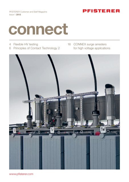
PFISTERER Customer and Staff Magazine<br />
Issue 1 2013<br />
4 Flexible HV testing<br />
6 Principles of Contact Technology 2<br />
16 CONNEX surge arresters<br />
for high voltage applications<br />
www.pfisterer.com
Legal Notice<br />
Publisher<br />
PFISTERER Kontaktsysteme GmbH<br />
Rosenstraße 44<br />
73650 Winterbach<br />
Germany<br />
Tel: +49 7181 7005 0<br />
Fax: +49 7181 7005 565<br />
info@pfisterer.com<br />
www.pfisterer.com<br />
Editorial Team:<br />
Reto Aeschbach, Peter Arranz<br />
Michael Bauer, Hagen Berroth<br />
Julia Faltin, Peter Feldhofer<br />
Norbert Fink, Hervé Gross<br />
Ruben Grund, Kurt Hosinger<br />
Eveline Jänicke, Peter Kaiser<br />
Martin Schuster, Barbara Simeon<br />
Christian Späth, Herwig Trost<br />
Frank Weichert, Lutz Zühlke<br />
Text Editor<br />
Karolina Kos<br />
www.xyzeiler.de<br />
4 Professional HV testing<br />
6 Contact Technology Principles 2:<br />
Theory into practice<br />
12 SICON for HV & large cables<br />
14 Practical tips: SICON Assembly<br />
15 Practical tips: 2DIREKT assembly<br />
16 Surge arresters for high<br />
voltage applications<br />
18 News<br />
Art Direction<br />
Vischer & Bernet GmbH<br />
Marketing and Advertising Agency<br />
www.vischer-bernet.de<br />
© Copyright by PFISTERER<br />
Kontaktsysteme GmbH<br />
PFISTERER<br />
Customer and<br />
Staff Magazine<br />
Issue 1 2013<br />
The QR codes in the magazine will take you to our website<br />
for further information on the relevant report.<br />
scan<br />
www<br />
1. Direct mobile<br />
phone at QR code<br />
2. Scan QR code<br />
3. Use information<br />
2 CONNECT 2013
Editorial<br />
Knowledge is value<br />
Dr. Thomas Klein<br />
Samuel Ansorge<br />
Jörg Fries<br />
Theory and practice bring the greatest<br />
benefits when they are combined – that’s<br />
our experience, and we will be reflecting<br />
that in this issue of CONNECT.<br />
On page 16 we present an example of<br />
the successful fusion of development and<br />
market requirements, the HV-CONNEX<br />
surge arrester, which brings multiple<br />
benefits as a flexible system component<br />
for high-voltage equipment.<br />
In the second part of our series of report<br />
on page 6, we explain the principles<br />
of contact technology, explaining how<br />
to apply basic knowledge to achieve<br />
conductor connections with a lifetime<br />
of four decades and more.<br />
We will be making it clear that correct<br />
assembly is essential to the life of a<br />
contact. We will be showing which tool<br />
is the best one to use for 2DIREKT<br />
terminals on page 15, and for SICON<br />
screw connectors on page 14.<br />
We hope that reading our magazine<br />
brings you many practical benefits.<br />
We aim provide the best service we<br />
can, every day.<br />
Sincerely,<br />
Dr. Thomas Klein Samuel Ansorge Jörg Fries<br />
PFISTERER Group Executive Committee<br />
CONNECT 2013<br />
3
HV testing of cable runs often have<br />
to be carried out under difficult<br />
conditions. PFISTERER is prepared<br />
for this. With unique test equipment<br />
that has already proven itself in<br />
sophisticated cable projects for<br />
offshore substations. Thanks to our<br />
forward-looking organization, we<br />
can meet different test situations.<br />
Whoever constructs turnkey high voltage cable systems<br />
will profit from a routine that excludes automatisms.<br />
PFISTERER has too. The company has been installing and<br />
testing high-voltage (HV) cable systems since 2008 and<br />
has again and again come up against complex limiting<br />
factors for which their Cable System Team has designed<br />
individual solutions – always in tight time frames and often<br />
on construction sites where many teams from the companies<br />
involved in the project are working in various trades at<br />
the same time.<br />
That was how it was when working on the “substation” on<br />
the Borkum West II offshore wind farm platform in July and<br />
August 2012. PFISTERER installed the cable connections<br />
for two gas-insulated switchgear units, which will receive<br />
the power from the surrounding wind turbines, each with<br />
an HV transformer that will convert the voltage from 33 kV<br />
to 155 kV for transmission to land via an undersea cable.<br />
Part of the acceptance tests for these cable systems was<br />
a high voltage test to IEC 60840.<br />
Prefabricated components make on-site high voltage testing easier.<br />
Complex conditions.<br />
Highly professional<br />
HV tests.<br />
4 CONNECT 2013
The required test voltage of 150 kV was generated by a<br />
test transformer that was transported to the site by truck.<br />
The challenge was to transmit the test voltage from the<br />
truck to the cable system. When working on offshore<br />
platforms, which initially take places in dry dock or while<br />
floating next to the wharf facility, the truck is usually not<br />
able to position itself sufficiently close to the cable system.<br />
PFISTERER has developed suitable test equipment for<br />
such situations, based on our own products, which are<br />
ideal for flexible test setups.<br />
Testing with a Plan<br />
At its heart is a test fixture with CONNEX open air bushings,<br />
which is transported to the site on a single axle trailer,<br />
positioned near the test transformer and connected to<br />
it via an overhead strand. The test voltage generated is<br />
transmitted via an HV rubber cable that is safe to touch.<br />
This is pre-assembled at both ends with a CONNEX<br />
connector, so it can be quickly connected via a CONNEX<br />
connector pre-installed in the test fixture and to the unit<br />
under test in a similar manner.<br />
The rubber cable is wound on a mobile cable drum, which<br />
serves as a transport medium and a laying device. The<br />
advantage of the rubber cable that so far only PFISTERER<br />
has used for test cable puposes: With a bend radius of five<br />
times the outer diameter, it is considerably more flexible<br />
than conventional XLPE cable – and that too at icy temperatures<br />
of down to −20 ° C. This facilitates the laying of the<br />
test cable round corners and in tight spaces.<br />
“However, apart from the equipment, what is important is<br />
having a forward-looking organization to work with,” says<br />
Lutz Zühlke, head of the Cable System team at PFISTERER,<br />
“That’s why we keep our customers informed of all the<br />
details that require their involvement right from the planning<br />
stage.” A glance at the PFISTERER report on the on-site<br />
testing of HV cable systems shows that the company takes<br />
into account all eventualities and thinks with the interests<br />
of its customers in mind.<br />
“Apart from the equipment,<br />
what is important is having a<br />
forward-looking organization<br />
to work with.”<br />
Lutz Zühlke, head of the Cable System team at PFISTERER<br />
A key component: The transition from the overhead line to<br />
the test cable – using a modular assembly made up of elements<br />
of the HV-CONNEX system.<br />
CONNECT 2013<br />
5
Long-lasting<br />
contacts,<br />
thanks to<br />
the right<br />
design &<br />
installation<br />
Knowledge is only useful when it is<br />
implemented. This second report on<br />
the principles of contact technology<br />
demonstrates, with the aid of terminals<br />
that have been in service for a<br />
long time, how the life expectancy<br />
of conductor connectors can be improved,<br />
with lifetimes of up to four<br />
decades and longer being achieved,<br />
despite the natural aging of the contact.<br />
The preconditions for this are<br />
that the connectors are designed<br />
according to the right principles and<br />
are installed correctly.<br />
The general rules for the design of a connector are wide<br />
and varied and the trade-offs are complex, as demonstrated<br />
by the following design principles. On the one hand,<br />
the design must ensure specific contact properties are adhered<br />
to under all operating conditions, while on the other,<br />
production costs must remain within acceptable limits.<br />
Fulfilling both rules confronts the manufacturer with diverging<br />
requirements, even when he is selecting materials:<br />
Steel, for example, is cheaper than aluminum. Moreover,<br />
with a stronger steel clamp, the required initial force to<br />
contact a conductor can be produced more easily than<br />
with an aluminum clamp. However, taking account of the<br />
need for a durable connection, steel loses its appeal: Steel<br />
connectors offer a higher resistance to current as it flows<br />
through the contact points. The result: Higher temperatures,<br />
that promote the aging of the contact (for details see<br />
Part 1, CONNECT 1/2012).<br />
The choice of materials also depends on the need to prevent,<br />
as far as possible, a permanent mechanical deformation<br />
of the connector body when the contact is being made.<br />
Doing so would affect the mechanical functions of the<br />
terminal and speed up the processes of creep, flow and<br />
settling which weaken the contact (for details see Part 1,<br />
CONNECT 1/2012). Another important factor is the length,<br />
thickness and width of the connector components – with<br />
the right choice, the required contact force can be achieved<br />
without permanent plastic deformation of the connector<br />
body. And even with metallic coatings, it is important to<br />
find the right balance: The coating thickness and material<br />
must be chosen so that electrical properties such as low<br />
contact resistance can be achieved, there is a corrosion<br />
protection effect and costs remain reasonable.<br />
6 CONNECT 2013
Tolerances without tolerance<br />
The sophisticated interaction of materials and design is<br />
manifested most clearly in the central factors of contact<br />
force and resilience. The contact force must be large<br />
enough to minimize the initial resistance that exists when<br />
the contact is made. Furthermore, suffi cient contact force<br />
must remain throughout the entire life of the connection<br />
and the temperature-induced elongation of the conductors<br />
must be held in check, otherwise this will lead to micromovements<br />
between the conductor and the contact parts,<br />
leading to mechanical abrasion and fretting and eventually<br />
to contact failure (see Part 1, CONNECT 1 / 2012).<br />
At the same time the material and design should be such<br />
that the system can “breathe thermally”. When heated,<br />
aluminum expands more than other metals. Result: If aluminum<br />
conductors are connected with a “rigid” copper or<br />
steel clamp, they do not have enough space to stretch,<br />
the conductor fl ows away but does not return to its original<br />
shape on cooling. Over several heating and cooling cycles,<br />
the electrical contact degrades gradually until total failure<br />
occurs.<br />
To master this balancing act between force and fl exibility,<br />
contact equipment manufacturers need to learn to understand<br />
stretching, as there has been a widespread replacement<br />
of copper conductors by aluminum conductors.<br />
In the time of this changeover, PFISTERER developed the<br />
V-terminal with integrated resiliency – then a novelty, now a<br />
standard product. It allows for thermal breathing, fi rstly<br />
by using aluminum for the clamping body, as aluminum<br />
conductors and the terminal body have the same thermally<br />
induced expansion behavior (inherent elasticity). Secondly,<br />
the clamping body is deformed as the screw is tightened<br />
at defi ned points so that elastic deformation occurs, which<br />
acts like a pre-stressed spring (design elasticity). Confi guring<br />
the way in which contacts are made provides suffi cient<br />
contact force using screw technology, which also prevents<br />
the longitudinal movement of the conductor in the terminal.<br />
Figure 1: Ideal arrangement of the contact elements: Donati’s rule of current commutation shows that<br />
the current density of a connection is not the same at all points: The commutation takes place for the most part<br />
at the beginning and at the end of the overlapping surfaces of the conductors. Ergo: The contact areas (zones,<br />
lines, points) are placed as close as possible to the beginning or end of the clamp.<br />
CONNECT 2013<br />
7
Optimum force. Suboptimal results?<br />
Another fi nding: Suffi cient contact force is not enough.<br />
For example, when aluminum is used, it oxidizes easily.<br />
<strong>Here</strong>, the contact zone must be designed so that the<br />
non-conductive oxide layers of the contact edges or teeth<br />
are penetrated. This method results in a purely metallic<br />
contact, ensuring the unhindered fl ow of current from one<br />
conductor to another. Another important criterion is the<br />
arrangement of the contact edges or teeth in the terminal<br />
area. The Donati rule for current commutation shows<br />
that they should ideally be positioned where the natural<br />
commutation is highest (see Figure 1).<br />
And sometimes optimal force is too much force. For<br />
example, when spring washers are inserted between the<br />
screw and the connector body, bringing elasticity. Where<br />
connectors are made of aluminum or plastic, this effect is<br />
removed if the installation has been carried out incorrectly:<br />
When the screw is tightened, it creates a high pressure<br />
load on a relatively small area, and under the tightening<br />
pressure, the spring washer located here burrows into the<br />
“soft” connector body, so that the required spring function<br />
is lost. The only solution in this situation is to place a fl at<br />
steel washer between the connector body and the spring<br />
washer. This distributes the force over the entire contact<br />
area and prevents the washer sinking in (see Figure 2).<br />
Correct installation – lower risks<br />
And even when the vital elasticity is present through<br />
design, installation errors can endanger the long-term<br />
stability of the contact. One rule for installation is: Remove<br />
contamination and oxide layers on the contact areas by<br />
cleaning and brushing. In addition, use contact greases or<br />
pastes – especially under critical environmental conditions.<br />
They protect the actual contact zones against the ingress of<br />
air, water and salt and thus against oxidation and corrosion.<br />
Added to this is that in the case of bolted connections,<br />
it is only the proper lubrication of the screw that can ensure<br />
the optimal conversion of the applied torque into the<br />
required contact force. How signifi cant the loss of force<br />
can be when the grease is forgotten or wrongly applied<br />
can be seen in table 1.<br />
Careful preparation means that electrical<br />
contact can be maintained for decades.<br />
Contact protection paste prevents the<br />
oxidation of the points of contact.<br />
Figure 2 shows a classic installation error:<br />
1. A spring washer is inserted<br />
between the screw head<br />
and a connector body made<br />
of aluminum or plastic.<br />
2. Under the tightening pressure,<br />
the screw sinks into the „soft“<br />
connector body and loses its<br />
resilience<br />
3. Solution: a fl at steel washer is placed<br />
between them (3). It distributes the initial<br />
force that has been introduced over a wider<br />
area and prevents the screw from sinking in.<br />
8 CONNECT 2013
Since installation is often carried out under difficult conditions<br />
and with time constraints, manufacturers of contact<br />
technology endeavor to eliminate installation errors through<br />
suitable connector designs, or at least minimize their<br />
consequences. So, for example, some manufacturers only<br />
supply pre-greased screws. Another method is giving<br />
a metallic coating to the terminals or contact zones. Tin<br />
coatings are an economic solution that provides added<br />
reliability, if insufficient cleaning and greasing has been<br />
carried out. When penetrated by the contact teeth, the waxy<br />
tin retreats and closes up around the contact points again<br />
after the contact has been made. The electroplating<br />
process may automatically remove any oxide layer that may<br />
be present on aluminum surfaces.<br />
Many findings – one clamp<br />
The implementation of these and other findings were already<br />
carried out in the 1960s in the ABC tapping clamps from<br />
PFISTERER (Figure 3): The application-specific matching<br />
of screw, screw greasing and torque results in the required<br />
initial force being achieved. When tightening the screw, the<br />
contact teeth bite into the conductor insulation and the<br />
conductor, thus creating defined, bare contact points. The<br />
shape of the metallic contact plates (elasticity) guarantees<br />
a permanent contact force. Contact plates are tin plated to<br />
create improved and reliable contacts with slightly oxidized<br />
aluminum conductors.<br />
Figure 3: Even in ABC branch terminal from the 1960s, all the design criteria for modern terminals were taken account of.<br />
CONNECT 2013<br />
9
The contact plates are embedded in a plastic connector<br />
body, reducing costs and improving reliability. In addition,<br />
a steel plate is integrated.into the connector body directly<br />
below the screw heads. Without this, the plastic body<br />
would be exposed to excessively high mechanical loads in<br />
the small area under the screw head. This design is still<br />
the basis for more advanced tapping terminals such as the<br />
ISICOMPACT from PFISTERER, where the pressure plate<br />
is also designed to act as a spring element.<br />
One specification – many parameters<br />
The construction principles illustrated by the ABC tapping<br />
terminal are used in many design rules, which are refl ected<br />
in the specifi cations of both manufacturers and users. The<br />
long term transmission capability of a contact, for example,<br />
is often defi ned by the initial force that has to be applied to<br />
produce the connection, or over the length of the existing<br />
lines of contact, or the surface of the contact points that<br />
have been created.<br />
One user specifi cation, for example, calls for a 120 kN initial<br />
force to be transmitted per ampere at a conductor capacity<br />
of 1000 A in the terminal of an outdoor switching station.<br />
In order to meet this, the manufacturer must take account<br />
of the various infl uences that affect one another, such as<br />
the materials used for the screw, nut and washer, their<br />
surface characteristics (uncoated, galvanized, greased),<br />
the pitch of the screw thread, the number of screws and<br />
the tightening torque.<br />
From initial values to the design<br />
This process is carried out with the help of a table of<br />
empirical data. Starting with a standard screw made of hot<br />
dip galvanized steel, size M12 and strength category 8.8<br />
results in a nominal torque of 80 Nm (see Table 2), which<br />
is incorporated as a neutral factor of 8.0 in the calculation<br />
of the design of a screw connector.<br />
If an aluminum nut and A-2 washer are chosen, this combination<br />
of materials gives a required initial force equal<br />
to the clamping force of 3.8 kN per 10 Nm of tightening<br />
torque, for a thread greased with Vaseline (see Table 3).<br />
Multiplying these two values gives an initial force of<br />
30.4 kN per screw. To achieve the required 120 kN,<br />
four screws are used, which results in 121.6 kN, meeting<br />
the specifi cation.<br />
Fine tuning and innovation<br />
It is different if the user requests the use of screws in steel<br />
group A2 or A4 and the strength category 80. An average<br />
tightening torque of 75 Nm is allocated to them (Table 2).<br />
So with the same nut and washer material, four screws<br />
would reach a clamping force of 3.8 kN per 10 Nm of<br />
tightening torque (Table 3), so “only” 114 kN.<br />
For an experienced designer this is no problem, because<br />
every parameter includes a tolerance. In this case, the<br />
missing 6 kN can be achieved by using another grease<br />
that converts the torque into the required clamping force<br />
even more effi ciently than Vaseline. Innovative manufacturers,<br />
however, claim to have moved beyond this. In addition<br />
to the principles mentioned here, their latest generation<br />
of connectors achieve even greater effi ciency with higher<br />
safety and greater fl exibility in use.<br />
10 CONNECT 2013
Contact forces from screws<br />
Screw<br />
Greasing<br />
Force in kN at a torque of<br />
56 Nm 80 Nm<br />
A2 F70<br />
A2 F70<br />
A2 F70<br />
without<br />
Vaseline<br />
M 50 G<br />
21.8<br />
19.8<br />
29.3<br />
28.6<br />
27.4<br />
39.6<br />
8.8 hdg<br />
8.8 hdg<br />
8.8 hdg<br />
without<br />
Vaseline<br />
M 50 G<br />
17.1<br />
24.8<br />
21.9<br />
25.7<br />
31.7<br />
32.1<br />
8.8 electroplated tin<br />
8.8 electroplated tin<br />
8.8 electroplated tin<br />
without<br />
Vaseline<br />
M 50 G<br />
18.9<br />
32.5<br />
29.4<br />
22.9<br />
47.0<br />
43.0<br />
Table 1 reveals details that have a big impact: If there is a failure to lubricate the screw or it is performed incorrectly, the torque introduced cannot be sufficient<br />
to create the required contact force. Result: A loss of force of up to over 50%.<br />
Tightening torques<br />
Thread<br />
Tightening torques for screw material in Nm<br />
• Unalloyed or alloyed steels<br />
• Rust and acid resistant steels,<br />
• R P 0.2 MIN. = 640 N/mm 2 • R P 0.2 MIN. = 600 N/mm 2<br />
hot dip galvanized (hdg)<br />
• Strength category 8.8<br />
steel group A2 or A4<br />
• Strength category 80<br />
M 6<br />
M 8<br />
M 10<br />
M 12<br />
M 14<br />
M 16<br />
M 18<br />
M 20<br />
9.5<br />
23<br />
46<br />
80<br />
125<br />
195<br />
280<br />
390<br />
9<br />
22<br />
43<br />
75<br />
120<br />
180<br />
260<br />
370<br />
Table 2 summarizes the tightening torques for different screw materials.<br />
Clamping forces in kN for each 10 Nm of tightening torque, thread greased with Vaseline<br />
Screw Nut Washer M8 M10 M12 M16<br />
St hdg<br />
St hdg<br />
St hdg<br />
St hdg<br />
A2 /A4<br />
A2 /A4<br />
A2 /A4<br />
St<br />
Al<br />
Al<br />
Cu / Rg / Ms<br />
St<br />
A2 / A4<br />
Al<br />
St hdg<br />
St hdg<br />
A2<br />
St hdg<br />
A2 / A4<br />
A2 / A4<br />
A2 / A4<br />
4.5<br />
4.8<br />
5.7<br />
4.5<br />
4.3<br />
4.1<br />
4.3<br />
3.6<br />
3.8<br />
4.5<br />
3.6<br />
3.4<br />
3.3<br />
3.4<br />
3.0<br />
3.2<br />
3.8<br />
3.0<br />
2.9<br />
2.8<br />
2.9<br />
2.3<br />
2.5<br />
2.9<br />
2.3<br />
2.2<br />
2.1<br />
2.2<br />
Table 3 gives the required clamping forces for selected combinations of materials as a function of tightening torque for a thread greased with Vaseline.<br />
CONNECT 2013<br />
11
Large cables.<br />
High voltage.<br />
All under<br />
control<br />
with SICON.<br />
SICON screw connectors are increasingly<br />
used in the high voltage<br />
range and with large cable crosssections.<br />
And for good reason: the<br />
new connection concept brings<br />
many application opportunities<br />
and advantages compared to the<br />
compression method. This is not<br />
only appealing to users and installers.<br />
Other manufacturers of cable<br />
accessories are using SICON as a<br />
standard component.<br />
Anyone who is connecting up large cable cross sections<br />
using compression technology knows the pitfalls of this<br />
method. The larger the cross-section, the larger and<br />
heavier the compression machine and the press tools,<br />
the latter weighing in at up to 100 kilos. They are therefore<br />
diffi cult to handle on site. When crimping terminals, the<br />
crimping tools often need to be hoisted by crane onto the<br />
mast cross arm. When working underground, it is often<br />
tight in two locations: Cable trenches provide hardly any<br />
room to move, and there are few places to position the<br />
crimping tool.<br />
There are many better alternatives provided by PFISTERER,<br />
for example SICON head armatures for cable terminations<br />
and SICON connectors for underground and aboveground<br />
cable connections. The SICON connectors are constructed<br />
to be used with commercially available joints, so that their<br />
outer diameter corresponds to that of the cable insulation.<br />
The benefi t is that the joint can be easily pushed over<br />
the connector. In addition, there is no need for stress relief<br />
devices. These are used to cover any sharp edges that<br />
may result from crimping.<br />
Because of the fi xed relationship between the compression<br />
sleeve and the conductor diameter as regards size and<br />
material, crimping tools are also less fl exible in use – a<br />
disadvantage, in view of the diversity in the world’s power<br />
grids. With SICON screw connectors, it is different. Each<br />
variant serves several conductor diameters with just one<br />
connector. And more: For the fi rst time, with SICON,<br />
PFISTERER has succeeded in achieving the defi ned contact<br />
forces independently of the conductor material and<br />
surface treatment.<br />
SICON screw connectors are also suitable for use on HV cable terminations.<br />
12 CONNECT 2013
Ideal force for many conductors<br />
An important step forward, in particular when expanding<br />
a network, is that it is not possible to predict which conductor<br />
material will be encountered and the extent to which<br />
the surface is oxidized. The friction that results from making<br />
a contact, also known as the coeffi cient of friction, strongly<br />
infl uences the proportion of the applied torque that is converted<br />
into contact force. To ensure there is always suffi cient<br />
contact force, in all SICON connectors PFISTERER uses<br />
stepless shear bolts with integral pressure plates.<br />
During the decisive last few turns, the pressure plate causes<br />
the screw to turn on the plate and not on the conductor.<br />
The effect is that the friction coeffi cient of the conductor<br />
does not affect the contact force that is generated. The<br />
frictional forces between the screw and the pressure plate<br />
are, however, a known quantity to the manufacturer, as it<br />
has been predefi ned with both the material and greasing.<br />
Thus using the design parameters of the screw, the contact<br />
force can be adjusted very accurately according to the<br />
torque. Thanks to the stepless design of the patented<br />
SICON bolts, they only shear off when the predefi ned<br />
torque is reached. The shearing off takes place without<br />
any protrusions from the screws being left behind, which<br />
eliminates time-consuming fi ling.<br />
High acceptance, new applications<br />
These and other benefi ts explain SICON’s high market<br />
acceptance. After almost ten years of success in the<br />
medium voltage range, PFISTERER has gradually applied<br />
this connection concept to high voltage applications.<br />
The latest product is the standard version of IXOSIL joints<br />
and terminations with the IEC 61238 certifi ed SICON XXL<br />
version for up to 2,500 mm². Joints equipped with SICON<br />
have passed many customer- specifi c type tests.<br />
“Furthermore, positive customer<br />
feedback and use by other<br />
cable accessory manufacturers<br />
has confi rmed the SICON<br />
connector concept,” said<br />
Martin Schuster, Senior Advisor<br />
at PFISTERER, “And whoever<br />
carries out the calculations<br />
comes to the conclusion that<br />
the initial extra cost for screw<br />
connector is quickly compensated<br />
for by taking into account<br />
the required investment in<br />
various presses and crimping<br />
tools and the associated maintenance<br />
costs.”<br />
Martin Schuster, Senior Advisor at PFISTERER<br />
SICON connectors: conductor cross sections up to 2,500 mm² with SICON XXL for high voltage joints.<br />
CONNECT 2013<br />
13
PRACTICAL TIP:<br />
Impact wrenches<br />
for SICON installation<br />
Many users prefer a battery operated impact screwdriver<br />
for installing screw connectors. But they are not all suitable.<br />
Because to use them correctly, there are many criteria<br />
that must be considered: Torque, pulse frequency, battery<br />
capacity, hammer mechanism and more. Furthermore, the<br />
tool inserts must be of the right quality.<br />
In order to facilitate the proper selection, PFISTERER has<br />
tested various impact wrenches to assess their suitability.<br />
The following overview shows which wrenches have been<br />
specifically approved for fitting SICON screw connectors<br />
and terminations, and some of the suppliers from where<br />
you can obtain them.<br />
Suitable impact wrenches<br />
Impact<br />
screwdriver<br />
Manufacturer<br />
Distributed by,<br />
for example<br />
C 18 IW Milwaukee PFISTERER<br />
Furthermore, only those tool inserts should be used that<br />
are approved for use with impact screwdrivers – so-called<br />
“impact sockets”. These differ from standard “ratchet sockets”<br />
as follows:<br />
• One piece construction using special steel<br />
and manufactured in one piece<br />
• Safety holder: Bore and ball groove or safety ring<br />
• Square drive as per DIN 3121, ISO 1174 - G 12.5 (½")<br />
And for easy handling, here are two important installation<br />
tips from PFISTERER: Where a screw cannot be removed<br />
with a motor driven tool – for example, because the tool is<br />
worn or there is insufficient power – the following approach<br />
should be used: Installation should be completed with a<br />
tool that can be operated manually.<br />
Whether using a manual or a battery operated impact<br />
wrench, under no circumstances use a socket wrench<br />
extension. The risk is that the screw breaks off earlier<br />
than it should. This results in the defined torque not being<br />
reached, and therefore the contact force needed to<br />
produce a contact that will have a long service life is also<br />
not achieved.<br />
IT 10000-033 Hitachi TE connectivity<br />
ASKO Compact<br />
BTW 250 RFE<br />
ASKO Compact<br />
BTW 151 RJEX<br />
Makita<br />
Makita<br />
Nexans Power<br />
Accessories<br />
Germany GmbH<br />
Nexans Power<br />
Accessories<br />
Germany GmbH<br />
Further details can be downloaded<br />
in the summary of these installation<br />
tips on the PFISTERER website:<br />
www.pfisterer.com<br />
Only certain impact wrenches are suitable<br />
for the installation of shear off bolts.<br />
14 CONNECT 2013
PRACTICAL<br />
TIP:<br />
2DIREKT<br />
installation<br />
easily and<br />
safely<br />
Proper installation requires proper tools. It is the same<br />
when you are connecting 2DIREKT transformer terminals:<br />
When tightening the clamping screws the transformer<br />
terminal must be fixed. Gripping with a pipe wrench is<br />
strongly discouraged, as it will damage the surface of the<br />
2DIREKT terminal.<br />
A simple solution is to use a counter-holder made of wood<br />
or plastic in the screw hole – a hammer shaft is usually<br />
suitable. A professional solution that can be created by any<br />
user, and one which PFISTERER discovered together with<br />
a customer, is a bolt turned from fiberglass-free plastic<br />
(the white bolt in the picture) that fits into the conductor<br />
hole and can be easily and safely used as a lever.<br />
PFISTERER would be pleased to send you the<br />
technical drawing of this on request. Just contact<br />
us at info@pfisterer.com, keyword “2DIREKT”.<br />
Save the date 2013.<br />
TRANSFORM campus:<br />
All about transformers.<br />
6–7 June 2013, Scandic Hotel Berlin<br />
Content of the seminar<br />
• Expert knowledge about the grid and<br />
transformers from the field and first-hand<br />
• Technical sessions on various transformer<br />
components<br />
• Q&A, discussion and networking<br />
HIGH VOLTAGE: Spectacular show and<br />
live testing of high voltage transformers<br />
For whom<br />
• Young engineers at the start of their careers<br />
• Newcomers to the transformer industry<br />
• Anybody who wants to know more about<br />
transformer principles in general<br />
Use this unique opportunity<br />
Register for the campus and visit us at<br />
CWIEME Berlin 4 – 6 June 2013!<br />
We’re looking forward to seeing you!<br />
Register now! www.transform.net<br />
www.pfisterer.com<br />
THE POWER CONNECTION
HV-CONNEX:<br />
Safe from surge<br />
NEW: NOW UP TO 145 KV<br />
PFISTERER is completing the<br />
CONNEX cable connector system<br />
with HV-CONNEX size 4 (up to<br />
72.5 kV) and 5-S (up to 145 kV)<br />
surge arresters, providing a system<br />
solution that brings multiple<br />
benefits for the high-voltage range:<br />
Solid insulated and pluggable,<br />
these arresters make it possible<br />
to achieve the optimum surge<br />
protection design for transformers<br />
and gas-insulated switchgear (GIS).<br />
Every transformer is designed for surges – up to the limit,<br />
allowed by its practical and economic design. However,<br />
in operation, there are frequently surges that threaten to<br />
exceed these design values. The most common causes<br />
are lightning strikes or the abrupt switching of a GIS at full<br />
load. This results in transient surges that can reach several<br />
million volts and overload the coils inside a transformer,<br />
and at worst, can destroy it mechanically. A common antidote<br />
is an arrester, which takes up the surge and converts<br />
it to heat.<br />
Protection at the Hot Spot<br />
Not only that. Transient surges propagate as traveling<br />
waves. Although they diminish with each meter traveled,<br />
they can also increase as a result of superimposed refl ections<br />
where there are changes in the line impedance, such<br />
as at the transition point from the overhead line to a bushing<br />
or a cable termination. Thus the traveling wave nature<br />
of transient surges limits the protected zone offered by<br />
arresters. This means that optimal protection is achieved<br />
when the arrester is installed directly on the transformer<br />
that needs protection or directly on the GIS, from which a<br />
surge may start.<br />
Air-insulated or gas-insulated arresters are in widespread<br />
use. The former require a lot of space because of the<br />
striking distances required and the necessary mounting<br />
structures. A solution that is hardly feasible in urban areas.<br />
Gas insulated arresters in turn have a negative effect<br />
on the SF 6 gas footprint. Installation involves expensive<br />
oil and gas work that must be carried out by specialized<br />
professionals, and connecting them requires an additional<br />
connection to tap the high voltage potential.<br />
The design of a surge arrester is complex as it depends on<br />
many factors, including the earthing system, the distance<br />
between the arrester and the equipment that needs protection,<br />
the anticipated surge and the network topology.<br />
<strong>Here</strong>, clear parameters come up against unknown factors.<br />
Although there are statistical studies concerning the<br />
regional occurrence and frequency of certain types of<br />
lightning, the question remains: Where exactly will which<br />
lightning strike actually hit and with how much energy?<br />
HV CONNEX surge arrestors installed in a power transformer.<br />
16 CONNECT 2013
CONNEX. One system. Many benefits<br />
Plug-in HV-CONNEX surge arresters are different: Their<br />
insulation and fi eld control consists of solid silicone, so no<br />
environmentally damaging liquids or insulating gases are<br />
involved. Where there is no internal gas pressure, there are<br />
also no pressure vessel regulations to be observed, and<br />
gas monitoring is not required. The solid insulation also<br />
allows a compact, space-saving design to be employed.<br />
Other benefi ts of the pluggability of the CONNEX system:<br />
If the cable connecting sockets are pre-installed on the<br />
device-side, there is no need for oil or gas work when<br />
connecting via the cable-side connector. This allows transformers<br />
and GIS to be pretested by the manufacturer<br />
before delivery.<br />
The connector system also makes it easier to remove the<br />
surge arrester quickly and easily, for example after a short<br />
circuit due to overloading or when performing a dielectric<br />
test on the transformer. If the installation is positioned<br />
suitably, the socket can also be used for insertion of a test<br />
device. Last but not least, the combination of solid insulation<br />
and pluggability results in the CONNEX system offering<br />
complete protection against contact and is maintenance<br />
free – a safety plus for humans and animals, as the wiring<br />
is protected from the elements. The bottom line: The ideal<br />
solution for connecting transformers and GIS.<br />
At a glance:<br />
HV-CONNEX surge arrester<br />
sizes 4 & 5-S<br />
For protection of metalclad switchgear and transformers<br />
which are fi tted with plug-in connections in accordance<br />
with EN 50180 / 50181.<br />
Possible applications:<br />
• Connecting a transformer via a cable line<br />
to the overhead line<br />
• Connecting switchgear via a cable to<br />
the overhead line<br />
• Connecting a switchgear via a cable<br />
to other resources<br />
• Voltage levels up to U m = 72.5 kV or<br />
U m = 145 kV<br />
• Max rated voltage U R = 72.5 kV<br />
or U R =145 kV<br />
Features & Benefits<br />
Power transformers using<br />
HV CONNEX surge arrestors need<br />
only a limited installation area.<br />
• Active part constructed with no spark gaps,<br />
using metal-oxide resistors without spark gaps<br />
• Resistors with high thermal stability<br />
• Corrosion-resistant and shock proof thanks to<br />
aluminum and fiberglass housings, so also<br />
• Hermetic encapsulation of the active components<br />
against environmental influences such as humidity<br />
or pollution<br />
• Insulation of the active parts from the metallic<br />
housing by means of silicone rubber sheathing<br />
• Maintenance-free, as solid insulated<br />
• Outdoor resistant<br />
• Any mounting position<br />
• Plug-in<br />
• Bursting disc with rotatable exhaust port for defined<br />
pressure relief in the event of overload<br />
New HV CONNEX surge arrestors<br />
now also available at up to 145 kV<br />
operating voltage.<br />
More information on the<br />
PFISTERER website:<br />
www.pfi sterer.com<br />
CONNECT 2013<br />
17
News<br />
HV-CONNEX connectors:<br />
3 new variants for thicker<br />
insulation<br />
HV-CONNEX corner joint:<br />
For simple HV testing<br />
For on-site testing of HV cable runs or HV systems, test joints are<br />
used which are connected to the device under test on one side<br />
and to a bushing on the other, through which the test voltage is<br />
applied. With straight test joints, the layout of the bushing is often<br />
horizontal. The disadvantage is that the bushing is too close to<br />
the ground to meet the clearance requirements, and a complex<br />
substructure is needed.<br />
It is much simpler with the HV-CONNEX corner joint for up to<br />
245 kV from PFISTERER. Thanks to the arrangement of its two<br />
connectors at a 90-degree angle to each other, the bushing can<br />
vertical and set up accordingly, so it is not close to the ground<br />
and substructures are no longer needed.<br />
The HV-CONNEX cable connection system is<br />
following the trend of thicker cable insulation: After<br />
the introduction of the CONNEX connector variants<br />
in sizes 2, 3 and 3-S that meet this requirement,<br />
PFISTERER is now supplying sizes 4, 6 and 6-S<br />
with a modifi ed insulator.<br />
With the new CONNEX connector variant in size 4,<br />
cables with a diameter of up to 78.5 mm over<br />
insulation and a cross-section of up to 1,600 mm 2<br />
can be connected. Such cables are to be found in<br />
several regions of the world, such as France, parts<br />
of North Africa and the USA.<br />
The new CONNEX connector variants in size 6 cover<br />
cables with a diameter up to 113.5 mm over insulation<br />
and a cross section of up to 2,500 mm 2 – a type<br />
of cable that is increasingly common, in particular<br />
in Russia and Asian countries.<br />
Silicone Composite Insulators –<br />
a book for professionals<br />
In the book “Silicone Composite Insulators”, authors Dr. sc. ETH Konstantin<br />
O. Papailiou and Dr. Frank Schmuck have summarized nearly 40-years of<br />
experience with PFISTERER SEFAG with overhead lines and in particular with<br />
the silicone composite insulator products. The reference book provides a<br />
comprehensive introduction as well as being a reference work for practitioners.<br />
The English version is now available (Springer, 495 pp., 484 illustrations,<br />
ISBN 978-3-642-15320-4).<br />
18 CONNECT 2013
PFISTERER –<br />
Top Partner for Siemens<br />
2DIREKT: Contact protection<br />
with fixed ball point<br />
PFISTERER has long been a trusted supplier to<br />
Siemens AG. The company’s status as a “Preferred<br />
Supplier” was recently confirmed by the inclusion<br />
of PFISTERER in the “Forward Procurement List” of<br />
Siemens’ top suppliers, a list that includes many<br />
well-known corporations. The conditions for inclusion<br />
include high quality, the strategic importance of the<br />
products and key account management.<br />
Inclusion on the FP list not only reaffirms vendor<br />
status but also deepens the partnership between<br />
Siemens and its suppliers. Siemens supports<br />
its partners in, for example, implementing energy<br />
efficiency measures.<br />
When working on distribution transformers, they must be shortcircuited<br />
and earthed in accordance with the five safety rules.<br />
The earthing and short-circuiting kit is easy to connect to the fixed<br />
ball point (see upper picture), which is positioned on the pressure<br />
screw of the 2DIREKT transformer terminals.<br />
For the contact protection coverage of the fixed ball point as well,<br />
before and after maintenance, PFISTERER now supplies the new<br />
earthing hood cover made of transparent plastic as an accessory<br />
to the well-known black 2DIREKT cover.<br />
This can be easily opened with an insulating pole from a safe<br />
distance so that you can easily reach the protruding fixed ball<br />
point for connecting the earthing device from all sides.<br />
Once maintenance is complete, the earthing hood cover can just<br />
as easily closed again with the insulating pole and all the live parts<br />
of the 2DIREKT transformer connection are covered and touch<br />
safe when in operation, including the fixed ball point (see picture<br />
below).<br />
Norbert Fink,<br />
Key Account manager at PFISTERER<br />
for Siemens.<br />
CONNECT 2013<br />
19
Save the date 2013.<br />
TRANSFORM: The international<br />
conference for specialists from<br />
the transformer industry.<br />
TRANSFORM Americas<br />
Cartagena de Indias<br />
Conference and Exhibition<br />
28 – 30 July 2013<br />
Hilton Hotel Cartagena, Colombia<br />
We’re looking forward to seeing you!<br />
Register now! www.transform.net<br />
TRANSFORM Abu Dhabi<br />
Conference and Exhibition<br />
26 – 28 November 2013, YAS Viceroy<br />
Abu Dhabi, United Arab Emirates<br />
www.pfisterer.com<br />
The power connection