
Create successful ePaper yourself
Turn your PDF publications into a flip-book with our unique Google optimized e-Paper software.
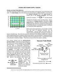
<strong>Review</strong> <strong>of</strong> <strong>Geometric</strong> <strong>Optics</strong><br />
1.The ray approximation; Reflection; Refraction; Snell’s law <strong>of</strong><br />
refraction; Dispersion; Total Internal Reflection.<br />
2. Images formed by flat mirrors<br />
3. Images formed by Spherical Mirrors<br />
4. Images formed by Refraction<br />
5. Thin Lenses
• 1.The ray approximation: A wave moving through a medium<br />
travels in a straight line in the direction <strong>of</strong> its rays, which are<br />
perpendicular to the wave front.<br />
• The law <strong>of</strong> reflection: The angle <strong>of</strong> reflection equals the angle <strong>of</strong><br />
incidence.<br />
• The Snell’s law <strong>of</strong> refraction: n 1 *sin q 1 = n 2 * sin q 2<br />
• Dispersion: The index <strong>of</strong> refraction varies with the wavelength <strong>of</strong><br />
the light passing through the material.<br />
• Total Internal Reflection:<br />
sin q c =n 2 /n 1 , q 2 = 90 ( for n 1 >n 2 )
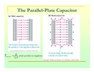
Images are classified as real or virtual.<br />
A real image is formed when<br />
light rays pass through and<br />
diverge from the image<br />
point.<br />
A virtual image is formed<br />
when the light rays do not<br />
pass through the image point<br />
but appear to diverge from<br />
that point.
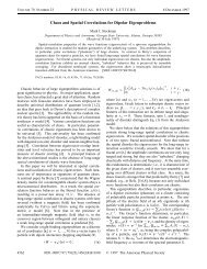
Images formed by flat mirrors<br />
p- the object distance<br />
q- the image distance<br />
Because the triangles PQR and<br />
P’QR are congruent, and p = q,<br />
h = h’.<br />
Lateral magnification :<br />
M<br />
≡<br />
Im age height<br />
Object height<br />
=<br />
h'<br />
h
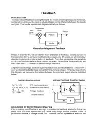
Images formed by Spherical Mirrors<br />
• A spherical mirror has the shape <strong>of</strong> a section <strong>of</strong> a sphere.<br />
• A concave mirror: light is reflected from the inner surface.
Images formed by Spherical Mirrors<br />
A concave mirror<br />
• Center <strong>of</strong> curvature;<br />
• Principal axis;<br />
• paraxial rays.
Images formed by Spherical Mirrors<br />
A concave mirror
Images formed by Spherical Mirrors<br />
A concave mirror<br />
tanθ<br />
h q<br />
M = ' = −<br />
h p<br />
tanα<br />
1 1 2<br />
+ =<br />
p q R
Images formed by Spherical Mirrors<br />
A concave mirror
Images formed by Spherical Mirrors<br />
A concave mirror<br />
• F- focal point; f- focal length<br />
1 R ≈ 0 q ≈<br />
p 2<br />
f =<br />
R<br />
2
Images formed by Spherical Mirrors<br />
A concave mirror<br />
• F- focal point; f- focal length<br />
f =<br />
R<br />
2
Images formed by Spherical Mirrors<br />
A convex mirror: light is reflected from the outer, convex surface.<br />
The front<br />
side and the<br />
back side <strong>of</strong><br />
the mirror.<br />
A diverging mirror: the image is virtual, upright and smaller.
Images formed by Spherical Mirrors<br />
A convex mirror: light is reflected from the outer, convex surface.<br />
Mirror equation:<br />
1<br />
p<br />
+<br />
1<br />
q<br />
=<br />
1<br />
f
A convex mirror:<br />
The same mirror equation:<br />
1<br />
p<br />
+<br />
1<br />
q<br />
=<br />
1<br />
f<br />
Pay Attention to signs!
Ray Diagrams for Mirrors<br />
Special rays help to find the positions and sizes <strong>of</strong> images.<br />
Ray 1 is drawn from the top <strong>of</strong> the object parallel to the<br />
principal axis and is reflected through the focal point F.<br />
Ray 2 is drawn from the top <strong>of</strong> the object through the<br />
focal point and is reflected parallel to the principal axis.<br />
Ray 3 is drawn from the top <strong>of</strong> the object through the<br />
center <strong>of</strong> curvature C and is reflected back on itself.
Ray Diagrams for Concave Mirrors<br />
Ray 1 is drawn from the top <strong>of</strong> the<br />
object parallel to the<br />
principal axis and is reflected<br />
through the focal point F.<br />
Ray 2 is drawn from the top <strong>of</strong> the<br />
object through the<br />
focal point and is reflected parallel<br />
to the principal axis.<br />
Ray 3 is drawn from the top <strong>of</strong> the<br />
object through the<br />
center <strong>of</strong> curvature C and is<br />
reflected back on itself.<br />
When the object is located so that the center <strong>of</strong><br />
curvature lies between the object and a concave<br />
mirror surface, the image is real, inverted, and<br />
reduced in size.
Ray Diagrams for Concave Mirrors<br />
Ray 1 is drawn from the top <strong>of</strong> the<br />
object parallel to the<br />
principal axis and is reflected<br />
through the focal point F.<br />
Ray 2 is drawn from the top <strong>of</strong> the<br />
object through the<br />
focal point and is reflected parallel<br />
to the principal axis.<br />
Ray 3 is drawn from the top <strong>of</strong> the<br />
object through the<br />
center <strong>of</strong> curvature C and is<br />
reflected back on itself.<br />
When the object is located between the focal<br />
point and a concave mirror surface, the image<br />
is virtual, upright, and enlarged.
Ray Diagrams for Convex Mirrors<br />
Ray 1 is drawn from the top <strong>of</strong> the<br />
object parallel to the<br />
principal axis and is reflected<br />
through the focal point F.<br />
Ray 2 is drawn from the top <strong>of</strong> the<br />
object through the<br />
focal point and is reflected parallel<br />
to the principal axis.<br />
Ray 3 is drawn from the top <strong>of</strong> the<br />
object through the<br />
center <strong>of</strong> curvature C and is<br />
reflected back on itself.<br />
When the object is in front <strong>of</strong> a convex mirror,<br />
the image is virtual, upright, and reduced in<br />
size.
Images formed by Refraction<br />
n =<br />
sinθ<br />
n sin<br />
1 1 2<br />
θ<br />
2<br />
n =<br />
θ n θ<br />
1 1 2 2
Images formed by Refraction<br />
n n n − n<br />
1<br />
+<br />
2<br />
=<br />
2 1<br />
p q R
Flat Refracting Surfaces<br />
• The image formed by a flat<br />
refracting surface is virtual<br />
and on the same side <strong>of</strong> the<br />
surface as the object. All<br />
rays are assumed to be<br />
paraxial.<br />
n n<br />
1<br />
= −<br />
2<br />
p q<br />
q<br />
= −<br />
n<br />
n<br />
2<br />
1<br />
p
Thin Lenses<br />
• The image formed by<br />
one refracting<br />
surface serves as the<br />
object for the second<br />
surface.
Thin Lenses<br />
1<br />
p<br />
1<br />
+<br />
n<br />
q<br />
1<br />
=<br />
n −1<br />
R<br />
1
Thin Lenses<br />
2<br />
2<br />
2<br />
1<br />
1<br />
R<br />
n<br />
q<br />
p<br />
n<br />
−<br />
=<br />
+<br />
2 q 1<br />
p<br />
−<br />
=<br />
2<br />
2<br />
1<br />
1<br />
1<br />
R<br />
n<br />
q<br />
q<br />
n<br />
−<br />
=<br />
+<br />
−<br />
1<br />
1<br />
1<br />
1<br />
1<br />
R<br />
n<br />
q<br />
n<br />
p<br />
−<br />
=<br />
+<br />
)<br />
1<br />
1<br />
1)(<br />
(<br />
1<br />
1<br />
2<br />
1<br />
2<br />
1 R<br />
R<br />
n<br />
q<br />
p<br />
−<br />
−<br />
=<br />
+
Thin Lenses<br />
1<br />
p<br />
+<br />
1<br />
q<br />
=<br />
( n<br />
1 1<br />
−1)(<br />
−<br />
R 1<br />
R 2<br />
)<br />
Lens makers’ equation:<br />
1<br />
f<br />
=<br />
( n<br />
1 1<br />
−1)(<br />
−<br />
R 1<br />
R 2<br />
)<br />
f- focal length
Thin Lens equation:<br />
1<br />
1<br />
1<br />
+<br />
=<br />
p<br />
q<br />
f<br />
Magnification <strong>of</strong> Images:<br />
M<br />
h<br />
= '<br />
=<br />
−<br />
q<br />
h<br />
p
Ray Diagrams for Thin Converging<br />
• Ray 1 is drawn parallel to the<br />
principal axis. After being<br />
refracted by the lens, this ray<br />
passes through the focal point<br />
on the back side <strong>of</strong> the lens.<br />
• Ray 2 is drawn through the<br />
center <strong>of</strong> the lens and continues<br />
in a straight line.<br />
• Ray 3 is drawn through that<br />
focal point on the front side <strong>of</strong><br />
the lens (or as if coming from<br />
the focal point if p
Ray Diagrams for Thin Diverging<br />
• Ray 1 is drawn parallel to the<br />
principal axis. After being<br />
refracted by the lens, this ray<br />
emerges such that it appears to<br />
have passed through the focal<br />
point on the front side <strong>of</strong> the<br />
lens.<br />
• Ray 2 is drawn through the<br />
center <strong>of</strong> the lens and continues<br />
in a straight line.<br />
• Ray 3 is drawn toward the focal<br />
point on the back side <strong>of</strong> the<br />
lens and emerges from the lens<br />
parallel to the optic axis.<br />
Lenses
Homework assignment #2<br />
• Chapter 36: 9, 11, 13, 15, 21, 23, 24 (1.5 cm/s),<br />
27, 35, 69
Images formed by Refraction<br />
n =<br />
θ n θ<br />
1 1 2 2<br />
θ<br />
1<br />
= α + β<br />
n1α + n2γ<br />
= ( n2<br />
− n1<br />
) β<br />
d<br />
α ≈ tanα<br />
=<br />
β = θ 2<br />
+ γ<br />
β ≈ tan β = γ ≈<br />
p<br />
d<br />
R<br />
tanγ<br />
=<br />
d<br />
q