Memristive circuits simulate memcapacitors and meminductors - arXiv
Memristive circuits simulate memcapacitors and meminductors - arXiv
Memristive circuits simulate memcapacitors and meminductors - arXiv

Create successful ePaper yourself
Turn your PDF publications into a flip-book with our unique Google optimized e-Paper software.
2<br />
to the voltage, V − , at the negative terminal of the operational<br />
amplifier.) This allows us to determine the capacitance<br />
as C(t) = R M (t)C 1 /R = (V in − V − )/(RdV − /dt) since<br />
R M (t) = (V in − V − )/I = (V in − V − )/(C 1 dV − /dt). In<br />
the limit R ≪ R M , we obtain the approximate equivalent<br />
circuit shown on the right of Fig. 1b. On the other h<strong>and</strong>, the<br />
meminductor emulator is similar to the design of a gyrator with<br />
a memristor replacing a resistor, <strong>and</strong> the equivalent inductance<br />
L(t) = RR M (t)C 1 , as it is evident from Fig. 1c. In both<br />
cases, the time dependence of the equivalent capacitance, C,<br />
<strong>and</strong> inductance, L, is due to the time dependence of R M .<br />
Voltage (V)<br />
2<br />
1<br />
0<br />
-1<br />
-2<br />
a<br />
V in<br />
V -<br />
ω=8Hz<br />
0.00 0.25 0.50<br />
Time (s)<br />
C (µF)<br />
300<br />
250<br />
200<br />
150<br />
100<br />
b<br />
ω=4Hz<br />
ω=8Hz<br />
-1 0 1<br />
V C<br />
(V)<br />
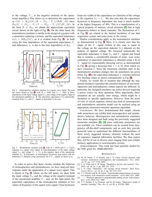
Fig. 2. Memcapacitor emulator response to a square wave signal. We used<br />
the circuit shown in Fig. 1b with R = 480Ω <strong>and</strong> C 1 = 10µF. a Timedependence<br />
of the input voltage signal V in <strong>and</strong> voltage at the negative input of<br />
the operational amplifier A 1 . b. The equivalent capacitance C(t) numerically<br />
extracted from V in <strong>and</strong> V − signals as described in the text.<br />
Voltage (V)<br />
3<br />
2<br />
1<br />
0<br />
-1<br />
-2<br />
-3<br />
-4<br />
V in<br />
;<br />
V -<br />
;<br />
a<br />
0.0 0.2 0.4 0.6 0.8 1.0<br />
Time (s)<br />
exp(-(t-0.17)∗11)<br />
exp(-(t-0.36)∗20)<br />
L (H)<br />
45<br />
40<br />
35<br />
30<br />
25<br />
20<br />
b<br />
-2 0 2<br />
V L<br />
(V)<br />
Fig. 3. Meminductor emulator (Fig. 1c with R = 480Ω <strong>and</strong> C 1 = 10µF)<br />
response to a square wave signal. a Time-dependence of the input voltage<br />
signal V in <strong>and</strong> voltage V − = V L at the negative input of the operational<br />
amplifier A 1 . b Schematics of meminductor hysteresis loop drawn with the<br />
inductance L obtained using exponential fits to V − signals as shown in a.<br />
In order to prove that these <strong>circuits</strong> emulate the behavior<br />
of <strong>memcapacitors</strong> <strong>and</strong> <strong>meminductors</strong>, we have analyzed their<br />
response under the application of a square wave signal. This<br />
is shown in Fig. 2, where, on the left panel, we show both<br />
the input voltage V in <strong>and</strong> the voltage at the negative terminal<br />
of the operational amplifier V − , <strong>and</strong>, on the right panel, the<br />
equivalent capacitance of the memcapacitor emulator at two<br />
values of frequency of the square wave signal. Clear hysteresis<br />
loops are visible in the capacitance as a function of the voltage<br />
at the capacitor V C = V − . We also note that the capacitance<br />
hysteresis is frequency dependent: the loop is much smaller<br />
at the higher frequency of 8Hz. This is a manifestation of a<br />
typical property of memory circuit elements [1] that at high<br />
frequencies behave as linear elements. The fluctuations of C<br />
in Fig. 2b are related to the limited resolution of our data<br />
acquisition system <strong>and</strong> some noise in the circuit.<br />
Similar considerations apply to the meminductor emulator<br />
as demonstrated in Fig. 3. Here, it is clearly seen that the<br />
shape of the V − signal (which in this case is equal to<br />
the voltage on the equivalent inductor V L ) depends on the<br />
polarity of applied voltage. We extracted numerically the<br />
equivalent inductance L from V in <strong>and</strong> V − signals <strong>and</strong> found<br />
that it contains a considerable amount of noise. Less noisy<br />
estimation of equivalent inductance is obtained using a fit of<br />
V − signal by exponentially decaying curves as demonstrated<br />
in Fig. 3a giving a decaying time τ = L/R, from which we<br />
have extracted L. Since the memristor emulator state in the<br />
meminductor emulator changes fast (its parameters are given<br />
below Eq. (1)), the equivalent inductance L switches between<br />
two limiting values as shown schematically in Fig. 3b.<br />
Finally, we would like to mention that although the suggested<br />
emulators reproduce the essential features of real <strong>memcapacitors</strong><br />
<strong>and</strong> <strong>meminductors</strong>, certain aspects are different. In<br />
particular, the designed emulators are active devices requiring<br />
a power source for their operation. More importantly, these<br />
emulators do not actually store energy, which might be a<br />
limitation in specific applications. However, from the point<br />
of view of circuit response, almost any kind of memcapacitor<br />
<strong>and</strong> meminductor operation model can be realized using an<br />
appropriate memristor-emulator operation algorithm.<br />
Conclusions: We have demonstrated that simple <strong>circuits</strong><br />
with memristors can exhibit both memcapacitive <strong>and</strong> meminductive<br />
behavior. Memcapacitor <strong>and</strong> meminductor emulators<br />
have been designed <strong>and</strong> built using the previously suggested<br />
memristor emulator [4], [5] since solid-state memristors are<br />
not available yet. These emulators can be created from inexpensive<br />
off-the-shelf components, <strong>and</strong> as such they provide<br />
powerful tools to underst<strong>and</strong> the different functionalities of<br />
these newly suggested memory elements without the need<br />
of expensive material fabrication facilities. We thus expect<br />
they will be of use in diverse areas ranging from non-volatile<br />
memory applications to neuromorphic <strong>circuits</strong>.<br />
Acknowledgment: This work has been partially funded by<br />
the NSF grant No. DMR-0802830.<br />
REFERENCES<br />
[1] M. Di Ventra, Y. V. Pershin, <strong>and</strong> L. O. Chua, “Circuit elements with<br />
memory: memristors, <strong>memcapacitors</strong> <strong>and</strong> <strong>meminductors</strong>,” Proc. IEEE,<br />
vol. 97, pp. 1717–1724, 2009.<br />
[2] L. O. Chua <strong>and</strong> S. M. Kang, “<strong>Memristive</strong> devices <strong>and</strong> systems,” Proc.<br />
IEEE, vol. 64, no. 2, pp. 209–223, 1976.<br />
[3] L. O. Chua, “Memristor - the missing circuit element,” IEEE Trans.<br />
Circuit Theory, vol. 18, no. 5, pp. 507–519, 1971.<br />
[4] Y. V. Pershin <strong>and</strong> M. Di Ventra, “Experimental demonstration of associative<br />
memory with memristive neural networks,” <strong>arXiv</strong>:0905.2935, 2009.<br />
[5] ——, “Practical approach to programmable analog <strong>circuits</strong> with memristors,”<br />
<strong>arXiv</strong>:0908.3162, 2009.<br />
[6] Y. V. Pershin, S. La Fontaine, <strong>and</strong> M. Di Ventra, “<strong>Memristive</strong> model of<br />
amoeba’s learning,” Phys. Rev. E, vol. 80, p. 021926, 2009.