Memristive circuits simulate memcapacitors and meminductors - arXiv
Memristive circuits simulate memcapacitors and meminductors - arXiv
Memristive circuits simulate memcapacitors and meminductors - arXiv

Create successful ePaper yourself
Turn your PDF publications into a flip-book with our unique Google optimized e-Paper software.
1<br />
<strong>Memristive</strong> <strong>circuits</strong> <strong>simulate</strong> <strong>memcapacitors</strong> <strong>and</strong><br />
<strong>meminductors</strong><br />
Yuriy V. Pershin <strong>and</strong> Massimiliano Di Ventra<br />
<strong>arXiv</strong>:0910.1583v2 [physics.ins-det] 18 Jan 2010<br />
Abstract—We suggest electronic <strong>circuits</strong> with memristors (resistors<br />
with memory) that operate as <strong>memcapacitors</strong> (capacitors<br />
with memory) <strong>and</strong> <strong>meminductors</strong> (inductors with memory).<br />
Using a memristor emulator, the suggested <strong>circuits</strong> have been<br />
built <strong>and</strong> their operation has been demonstrated, showing a useful<br />
<strong>and</strong> interesting connection between the three memory elements.<br />
Index Terms—Memory, Analog <strong>circuits</strong>, Analog memories.<br />
Introduction: Memcapacitive <strong>and</strong> meminductive systems are<br />
two recently postulated classes of circuit elements with memory<br />
[1] that complement the class of memristive systems [2],<br />
[3]. Their main characteristic is a hysteretic loop - which may<br />
or may not pass through the origin [1] - in their constitutive<br />
variables (charge-voltage for <strong>memcapacitors</strong> <strong>and</strong> current-flux<br />
for <strong>meminductors</strong>) when driven by a periodic input, <strong>and</strong>,<br />
unlike memristors, they can store energy. As of today, a few<br />
systems have been found to operate as <strong>memcapacitors</strong> <strong>and</strong><br />
<strong>meminductors</strong> (see [1] <strong>and</strong> references therein). However, these<br />
are neither available on the market yet, nor their properties<br />
can be easily tuned to investigate their role in more complex<br />
<strong>circuits</strong>. The same can be said about memristive systems.<br />
Therefore, electronic emulators of such memory elements that<br />
could be easily built <strong>and</strong> tuned would be highly desirable.<br />
We have previously designed <strong>and</strong> built a memristor emulator<br />
<strong>and</strong> shown its use in neuromorphic <strong>and</strong> programmable analog<br />
<strong>circuits</strong> [4], [5]. In this Letter, we use such memristor emulator<br />
to design <strong>and</strong> build memcapacitor <strong>and</strong> meminductor emulators,<br />
<strong>and</strong> prove experimentally their main properties. Since all of<br />
these emulators can be built from inexpensive off-the-shelf<br />
components we expect them to be extremely useful in the<br />
design, underst<strong>and</strong>ing <strong>and</strong> simulations of complex <strong>circuits</strong> with<br />
memory.<br />
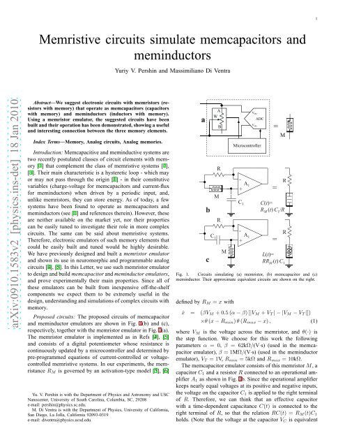
Proposed <strong>circuits</strong>: The proposed <strong>circuits</strong> of memcapacitor<br />
<strong>and</strong> meminductor emulators are shown in Fig. 1(b) <strong>and</strong> (c),<br />
respectively, together with the memristor emulator in Fig. 1(a).<br />
The memristor emulator is implemented as in Refs [4], [5]<br />
<strong>and</strong> consists of a digital potentiometer whose resistance is<br />
continuously updated by a microcontroller <strong>and</strong> determined by<br />
pre-programmed equations of current-controlled or voltagecontrolled<br />
memristive systems. In our experiments, the memristance<br />
R M is governed by an activation-type model [5], [6]<br />
Yu. V. Pershin is with the Department of Physics <strong>and</strong> Astronomy <strong>and</strong> USC<br />
Nanocenter, University of South Carolina, Columbia, SC, 29208<br />
e-mail: pershin@physics.sc.edu.<br />
M. Di Ventra is with the Department of Physics, University of California,<br />
San Diego, La Jolla, California 92093-0319<br />
e-mail: diventra@physics.ucsd.edu.<br />
V INa<br />
b<br />
c<br />
A<br />
W<br />
B<br />
R<br />
M<br />
R<br />
V IN+<br />
ADC<br />
Microcontroller<br />
=<br />
M<br />
- A<br />
R<br />
+<br />
A 1<br />
=<br />
C 1<br />
C(t)=<br />
R M (t) C 1 /R<br />
- C 1 A 1<br />
+ =<br />
M<br />
R<br />
L(t)=<br />
RR M (t) C 1<br />
Fig. 1. Circuits simulating (a) memristor, (b) memcapacitor <strong>and</strong> (c)<br />
meminductor. Their approximate equivalent <strong>circuits</strong> are shown on the right.<br />
defined by R M = x with<br />
ẋ = (βV M +0.5(α−β)[|V M +V T |−|V M −V T |])<br />
×θ(x−R min )θ(R max −x), (1)<br />
where V M is the voltage across the memristor, <strong>and</strong> θ(·) is<br />
the step function. We choose for this work the following<br />
parameters α = 0, β = 62kΩ/(V·s) (used in the memcapacitor<br />
emulator), β = 1MΩ/(V·s) (used in the meminductor<br />
emulator), V T = 1V, R min = 5kΩ <strong>and</strong> R max = 10kΩ.<br />
The memcapacitor emulator consists of this memristorM, a<br />
capacitor C 1 <strong>and</strong> a resistor R connected to an operational amplifier<br />
A 1 as shown in Fig. 1b. Since the operational amplifier<br />
keeps nearly equal voltages at its positive <strong>and</strong> negative inputs,<br />
the voltage on the capacitor C 1 is applied to the right terminal<br />
of R. Therefore, we can think that an effective capacitor<br />
with a time-dependent capacitance C(t) is connected to the<br />
right terminal of R, so that the relation RC(t) = R M (t)C 1<br />
holds. (Note that the voltage at the capacitor V C is equivalent
2<br />
to the voltage, V − , at the negative terminal of the operational<br />
amplifier.) This allows us to determine the capacitance<br />
as C(t) = R M (t)C 1 /R = (V in − V − )/(RdV − /dt) since<br />
R M (t) = (V in − V − )/I = (V in − V − )/(C 1 dV − /dt). In<br />
the limit R ≪ R M , we obtain the approximate equivalent<br />
circuit shown on the right of Fig. 1b. On the other h<strong>and</strong>, the<br />
meminductor emulator is similar to the design of a gyrator with<br />
a memristor replacing a resistor, <strong>and</strong> the equivalent inductance<br />
L(t) = RR M (t)C 1 , as it is evident from Fig. 1c. In both<br />
cases, the time dependence of the equivalent capacitance, C,<br />
<strong>and</strong> inductance, L, is due to the time dependence of R M .<br />
Voltage (V)<br />
2<br />
1<br />
0<br />
-1<br />
-2<br />
a<br />
V in<br />
V -<br />
ω=8Hz<br />
0.00 0.25 0.50<br />
Time (s)<br />
C (µF)<br />
300<br />
250<br />
200<br />
150<br />
100<br />
b<br />
ω=4Hz<br />
ω=8Hz<br />
-1 0 1<br />
V C<br />
(V)<br />
Fig. 2. Memcapacitor emulator response to a square wave signal. We used<br />
the circuit shown in Fig. 1b with R = 480Ω <strong>and</strong> C 1 = 10µF. a Timedependence<br />
of the input voltage signal V in <strong>and</strong> voltage at the negative input of<br />
the operational amplifier A 1 . b. The equivalent capacitance C(t) numerically<br />
extracted from V in <strong>and</strong> V − signals as described in the text.<br />
Voltage (V)<br />
3<br />
2<br />
1<br />
0<br />
-1<br />
-2<br />
-3<br />
-4<br />
V in<br />
;<br />
V -<br />
;<br />
a<br />
0.0 0.2 0.4 0.6 0.8 1.0<br />
Time (s)<br />
exp(-(t-0.17)∗11)<br />
exp(-(t-0.36)∗20)<br />
L (H)<br />
45<br />
40<br />
35<br />
30<br />
25<br />
20<br />
b<br />
-2 0 2<br />
V L<br />
(V)<br />
Fig. 3. Meminductor emulator (Fig. 1c with R = 480Ω <strong>and</strong> C 1 = 10µF)<br />
response to a square wave signal. a Time-dependence of the input voltage<br />
signal V in <strong>and</strong> voltage V − = V L at the negative input of the operational<br />
amplifier A 1 . b Schematics of meminductor hysteresis loop drawn with the<br />
inductance L obtained using exponential fits to V − signals as shown in a.<br />
In order to prove that these <strong>circuits</strong> emulate the behavior<br />
of <strong>memcapacitors</strong> <strong>and</strong> <strong>meminductors</strong>, we have analyzed their<br />
response under the application of a square wave signal. This<br />
is shown in Fig. 2, where, on the left panel, we show both<br />
the input voltage V in <strong>and</strong> the voltage at the negative terminal<br />
of the operational amplifier V − , <strong>and</strong>, on the right panel, the<br />
equivalent capacitance of the memcapacitor emulator at two<br />
values of frequency of the square wave signal. Clear hysteresis<br />
loops are visible in the capacitance as a function of the voltage<br />
at the capacitor V C = V − . We also note that the capacitance<br />
hysteresis is frequency dependent: the loop is much smaller<br />
at the higher frequency of 8Hz. This is a manifestation of a<br />
typical property of memory circuit elements [1] that at high<br />
frequencies behave as linear elements. The fluctuations of C<br />
in Fig. 2b are related to the limited resolution of our data<br />
acquisition system <strong>and</strong> some noise in the circuit.<br />
Similar considerations apply to the meminductor emulator<br />
as demonstrated in Fig. 3. Here, it is clearly seen that the<br />
shape of the V − signal (which in this case is equal to<br />
the voltage on the equivalent inductor V L ) depends on the<br />
polarity of applied voltage. We extracted numerically the<br />
equivalent inductance L from V in <strong>and</strong> V − signals <strong>and</strong> found<br />
that it contains a considerable amount of noise. Less noisy<br />
estimation of equivalent inductance is obtained using a fit of<br />
V − signal by exponentially decaying curves as demonstrated<br />
in Fig. 3a giving a decaying time τ = L/R, from which we<br />
have extracted L. Since the memristor emulator state in the<br />
meminductor emulator changes fast (its parameters are given<br />
below Eq. (1)), the equivalent inductance L switches between<br />
two limiting values as shown schematically in Fig. 3b.<br />
Finally, we would like to mention that although the suggested<br />
emulators reproduce the essential features of real <strong>memcapacitors</strong><br />
<strong>and</strong> <strong>meminductors</strong>, certain aspects are different. In<br />
particular, the designed emulators are active devices requiring<br />
a power source for their operation. More importantly, these<br />
emulators do not actually store energy, which might be a<br />
limitation in specific applications. However, from the point<br />
of view of circuit response, almost any kind of memcapacitor<br />
<strong>and</strong> meminductor operation model can be realized using an<br />
appropriate memristor-emulator operation algorithm.<br />
Conclusions: We have demonstrated that simple <strong>circuits</strong><br />
with memristors can exhibit both memcapacitive <strong>and</strong> meminductive<br />
behavior. Memcapacitor <strong>and</strong> meminductor emulators<br />
have been designed <strong>and</strong> built using the previously suggested<br />
memristor emulator [4], [5] since solid-state memristors are<br />
not available yet. These emulators can be created from inexpensive<br />
off-the-shelf components, <strong>and</strong> as such they provide<br />
powerful tools to underst<strong>and</strong> the different functionalities of<br />
these newly suggested memory elements without the need<br />
of expensive material fabrication facilities. We thus expect<br />
they will be of use in diverse areas ranging from non-volatile<br />
memory applications to neuromorphic <strong>circuits</strong>.<br />
Acknowledgment: This work has been partially funded by<br />
the NSF grant No. DMR-0802830.<br />
REFERENCES<br />
[1] M. Di Ventra, Y. V. Pershin, <strong>and</strong> L. O. Chua, “Circuit elements with<br />
memory: memristors, <strong>memcapacitors</strong> <strong>and</strong> <strong>meminductors</strong>,” Proc. IEEE,<br />
vol. 97, pp. 1717–1724, 2009.<br />
[2] L. O. Chua <strong>and</strong> S. M. Kang, “<strong>Memristive</strong> devices <strong>and</strong> systems,” Proc.<br />
IEEE, vol. 64, no. 2, pp. 209–223, 1976.<br />
[3] L. O. Chua, “Memristor - the missing circuit element,” IEEE Trans.<br />
Circuit Theory, vol. 18, no. 5, pp. 507–519, 1971.<br />
[4] Y. V. Pershin <strong>and</strong> M. Di Ventra, “Experimental demonstration of associative<br />
memory with memristive neural networks,” <strong>arXiv</strong>:0905.2935, 2009.<br />
[5] ——, “Practical approach to programmable analog <strong>circuits</strong> with memristors,”<br />
<strong>arXiv</strong>:0908.3162, 2009.<br />
[6] Y. V. Pershin, S. La Fontaine, <strong>and</strong> M. Di Ventra, “<strong>Memristive</strong> model of<br />
amoeba’s learning,” Phys. Rev. E, vol. 80, p. 021926, 2009.