You also want an ePaper? Increase the reach of your titles
YUMPU automatically turns print PDFs into web optimized ePapers that Google loves.
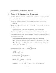
Physics 116B<br />
<strong>TLC555</strong> <strong>Timer</strong><br />
Circuit<br />
Physics116B, 1/17/07<br />
D. Pellett<br />
1
<strong>TLC555</strong> <strong>Timer</strong> Circuit<br />
• Variation on widely-used 555 timer using MOSFETs rather<br />
than BJTs<br />
• Can be used to make (among other things):<br />
• Schmitt trigger<br />
• astable multivibrator (relaxation oscillator)<br />
• monostable multivibrator (“one-shot” circuit) – a simple<br />
timer based on an RC network<br />
• The basic circuit operation can be described without delving<br />
fully into its internal logic<br />
2
<strong>TLC555</strong> Functional Description<br />
Functional Block Diagram<br />
VDD<br />
Function Table<br />
Assumes Control input not connected<br />
Reset Trigger Threshold Output Discharge<br />
2 VDD/3<br />
VDD/3<br />
Latch<br />
Inverter<br />
(circles indicate<br />
logic negation)<br />
Low<br />
High<br />
Don’t<br />
Care<br />
< VDD/3<br />
Don’t<br />
Care<br />
Don’t<br />
Care<br />
Low<br />
High<br />
Grounded<br />
Floating<br />
High > VDD/3 >2 VDD/3 Low Grounded<br />
Comparators<br />
(circle is “-” input)<br />
n-channel<br />
enhancement-mode<br />
MOSFET<br />
High > VDD/3 < 2 VDD/3<br />
Based on figure from <strong>TLC555</strong> data sheet © Radio Shack<br />
As previously<br />
established<br />
• We will set VDD = 5 V so logic levels will be 0 V (Low) and 5 V (High)<br />
• Connect Reset to ground, leave Control unconnected<br />
• Circuit performance described by shaded area in Function Table<br />
• Threshold and Trigger are analog inputs in range 0 to 5 V<br />
• Output is a logic level: 0 V or 5 V<br />
• Discharge is connected to an n-channel MOSFET drain whose source is grounded.<br />
• Discharge is grounded only when Output is Low. Otherwise, it is an open circuit<br />
(“floating”).<br />
3
<strong>TLC555</strong> as Schmitt Trigger<br />
Functional Block Diagram<br />
VDD<br />
Function Table<br />
Assumes Control input not connected<br />
Reset Trigger Threshold Output Discharge<br />
VIN<br />
2 VDD/3<br />
VDD/3<br />
Latch<br />
VOUT<br />
Inverter<br />
(circles indicate<br />
logic negation)<br />
Low<br />
High<br />
Don’t<br />
Care<br />
< VDD/3<br />
Don’t<br />
Care<br />
Don’t<br />
Care<br />
Low<br />
High<br />
Grounded<br />
Floating<br />
High > VDD/3 >2 VDD/3 Low Grounded<br />
Comparators<br />
(circle is “-” input)<br />
n-channel<br />
enhancement-mode<br />
MOSFET<br />
High > VDD/3 < 2 VDD/3<br />
Based on figure from <strong>TLC555</strong> data sheet © Radio Shack<br />
• Connect Threshold and Trigger together to form a single input VIN. We get an<br />
inverting Schmitt trigger with VD = 2 VDD/3 and VU = VDD/3<br />
• You can see this from the table.<br />
• Start with VIN = 0 V. Since Trigger < VDD/3, Output is High (VOUT = 5 V)<br />
• Now increase VIN. Output does not go low until VIN crosses VD = 2VDD/3<br />
• Output remains “as previously established” (High) for VDD/3 < VIN < 2VDD/3<br />
• It remains low as VIN increases to 5 V.<br />
• Now decrease VIN toward 0. VOUT does not go high until VIN falls below VU = VDD/3.<br />
As previously<br />
established<br />
VOUT<br />
5 V<br />
0<br />
0 VU V D<br />
Schmitt trigger<br />
response curve<br />
5 V<br />
VIN<br />
4
<strong>TLC555</strong> as Relaxation Oscillator<br />
VDD<br />
Function Table<br />
Assumes Control input not connected<br />
R<br />
‘<br />
Reset Trigger Threshold Output Discharge<br />
VIN<br />
2 VDD/3<br />
VDD/3<br />
‘<br />
Latch<br />
VOUT<br />
Inverter<br />
(circles indicate<br />
logic negation)<br />
Low<br />
High<br />
Don’t<br />
Care<br />
< VDD/3<br />
Don’t<br />
Care<br />
Don’t<br />
Care<br />
Low<br />
High<br />
Grounded<br />
Floating<br />
C<br />
‘<br />
Comparators<br />
(circle is “-” input)<br />
n-channel<br />
enhancement-mode<br />
MOSFET<br />
High > VDD/3 >2 VDD/3 Low Grounded<br />
High > VDD/3 < 2 VDD/3<br />
Based on figure from <strong>TLC555</strong> data sheet © Radio Shack<br />
• Again, connect Threshold and Trigger together to form a single input VIN and<br />
get an inverting Schmitt trigger with VD = 2 VDD/3 and VU = VDD/3.<br />
• Connect a capacitor C between VIN and ground and a resistor R between<br />
VIN and VOUT.<br />
• Just as we showed in class, we have converted an inverting Schmitt trigger<br />
into a relaxation oscillator.<br />
• If the output is High, C charges toward 5 V until VIN reaches VD, at which<br />
point the output goes Low. Then C discharges toward 0 V until VIN<br />
reaches VU and the output goes High. The process continues.<br />
As previously<br />
established<br />
VOUT<br />
5 V<br />
0<br />
0 VU V D<br />
Schmitt trigger<br />
response curve<br />
5 V<br />
VIN<br />
5
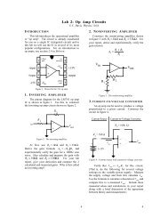
Observe the pulse on the trigger input of the timer and sketch it to include in your report. Observe the<br />
operation of the timer circuit for timing resistances of 100 kΩ and 1.0 MΩ. Measure the periods. Analyze<br />
the operation of the circuit and compare the measured periods from what you expect from the analysis.<br />
Relaxation Oscillator Circuit<br />
<strong>TLC555</strong> Pinout<br />
• Note Reset is connected to VDD (“active low” input)<br />
Figure 1: Relaxation oscillator diagram with thermistor resistance chart.<br />
• The Control input is bypassed to ground with a .01 μF capacitor to<br />
prevent pickup of interfering signals (glitches)<br />
• It is also a good idea to put a .01 μF capacitor between VDD and ground<br />
at the chip to filter out glitches on the power supply connection<br />
6
<strong>TLC555</strong> as “One-Shot” Pulse Generator<br />
R<br />
VDD VDD<br />
‘<br />
Function Table<br />
Assumes Control input not connected<br />
Reset Trigger Threshold Output Discharge<br />
VC<br />
VIN = 5V<br />
C<br />
2 VDD/3<br />
VDD/3<br />
‘<br />
‘<br />
Latch<br />
Comparators<br />
(circle is “-” input)<br />
VOUT<br />
Inverter<br />
(circles indicate<br />
logic negation)<br />
Low<br />
High<br />
Don’t<br />
Care<br />
< VDD/3<br />
Don’t<br />
Care<br />
Don’t<br />
Care<br />
Low<br />
High<br />
Grounded<br />
Floating<br />
High > VDD/3 >2 VDD/3 Low Grounded<br />
High > VDD/3 < 2 VDD/3<br />
As previously<br />
established<br />
Based on figure from <strong>TLC555</strong> data sheet © Radio Shack<br />
• We do some rewiring of the relaxation oscillator to get a One-Shot (monostable<br />
multivibrator). Trigger has been disconnected from Threshold and R connects to VDD (5 V)<br />
instead of Output.<br />
• Threshold is connected to Discharge, which shorts the capacitor and forces VC = 0<br />
when Output is low (see table).<br />
• Now Trigger serves as the input VIN, normally set High (5 V).<br />
• If VIN remains high and the output is high, C will charge through R toward VDD (5 V) until<br />
Threshold reaches 2VDD/3. Then Output goes low, Discharge and Threshold are grounded, and<br />
VC = 0 V. This is the stable state (VIN high, VOUT low).<br />
7
<strong>TLC555</strong> as “One-Shot” Pulse Generator<br />
R<br />
VDD VDD<br />
‘<br />
Function Table<br />
Assumes Control input not connected<br />
Reset Trigger Threshold Output Discharge<br />
VC<br />
VIN = 5V<br />
C<br />
2 VDD/3<br />
VDD/3<br />
‘<br />
‘<br />
Latch<br />
Comparators<br />
(circle is “-” input)<br />
VOUT<br />
Inverter<br />
(circles indicate<br />
logic negation)<br />
Low<br />
High<br />
Don’t<br />
Care<br />
< VDD/3<br />
Don’t<br />
Care<br />
Don’t<br />
Care<br />
Low<br />
High<br />
Grounded<br />
Floating<br />
High > VDD/3 >2 VDD/3 Low Grounded<br />
High > VDD/3 < 2 VDD/3<br />
As previously<br />
established<br />
Based on figure from <strong>TLC555</strong> data sheet © Radio Shack<br />
• Start in the stable state: VIN high, VOUT low, Discharge and Threshold<br />
grounded, and VC = 0 V.<br />
• A short pulse on the input causing VIN to fall below VDD/3 will set<br />
Output high, ungrounding Discharge and allowing C to charge<br />
through R toward 5 V. The output remains high while C is<br />
charging.<br />
• When VC (Threshold input) reaches 2VDD/3, Output goes low<br />
again, shorting C to ground, terminating the output pulse and<br />
returning the one-shot its the stable state. The result is an output<br />
pulse whose width T is related to the RC time constant.<br />
8
One-Shot Circuit for Lab<br />
Figure 1: Relaxation oscillator diagram with thermistor resistance chart.<br />
<strong>TLC555</strong> Pinout<br />
10 μs positive<br />
input pulse<br />
(TTL level)<br />
Pulse inverter<br />
and stretcher<br />
• Suppose In is held at 0 V for a long time. Since the BJT is cut off, the 555 Trigger<br />
input is pulled high by R′ (charging FigureC′ 2: One-shot so Trigger (timer) →5 circuit. V). Now the one-shot is in its<br />
stable state with Output low.<br />
• A short positive input pulse forces the BJT 2into saturation (like a closed switch)<br />
discharging C′. This pulls the Trigger input low momentarily and starts the <strong>TLC555</strong><br />
output pulse. The R′C′ time constant is long enough to assure that the <strong>TLC555</strong> is<br />
triggered (input circuit acts as pulse “stretcher” as well as an inverter).<br />
• The width of the one-shot output pulse T equals the time required for the<br />
voltage VC across the timing capacitor C to go from 0 V to 2/3 VDD.<br />
VC<br />
One-shot<br />
circuit<br />
T<br />
Output pulse of<br />
width T<br />
9