Lab 8: Differential Amplifier - Department of Physics - UC Davis
Lab 8: Differential Amplifier - Department of Physics - UC Davis
Lab 8: Differential Amplifier - Department of Physics - UC Davis

You also want an ePaper? Increase the reach of your titles
YUMPU automatically turns print PDFs into web optimized ePapers that Google loves.
This reduces to<br />
I 1 = I 2 + V 1 /R E .<br />
I 1 is now greater than I 2 ,soI 2 must have decreased since the total, I ′ , is approximately<br />
constant. Reducing I 2 lowers the voltage drop across R C ,soV out increases. V 1 is the noninverting<br />
input.<br />
In the same way, raising V 2 slightly with V 1 grounded increases I 2 . This now increases<br />
the voltage drop across R C and lowers V out . V 2 is the inverting input.<br />
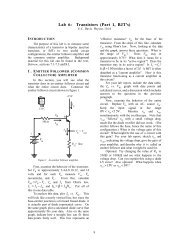
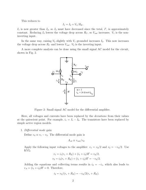
A more complete analysis can be done using the small signal AC model for the circuit,<br />
shown in Fig. 2.<br />
R C<br />
v out<br />
v 1<br />
r e r e<br />
v 2<br />
i R 1 E R E<br />
v<br />
i 2 A<br />
αi 1 αi2<br />
α ≈ 1<br />
i'<br />
R'<br />
r e ≈ 26 Ω mA/I EQ<br />
Figure 2: Small signal AC model for the differential amplifier.<br />
Here, all voltages and currents have been replaced by the deviations from their values<br />
at the quiescient point. For example, i 1 = I 1 − I 0 . The transistors have been replaced by<br />
simple active region models.<br />
1. <strong>Differential</strong> mode gain:<br />
Define v d ≡ v 1 − v 2 . The differential mode gain is<br />
A vd ≡ v out /v d .<br />
Apply the following input voltages to the amplifier: v 1 = v d /2andv 2 = −v d /2. Use<br />
KVL:<br />
v 1 = i 1 (r e + R E )+(i 1 + i 2 )R ′ = v d /2,<br />
v 2 = i 2 (r e + R E )+(i 1 + i 2 )R ′ = −v d /2.<br />
Adding the equations and collecting terms results in i 2 = −i 1 , which also leads to<br />
v A =(i 1 + i 2 )R ′ =0. Therefore,<br />
i 2 = v 2 /(r e + R E )=−v d /2(r e + R E ).<br />
2