PIXUS 80i i80 - Piezas y Partes
PIXUS 80i i80 - Piezas y Partes
PIXUS 80i i80 - Piezas y Partes

You also want an ePaper? Increase the reach of your titles
YUMPU automatically turns print PDFs into web optimized ePapers that Google loves.
<strong>PIXUS</strong> <strong>80i</strong><br />
<strong>i80</strong><br />
REVISION 0<br />
8582A001AA<br />
8582A002AA<br />
8582A003AA<br />
8582A005AA<br />
8582A008AA<br />
8582A009AA<br />
8582A010AA<br />
8582A011AA<br />
8582A012AA<br />
8582A013AA<br />
8582A014AA<br />
8582A015AA<br />
8582A016AA<br />
120V(US)<br />
120V(CA)<br />
120V(LAM)<br />
220V-240V(EUR)<br />
220V-240V(ASA)<br />
220V-240V(AU)<br />
220V-240V(KR)<br />
220V-240V(GB)<br />
100V(JPN)<br />
120V(TW)<br />
220V-240V(HK)<br />
220V-240V(CN)<br />
220V-240V(EUM)<br />
JAN. 2004<br />
QY8-31BZ-000<br />
COPYRIGHT © 2004 CANON INC. CANON <strong>i80</strong>/<strong>PIXUS</strong> <strong>80i</strong> 0104 N 0.00-0
0104 N 0.00-0
<strong>PIXUS</strong> <strong>80i</strong><br />
<strong>i80</strong>
Application<br />
This manual has been issued by Canon Inc. for qualified<br />
person to learn technical theory, installation, maintenance,<br />
and repair of products. This manual covers all localities<br />
where the products are sold. For this reason, there may be<br />
information in this manual that does not apply to your<br />
locality.<br />
Corrections<br />
This manual could include technical inaccuracies or<br />
typographical errors due to improvements or changes in the<br />
products. When changes occur in applicable products or in<br />
the content of this manual, Canon will release technical<br />
information as the need arises. In the event of major<br />
changes in the contents of this manual over a long or short<br />
period. Canon will issue a new editions of this manual.<br />
The following paragraph does not apply to any countries<br />
where such provisions are inconsistent with local low.<br />
Trademarks<br />
The product names and company names described in this<br />
manual are the registered trademarks of the individual<br />
companies.<br />
Copyright<br />
This manual is copyrighted with all rights reserved. Under<br />
the copyright laws, this manual may not be copied,<br />
reproduced or translated into another language, in whole or<br />
in part, without the written consent of Canon Inc.<br />
Copyright © 2004 by Canon Inc.<br />
CANON INC.<br />
Inkjet SFP Quality Assurance Div.<br />
16-1, Shimonoge 3-chome, Takatsu-ku, Kawasaki-shi,<br />
Kanagawa 213-8512, Japan<br />
DTP System<br />
This manual was produced on an Apple ® Power Macintosh ®<br />
G3 personal computer and Canon LBP-2030PS laser beam<br />
printer, final pages were printed on Valityper ® 4300J.<br />
Parts layout pictures were taken using Canon Digital Camera<br />
EOS D30, and edited with Adobe ® Photoshop ® 5.0.<br />
KEY No. and Logotypes were created using<br />
MACROMEDIA ® FreeHand ® 8J.<br />
Documents and page layouts were created using<br />
QuarkXpress ® 3.3J.<br />
Parts lists were created using Helix Tecnologies ® Herix<br />
Xpress ® and converted to EPS files.
I. CONTENTS<br />
A. ILLUSTRATION INDEX<br />
B. PARTS LAYOUT & PARTS LIST<br />
C. OPTIONS & CONSUMABLES<br />
D. SCREWS & WASHERS LIST<br />
E. TOOL<br />
F. NUMERICAL INDEX<br />
I
II.<br />
ABOUT THIS MANUAL<br />
A. ILLUSTRATION INDEX<br />
For illustration index, the parts layout<br />
illustrations in this parts catalog are<br />
listed in abbreviated form in order of<br />
illustration number to identify the pages<br />
they appear on. To find an illustration of<br />
a part, see the ILLUSTRATION INDEX.<br />
B. PARTS LAYOUT & PARTS LIST<br />
Parts layout illustration<br />
a) Parts search<br />
Find a part from the parts layout<br />
illustration and find its key number<br />
from the parts list to identify the part<br />
number and name. For screws, nuts,<br />
washers, lock washers, pins, spacers,<br />
see SCREWS &WASHERS LIST.<br />
Note: If parts have the same or similar<br />
shape but different specifications,<br />
their key number is assigned to<br />
several part numbers and names<br />
in the parts list.<br />
b) Parts replacement procedure<br />
To replace parts, the parts layout<br />
illustrations have figure numbers<br />
according to the disassembly procedure<br />
of the product. The parts that require<br />
careful work are shown the illustration.<br />
Parts list<br />
a) FIGURE & KEY No.<br />
The FIGURE & KEY No. column<br />
corresponds to the key numbers<br />
assigned to the parts in the parts<br />
layout illustration.<br />
It also corresponds to the part locations<br />
printed on the PC board.<br />
b) PART NUMBER<br />
The PART NUMBER column gives the<br />
part numbers corresponding to the key<br />
numbers. To order a part, indicate the<br />
part number clearly.<br />
Note: Parts marked NPN are not<br />
service parts.<br />
c) RANK<br />
The service parts with N in the RANK<br />
column are order parts.<br />
d) QTY<br />
The QTY column gives the number of<br />
parts in the corresponding components<br />
layout illustration.<br />
e) DESCRIPTION<br />
The DESCRIPTION column gives the<br />
part names in English.<br />
To order a part, indicate the part<br />
name, too.<br />
C. OPTIONS & CONSUMABLES<br />
These are illustrations and a list of units<br />
that can be used as optional consumable<br />
equipments.<br />
D. SCREWS & WASHERS LIST<br />
This is a list of screws, nuts, washers,<br />
lock washers, pins, and spacers.<br />
The QTY column does not give the<br />
number of parts used.<br />
E. TOOL LIST<br />
This is a list of tools used for servicing<br />
products.<br />
F. NUMERICAL INDEX<br />
All the parts listed in this parts catalog<br />
are arranged in order of part number.<br />
You can identify part locations and<br />
names from the NUMERICAL INDEX.<br />
II
This page intentionally left blank<br />
III
FIGURE 1 PRINTER & PRINT HEAD<br />
See Page<br />
B - 1<br />
FIGURE 2<br />
OUTPUT COVER UNIT &<br />
I/F COVER<br />
See Page<br />
B - 3<br />
3<br />
2<br />
1<br />
1<br />
4<br />
FIGURE 3<br />
MAIN CASE UNIT<br />
See Page<br />
B - 5<br />
FIGURE 4<br />
PRESSING PLATE UNIT<br />
See Page<br />
B - 7<br />
Remove the claws in<br />
the alphabetical order.<br />
f<br />
h<br />
g<br />
b<br />
a<br />
e<br />
c<br />
d<br />
b<br />
c<br />
a<br />
d<br />
3<br />
g<br />
f<br />
h<br />
e<br />
4<br />
3<br />
2<br />
S1<br />
5<br />
S1<br />
2<br />
S3<br />
1<br />
A. ILLUSTRATION INDEX A-1<br />
S1<br />
1<br />
TAPE<br />
S1<br />
SCREW<br />
Remove the tape, and then<br />
remove the screw.<br />
Secure the cables with tape.<br />
S1<br />
S1<br />
S1<br />
S2<br />
6<br />
4
FIGURE 5<br />
FERRITE CORE<br />
(FFC & HARNESS)<br />
See Page<br />
B - 9<br />
FIGURE 6<br />
PRINT UNIT &<br />
DRAIN PACK ASS'Y<br />
See Page<br />
B - 11<br />
Insert the flexible cable<br />
into Key No. 1.<br />
Layout of Key No. 7 (in black lines) and<br />
3 (in pink).<br />
S3<br />
<br />
connector<br />
Key No. 3<br />
Key No. 7<br />
6<br />
7<br />
8<br />
5<br />
2 1<br />
Layout of Key No. 1, 2, and 3.<br />
4<br />
Insert the cables into<br />
Key No. 2, and wind it.<br />
3<br />
2<br />
1<br />
FIGURE 7<br />
BOARD PARTS<br />
See Page<br />
B - 13<br />
FIGURE 8<br />
INK ABSORBERS<br />
See Page<br />
B - 15<br />
S5<br />
1<br />
1<br />
S1<br />
S3<br />
3<br />
4<br />
2<br />
3<br />
2<br />
S3<br />
A-2
FIGURE 9<br />
CARRIAGE UNIT &<br />
PURGE UNIT<br />
See Page<br />
B - 17<br />
FIGURE 10<br />
MAIN BOARD PARTS &<br />
COIN BATTERY UNIT<br />
See Page<br />
B - 19<br />
NOTE 1 : At the first step, lower the head cap.<br />
2 : Raise the head cap, and then remove Key No. 22.<br />
3 : For Key No. 10 and 20, use a new one upon the re-installation.<br />
16<br />
17<br />
14<br />
7<br />
Raise the leading edge of the<br />
sensor arm upon the<br />
disinstallation of Key No. 14 and<br />
re-installation of Key No.17.<br />
S1<br />
S5<br />
4<br />
1<br />
S5<br />
3<br />
11 12<br />
S1<br />
8<br />
6<br />
9<br />
20<br />
10<br />
13<br />
S5<br />
15<br />
19<br />
S7<br />
5<br />
21<br />
S1<br />
18<br />
S5<br />
S7<br />
Layout of Key No. 5.<br />
S4<br />
2<br />
5<br />
S5<br />
6<br />
1<br />
4<br />
S1<br />
2<br />
S5<br />
22<br />
7<br />
Confirm the sensor arm<br />
and spring do not come off.<br />
3<br />
S6<br />
Remove three screws, and then<br />
remove Key No. 18.<br />
FIGURE 11<br />
OPTION& CONSUMABLES<br />
See Page<br />
C - 1<br />
FIGURE 12<br />
TOOL<br />
See Page<br />
E - 1<br />
5<br />
1<br />
T1<br />
T4<br />
2<br />
6<br />
3<br />
7<br />
FLOIL<br />
4<br />
T2<br />
8<br />
9<br />
T3<br />
T5<br />
10<br />
GREASE,<br />
EU-1<br />
QY9-0037-000<br />
100ml<br />
A-3
This page intentionally left blank<br />
A-4
B.<br />
PARTS LAYOUT & PARTS LIST<br />
FIGURE 1<br />
PRINTER & PRINT HEAD<br />
1<br />
B-1
FIGURE<br />
&<br />
KEY NO.<br />
PART NUMBER<br />
1 - 1 QY6-0052-000 1 PRINT HEAD<br />
R<br />
A<br />
N<br />
K<br />
Q<br />
T<br />
Y<br />
DESCRIPTION<br />
REMARKS<br />
B-2
FIGURE 2<br />
OUTPUT COVER UNIT & I/F COVER<br />
3<br />
2<br />
1<br />
4<br />
B-3
FIGURE<br />
&<br />
KEY NO.<br />
PART NUMBER<br />
R<br />
A<br />
N<br />
K<br />
Q<br />
T<br />
Y<br />
DESCRIPTION<br />
REMARKS<br />
2 - 1 QC1-4017-000 1 COVER, BT SLOT<br />
2 QC1-1099-000 1 COVER, SIDE R<br />
3 QC1-1098-000 1 COVER, SIDE L<br />
4 QM2-0289-000 1 OUTPUT SLOT COVER UNIT<br />
B-4
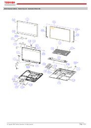
FIGURE 3<br />
MAIN CASE UNIT<br />
Remove the claws in<br />
the alphabetical order.<br />
f<br />
h<br />
g<br />
b<br />
a<br />
e<br />
c<br />
d<br />
b<br />
c<br />
a<br />
d<br />
3<br />
g<br />
f<br />
h<br />
e<br />
4<br />
S1<br />
5<br />
2<br />
S1<br />
1<br />
S1<br />
S2<br />
6<br />
B-5
FIGURE<br />
&<br />
KEY NO.<br />
PART NUMBER<br />
R<br />
A<br />
N<br />
K<br />
Q<br />
T<br />
Y<br />
DESCRIPTION<br />
REMARKS<br />
3 - 1 QC1-3997-000 1 PLATE, NAME R<br />
2 QC1-3996-000 1 PLATE, NAME L<br />
3 QM2-1110-000 1 MAIN CASE UNIT FOR <strong>i80</strong><br />
QM2-1120-000 1 MAIN CASE UNIT FOR <strong>PIXUS</strong> <strong>80i</strong><br />
4 QL2-0567-000 1 TRAY, FEED<br />
5 QC1-4002-000 1 COVER, PRINT HEAD FOR <strong>PIXUS</strong> <strong>80i</strong><br />
QC1-4003-000 1 COVER, PRINT HEAD FOR <strong>i80</strong><br />
6 NPN 1 PLATE, FRONT CRAMP R<br />
B-6
FIGURE 4<br />
PRESSING PLATE UNIT<br />
3<br />
2<br />
S3<br />
1<br />
S1<br />
TAPE<br />
SCREW<br />
Remove the tape, and then<br />
remove the screw.<br />
Secure the cables with tape.<br />
S1<br />
S1<br />
S1<br />
4<br />
B-7
FIGURE<br />
&<br />
KEY NO.<br />
PART NUMBER<br />
R<br />
A<br />
N<br />
K<br />
Q<br />
T<br />
Y<br />
DESCRIPTION<br />
REMARKS<br />
4 - 1 NPN 1 PLATE, CRAMP L<br />
2 NPN 1 PLATE, CRAMP R<br />
3 QM2-1115-000 1 PRESSING PLATE UNIT<br />
4 NPN 1 PLATE, SHIELD<br />
B-8
FIGURE 5<br />
FERRITE CORE (FFC & HARNESS)<br />
Insert the flexible cable<br />
into Key No. 1.<br />
S3<br />
2 1<br />
Insert the cables into<br />
Key No. 2, and wind it.<br />
B-9
FIGURE<br />
&<br />
KEY NO.<br />
PART NUMBER<br />
R<br />
A<br />
N<br />
K<br />
Q<br />
T<br />
Y<br />
DESCRIPTION<br />
REMARKS<br />
5 - 1 WE8-6074-000 1 CORE, FERRITE<br />
2 WE8-6045-000 1 CORE, FERRITE RING<br />
B-10
FIGURE 6<br />
PRINT UNIT & DRAIN PACK ASS'Y<br />
Layout of Key No. 7 (in black lines) and<br />
3 (in pink).<br />
<br />
connector<br />
Key No. 7<br />
Key No. 3<br />
6<br />
7<br />
8<br />
5<br />
Layout of Key No. 1, 2, and 3.<br />
4<br />
3<br />
2<br />
1<br />
B-11
FIGURE<br />
&<br />
KEY NO.<br />
PART NUMBER<br />
R<br />
A<br />
N<br />
K<br />
Q<br />
T<br />
Y<br />
DESCRIPTION<br />
REMARKS<br />
6 - 1 QK1-0053-000 1 CABLE, PG SENSOR FLEXIBLE<br />
2 QK1-0052-000 1 CABLE, IRDA FLEXIBLE<br />
3 QK1-0051-000 1 CABLE, PANEL FLEXIBLE<br />
4 QC1-1310-000 1 HOLDER, FLEXIBLE CABLE<br />
5 QC1-3998-000 1 FILM, TIMING SLIT STRIP<br />
6 QL2-0194-000 1 DRAIN PACK ASS'Y<br />
7 NPN 1 SHEET, EDGE COVER<br />
8 QM2-1111-000 1 PRINT UNIT<br />
B-12
FIGURE 7<br />
BOARD PARTS<br />
S5<br />
1<br />
S1<br />
S3<br />
3<br />
4<br />
2<br />
S3<br />
B-13
FIGURE<br />
&<br />
KEY NO.<br />
PART NUMBER<br />
R<br />
A<br />
N<br />
K<br />
Q<br />
T<br />
Y<br />
DESCRIPTION<br />
REMARKS<br />
7 - 1 QM2-1264-000 1 PANEL BOARD ASS'Y<br />
2 QM2-1266-000 1 DCD BOARD ASS'Y<br />
3 QM2-1119-000 1 USB BOARD ASS'Y<br />
4 QM2-0240-000 1 DOOR SENSOR BOARD ASS'Y<br />
B-14
FIGURE 8<br />
INK ABSORBERS<br />
1<br />
3<br />
2<br />
B-15
FIGURE<br />
&<br />
KEY NO.<br />
PART NUMBER<br />
R<br />
A<br />
N<br />
K<br />
Q<br />
T<br />
Y<br />
DESCRIPTION<br />
REMARKS<br />
8 - 1 QC1-1210-000 1 ABSORBER, INK<br />
2 QC1-1212-000 1 ABSORBER, INK WITH FILM<br />
3 QC1-1211-000 1 ABSORBER, INK<br />
B-16
FIGURE 9<br />
CARRIAGE UNIT & PURGE UNIT<br />
NOTE 1 : At the first step, lower the head cap.<br />
2 : Raise the head cap, and then remove Key No. 22.<br />
3 : For Key No. 10 and 20, use a new one upon the re-installation.<br />
16<br />
17<br />
Raise the leading edge of the<br />
sensor arm upon the<br />
disinstallation of Key No. 14 and<br />
re-installation of Key No.17.<br />
14<br />
7<br />
S1<br />
11 12<br />
S1<br />
8<br />
6<br />
9<br />
10<br />
S5<br />
15<br />
19<br />
S7<br />
5<br />
S1<br />
18<br />
S5<br />
S7<br />
20<br />
13<br />
21<br />
1<br />
4<br />
S1<br />
2<br />
S5<br />
22<br />
3<br />
S6<br />
Confirm the sensor arm<br />
and spring do not come off.<br />
Remove three screws, and then<br />
remove Key No. 18.<br />
B-17
FIGURE<br />
&<br />
KEY NO.<br />
PART NUMBER<br />
R<br />
A<br />
N<br />
K<br />
Q<br />
T<br />
Y<br />
DESCRIPTION<br />
REMARKS<br />
9 - 10 QC1-1163-000 1 SLIT RING, PAPER FEED ROLLER<br />
16 QC1-1205-000 1 BELT, CARRIAGE<br />
17 QM2-1116-000 1 CARRIAGE UNIT<br />
20 QA4-1021-000 1 SLIT RING, EJECT ROLLER<br />
22 QM2-0304-000 1 PURGE UNIT<br />
B-18
FIGURE 10<br />
MAIN BOARD PARTS & COIN BATTERY UNIT<br />
S5<br />
1<br />
S5<br />
3<br />
4<br />
2<br />
S4<br />
5<br />
S5<br />
6<br />
Layout of Key No. 5.<br />
7<br />
B-19
FIGURE<br />
&<br />
KEY NO.<br />
PART NUMBER<br />
R<br />
A<br />
N<br />
K<br />
Q<br />
T<br />
Y<br />
DESCRIPTION<br />
REMARKS<br />
10 - 1 QM2-1263-000 1 DCDC HARNESS ASS'Y<br />
2 QM2-0292-000 1 COIN BATTERY UNIT<br />
3 QM2-1258-000 1 DCDC BOARD ASS'Y<br />
4 QM2-1257-000 1 LOGIC BOARD ASS'Y<br />
5 QM2-1109-000 1 BLUETOOTH ASS'Y<br />
6 NPN 1 PLATE, FRONT CRAMP L<br />
7 QL2-0193-000 1 BASE ASS'Y<br />
B-20
C.<br />
OPTIONS & CONSUMABLES<br />
FIGURE 11<br />
OPTION & CONSUMABLES<br />
5<br />
1<br />
2<br />
6<br />
3<br />
7<br />
4<br />
8<br />
9<br />
10<br />
C-1
FIGURE<br />
&<br />
KEY NO.<br />
PART NUMBER<br />
R<br />
A<br />
N<br />
K<br />
Q<br />
T<br />
Y<br />
DESCRIPTION<br />
REMARKS<br />
11 - 1 NPN 1 BLACK INK TANK BCI-15BLACK CONSUMABLES<br />
2 NPN 1 COLOR INK TANK BCI-15COLOR CONSUMABLES<br />
3 QY5-0137-000 1 BLUETOOTH MODULE KIT JP<br />
QY5-0138-000 1 BLUETOOTH MODULE KIT US, CA<br />
QY5-0139-000 1 BLUETOOTH MODULE KIT ASA<br />
QY5-0140-000 1 BLUETOOTH MODULE KIT CN<br />
QY5-0141-000 1 BLUETOOTH MODULE KIT EUR<br />
QY5-0142-000 1 BLUETOOTH MODULE KIT TW<br />
4 QC1-4020-000 1 BAR, LOCK<br />
5 QK1-0005-000 1 CHARGE, BATTERY (W/O BATTERY)<br />
6 QK1-0006-000 1 BATTERY <strong>i80</strong>/i70<br />
QK1-0057-000 1 BATTERY <strong>PIXUS</strong> <strong>80i</strong>/<strong>PIXUS</strong> 50i<br />
7 QK1-0007-000 1 CRADLE<br />
8 QK1-0604-000 1 AUTOMOBIL POWER UNIT<br />
9 QK1-0613-000 1 AC ADAPTER: 100V-240V 50/60HZ<br />
10 WT3-5166-000 1 CORD, POWER 100V-120V<br />
WT3-5167-000 1 CORD, POWER 220V-240V<br />
WT3-5168-000 1 CORD, POWER 220V-240V(UK)<br />
WT3-5169-000 1 CORD, POWER 220V-240V(AUST)<br />
WT3-5170-000 1 CORD, POWER 220V-240V(CN)<br />
WT3-5171-000 1 CORD, POWER 220V-240V(KR)<br />
C-2
D.<br />
SCREWS & WASHERS LIST<br />
FIGURE<br />
&<br />
KEY NO.<br />
PART NUMBER<br />
R<br />
A<br />
N<br />
K<br />
Q<br />
T<br />
Y<br />
DESCRIPTION<br />
REMARKS<br />
S - 1 XA1-7260-305 SCREW, MACH. PAN HEAD, M2.6X3<br />
2 XA9-1424-000 SCREW, PAN HEAD, M2X4<br />
3 XA9-0742-000 SMALL SCREW, 5.5X2.6MM<br />
4 XA4-8200-455 SCREW, M2.0X4.5<br />
5 XA9-1425-000 SCREW, PAN HEAD, M2X2.2<br />
6 XA1-7200-305 SCREW, M2.0X3<br />
7 XA4-9260-605 SCREW, M2.6X6<br />
D-1
This page intentionally left blank<br />
D-2
E. TOOL<br />
FIGURE 12<br />
TOOL<br />
T1<br />
T4<br />
FLOIL<br />
T2<br />
T5<br />
T3<br />
GREASE,<br />
EU-1<br />
QY9-0037-000<br />
100ml<br />
E-1
FIGURE<br />
&<br />
KEY NO.<br />
PART NUMBER<br />
R<br />
A<br />
N<br />
K<br />
Q<br />
T<br />
Y<br />
DESCRIPTION<br />
REMARKS<br />
T - 1 QY9-0059-000 1 GREASE, MOLYKOTE 7508<br />
2 QY9-0060-000 1 TAPE, YELLOW<br />
3 QY9-0061-000 1 TAPE, BLACK<br />
4 QY9-0057-000 1 LUBE, FLOIL KG107A, OIL<br />
5 QY9-0037-000 1 GREASE EU-1<br />
E-2
F.<br />
NUMERICAL INDEX<br />
PART<br />
NUMBER<br />
FIGURE &<br />
KEY NO.<br />
DESCRIPTION<br />
PART<br />
NUMBER<br />
FIGURE &<br />
KEY NO.<br />
DESCRIPTION<br />
QA4-1021-000 9 - 20 SLIT RING, EJECT ROLLER<br />
QC1-1098-000 2 - 3 COVER, SIDE L<br />
QC1-1099-000 2 - 2 COVER, SIDE R<br />
QC1-1163-000 9 - 10 SLIT RING, PAPER FEED ROLLER<br />
QC1-1205-000 9 - 16 BELT, CARRIAGE<br />
QC1-1210-000 8 - 1 ABSORBER, INK<br />
QC1-1211-000 8 - 3 ABSORBER, INK<br />
QC1-1212-000 8 - 2 ABSORBER, INK<br />
QC1-1310-000 6 - 4 HOLDER, FLEXIBLE CABLE<br />
QC1-3996-000 3 - 2 PLATE, NAME L<br />
QC1-3997-000 3 - 1 PLATE, NAME R<br />
QC1-3998-000 6 - 5 FILM, TIMING SLIT STRIP<br />
QC1-4002-000 3 - 5 COVER, PRINT HEAD<br />
QC1-4003-000 3 - 5 COVER, PRINT HEAD<br />
QC1-4017-000 2 - 1 COVER, BT SLOT<br />
QC1-4020-000 11 - 4 BAR, LOCK<br />
QK1-0005-000 11 - 5 CHARGE, BATTERY<br />
QK1-0006-000 11 - 6 BATTERY<br />
QK1-0007-000 11 - 7 CRADLE<br />
QK1-0051-000 6 - 3 CABLE, PANEL FLEXIBLE<br />
QK1-0052-000 6 - 2 CABLE, IRDA FLEXIBLE<br />
QK1-0053-000 6 - 1 CABLE, PG SENSOR FLEXIBLE<br />
QK1-0057-000 11 - 6 BATTERY<br />
QK1-0604-000 11 - 8 AUTOMOBIL POWER UNIT<br />
QK1-0613-000 11 - 9 AC ADAPTER: 100V-240V 50/60HZ<br />
QL2-0193-000 10 - 7 BASE ASS'Y<br />
QL2-0194-000 6 - 6 DRAIN PACK ASS'Y<br />
QL2-0567-000 3 - 4 TRAY, FEED<br />
QM2-0240-000 7 - 4 DOOR SENSOR BOARD ASS'Y<br />
QM2-0289-000 2 - 4 OUTPUT SLOT COVER UNIT<br />
QM2-0292-000 10 - 2 COIN BATTERY UNIT<br />
QM2-0304-000 9 - 22 PURGE UNIT<br />
QM2-1109-000 10 - 5 BLUETOOTH ASS'Y<br />
QM2-1110-000 3 - 3 MAIN CASE UNIT<br />
QM2-1111-000 6 - 8 PRINT UNIT<br />
QM2-1115-000 4 - 3 PRESSING PLATE UNIT<br />
QM2-1116-000 9 - 17 CARRIAGE UNIT<br />
QM2-1119-000 7 - 3 USB BOARD ASS'Y<br />
QM2-1120-000 3 - 3 MAIN CASE UNIT<br />
QM2-1257-000 10 - 4 LOGIC BOARD ASS'Y<br />
QM2-1258-000 10 - 3 DCDC BOARD ASS'Y<br />
QM2-1263-000 10 - 1 DCDC HARNESS ASS'Y<br />
QM2-1264-000 7 - 1 PANEL BOARD ASS'Y<br />
QM2-1266-000 7 - 2 DCD BOARD ASS'Y<br />
QY5-0137-000 11 - 3 BLUETOOTH MODULE KIT<br />
QY5-0138-000 11 - 3 BLUETOOTH MODULE KIT<br />
QY5-0139-000 11 - 3 BLUETOOTH MODULE KIT<br />
QY5-0140-000 11 - 3 BLUETOOTH MODULE KIT<br />
QY5-0141-000 11 - 3 BLUETOOTH MODULE KIT<br />
QY5-0142-000 11 - 3 BLUETOOTH MODULE KIT<br />
QY6-0052-000 1 - 1 PRINT HEAD<br />
QY9-0037-000 T - 5 GREASE EU-1<br />
QY9-0057-000 T - 4 LUBE, FLOIL KG107A, OIL<br />
QY9-0059-000 T - 1 GREASE, MOLYKOTE 7508<br />
QY9-0060-000 T - 2 TAPE, YELLOW<br />
QY9-0061-000 T - 3 TAPE, BLACK<br />
WE8-6045-000 5 - 2 CORE, FERRITE RING<br />
WE8-6074-000 5 - 1 CORE, FERRITE<br />
WT3-5166-000 11 - 10 CORD, POWER<br />
WT3-5167-000 11 - 10 CORD, POWER<br />
WT3-5168-000 11 - 10 CORD, POWER<br />
WT3-5169-000 11 - 10 CORD, POWER<br />
WT3-5170-000 11 - 10 CORD, POWER<br />
WT3-5171-000 11 - 10 CORD, POWER<br />
XA1-7200-305 S - 6 SCREW, M2.0X3<br />
XA1-7260-305 S - 1 SCREW, MACH. PAN HEAD, M2.6X3<br />
XA4-8200-455 S - 4 SCREW, M2.0X4.5<br />
XA4-9260-605 S - 7 SCREW, M2.6X6<br />
XA9-0742-000 S - 3 SMALL SCREW, 5.5X2.6MM<br />
XA9-1424-000 S - 2 SCREW, PAN HEAD, M2X4<br />
XA9-1425-000 S - 5 SCREW, PAN HEAD, M2X2.2<br />
F-1
CANON INC.