- Page 1:
ATSB TRANSPORT SAFETY INVESTIGATION
- Page 4 and 5:
Published by: Australian Transport
- Page 6 and 7:
4.4 Powertrain component failure co
- Page 8 and 9:
8.3 Factors associated with bearing
- Page 10 and 11:
THE AUSTRALIAN TRANSPORT SAFETY BUR
- Page 12 and 13:
stresses in the component during en
- Page 14 and 15:
• a combined reduction in compone
- Page 16 and 17:
Figure 1.1: High-power reciprocatin
- Page 18 and 19:
- 4 -
- Page 20 and 21:
from human behaviour and the behavi
- Page 22 and 23:
Risk in the context of public trans
- Page 24 and 25:
and certificated against a simpler
- Page 26 and 27:
3.3 Reciprocating-engine reliabilit
- Page 28 and 29:
3.3.1 The impact of structural effi
- Page 30 and 31:
Between 1972 and 1976, the NTSB inv
- Page 32 and 33:
feather position. He set maximum po
- Page 34 and 35:
79 (8% of the accidents, 15% of the
- Page 36 and 37:
4.2 Powertrain component design An
- Page 38 and 39:
2 2 T. n P. D. K. N P. D. n. S. N b
- Page 40 and 41:
powertrain components affected by c
- Page 42 and 43:
Figure 4.3: Schematic illustration
- Page 44 and 45:
that variations from a norm do occu
- Page 46 and 47:
4.5 References Repco 1980, Repco En
- Page 48 and 49:
5.3 Information gathering Informati
- Page 50 and 51:
5.3.4 Evaluating Evidence associate
- Page 52 and 53:
- 38 -
- Page 54 and 55:
Figure 6.1: Timeline of powertrain
- Page 56 and 57:
6.2.1 Occurrence 2000/2157 VH-MZK (
- Page 58 and 59:
Examination of the remaining five p
- Page 60 and 61:
Figure 6.6: Ground tracks, radar da
- Page 62 and 63:
• the separation of the destructi
- Page 64 and 65:
Figure 6.10: Cracking in the fillet
- Page 66 and 67:
6.2.4 Occurrence 2001/3357 VH-RNG R
- Page 68 and 69:
6.2.5 Occurrence 2001/3251 VH-FIA R
- Page 70 and 71:
Figure 6.17: The No.3 piston and cy
- Page 72 and 73:
6.2.8 Occurrence 2003/3532 VH-HJS R
- Page 74 and 75:
6.3.2 Occurrence 2000/90 VH-MZK (le
- Page 76 and 77:
Figure 6.23: Galling (adhesive wear
- Page 78 and 79:
earing alloy layer from the steel b
- Page 80 and 81:
It is evident that the initial frac
- Page 82 and 83: Figure 6.27: Detailed views of the
- Page 84 and 85: 6.3.6 Occurrence 200303701 VH-OCF R
- Page 86 and 87: Figure 6.31: The condition of littl
- Page 88 and 89: 6.4.2 Occurrence 2000/2157 VH-MZK (
- Page 90 and 91: Figure 6.35: The No.6 connecting ro
- Page 92 and 93: Figure 6.39: No.6 connecting rod, b
- Page 94 and 95: Figure 6.42: The initiation site of
- Page 96 and 97: 6.4.3 Occurrence 2000/2276 VH-ODE R
- Page 98 and 99: 6.4.4 Occurrence 2001/2544 VH-TTX R
- Page 100 and 101: Figure 6.48: Crankshaft secondary f
- Page 102 and 103: Figure 6.50: Detailed views of the
- Page 104 and 105: Figure 6.52: Pneumatic pump couplin
- Page 106 and 107: Figure 6.55: The No.6 connecting ro
- Page 108 and 109: It is evident that with continued e
- Page 110 and 111: Figure 6.61: Views of the fatigue f
- Page 112 and 113: The engine had been operated under
- Page 114 and 115: 6.4.8 Occurrence 2005/02231 VH-IGW
- Page 116 and 117: Figure 6.70: Crankshaft web fractur
- Page 118 and 119: 6.5 Crankshaft bearing, reported se
- Page 120 and 121: Figure 6.74: Back surface of the bi
- Page 123 and 124: 7 EVALUATION OF POWERTRAIN COMPONEN
- Page 125 and 126: 7.2 Cylinder head fatigue fracture
- Page 127 and 128: Figure 7.4: Cause-and-effect diagra
- Page 129 and 130: 7.4 Cylinder attachment fastener fa
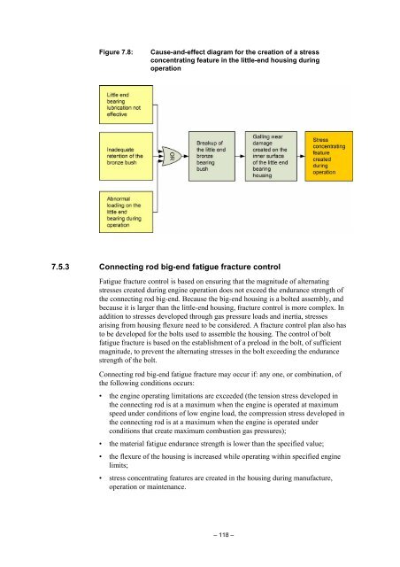
- Page 131: 7.5.2 Connecting rod little-end fat
- Page 135 and 136: Inherent points of stress concentra
- Page 137 and 138: friction is relatively small, so be
- Page 139 and 140: speeds that exceed the design allow
- Page 141 and 142: 8 ANALYSIS OF POWERTRAIN STRUCTURAL
- Page 143 and 144: shockwaves through the gas in the c
- Page 145 and 146: The relationship between engine pow
- Page 147 and 148: Figure 8.5: Cylinder head surface c
- Page 149 and 150: Figure 8.7: Piston surface conditio
- Page 151 and 152: Figure 8.9: Cylinder head surface c
- Page 153 and 154: Figure 8.11: Cylinder head surface
- Page 155 and 156: Figure 8.13: Piston surface conditi
- Page 157 and 158: Figure 8.15: Piston surface conditi
- Page 159 and 160: Figure 8.17: Cylinder head surface
- Page 161 and 162: Figure 8.19: Cylinder head surface
- Page 163 and 164: Figure 8.21: Piston surface conditi
- Page 165 and 166: Lead oxybromide deposits may also f
- Page 167 and 168: The extent of detonation; light, me
- Page 169 and 170: Combustion chamber component temper
- Page 171 and 172: 8.3 Factors associated with bearing
- Page 173 and 174: Any increase in oil-film temperatur
- Page 175 and 176: Figure 8.37: Examples of trimetal b
- Page 177 and 178: phase, in bearings manufactured wit
- Page 179 and 180: emains attached to the aluminium al
- Page 181 and 182: Bearing clearance Bearing clearance
- Page 183 and 184:
Figure 8.48: Detailed view of the n
- Page 185 and 186:
The available connecting-rod bearin
- Page 187 and 188:
Figure 8.52: Detailed view showing
- Page 189 and 190:
8.4 Factors associated with the ret
- Page 191 and 192:
Figure 8.57 Example of insert-locat
- Page 193 and 194:
8.4.3 Crankshaft main-bearing reten
- Page 195 and 196:
Figure 8.62: Detailed view of the m
- Page 197 and 198:
8.5 Factors associated with fatigue
- Page 199 and 200:
• a change in the component has o
- Page 201 and 202:
Figure 8.68: Detailed view of the p
- Page 203 and 204:
8.5.4 Crankshaft fatigue failure Cr
- Page 205 and 206:
Figure 8.74: Schematic showing the
- Page 207 and 208:
8.5.5 Crankshaft fatigue failure -
- Page 209 and 210:
Figure 8.80: Metallographic section
- Page 211 and 212:
Example 2: Teledyne Continental TSI
- Page 213 and 214:
Figure 8.86: Metallographic section
- Page 215 and 216:
Example 4: The Federal Aviation Adm
- Page 217 and 218:
Example 6: Lycoming TIO-540-J2B, oc
- Page 219 and 220:
Figure 8.94: Detailed view of the f
- Page 221 and 222:
Examination of the connecting rod e
- Page 223 and 224:
Planar defects created by journal g
- Page 225 and 226:
Example 10: Lycoming TIO-540-J2BD,
- Page 227 and 228:
Example 11: Lycoming TIO-540-J2BD,
- Page 229 and 230:
Example 13: Lycoming IO-360-A1B6, m
- Page 231 and 232:
Figure 8.114: Detailed views of the
- Page 233 and 234:
Fatigue crack initiation, occurrenc
- Page 235 and 236:
evident, from these sections, that
- Page 237 and 238:
Figure 8.121: Detailed view, sectio
- Page 239 and 240:
Figure 8.124: Fatigue crack initiat
- Page 241 and 242:
8.6 Multiple event sequences It is
- Page 243 and 244:
GAMI, General Aviation Modification
- Page 245 and 246:
9 ANALYSIS OF AIRWORTHINESS ASSURAN
- Page 247 and 248:
Engine reliability (issued December
- Page 249 and 250:
In your letter of 5 August 2002, yo
- Page 251 and 252:
Since August 2001, CASA has receive
- Page 253 and 254:
Lycoming has received several field
- Page 255 and 256:
1. Engines that have complied with
- Page 257 and 258:
ACTION: Final rule. Date: October 2
- Page 259 and 260:
Aggressive leaning: Aggressive lean
- Page 261 and 262:
Feedback is an important component
- Page 263 and 264:
feedback, in response to system mal
- Page 265 and 266:
10 CONCLUSIONS The reliability of r
- Page 267 and 268:
adial-engine combustion chamber (du
- Page 269:
complete certainty, the consequence