Parker Hydraguide steering products - Pirate4x4.Com
Parker Hydraguide steering products - Pirate4x4.Com
Parker Hydraguide steering products - Pirate4x4.Com

You also want an ePaper? Increase the reach of your titles
YUMPU automatically turns print PDFs into web optimized ePapers that Google loves.
Catalog HY13-1553-001/NA,EU<br />
Hydraulics<br />
Hydrostatic Steering Units<br />
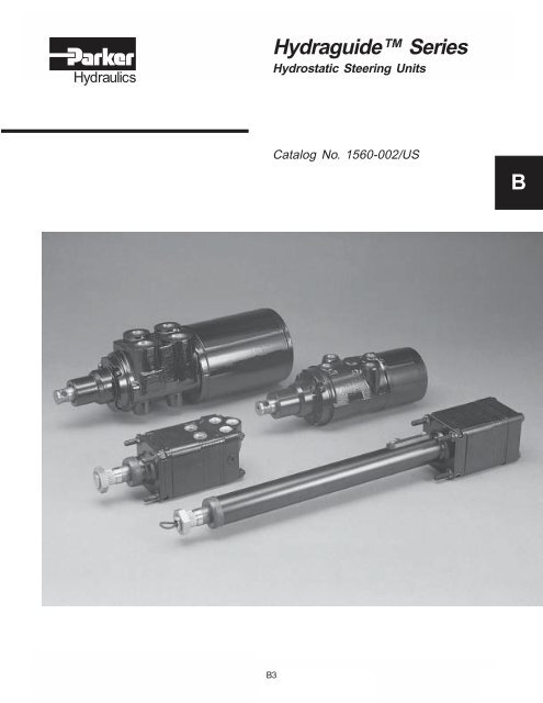
<strong>Hydraguide</strong> Series<br />
Hydrostatic Steering Units<br />
Catalog No. 1560-002/US<br />
B<br />
1560-001_USA.P65, js, bl<br />
Hydraulics<br />
B3<br />
<strong>Parker</strong> Hannifin Corporation<br />
Hydraulic Pump/Motor Division<br />
Greeneville, Tennessee
Catalog HY13-1553-001/NA,EU<br />
Selection Guide<br />
Hydrostatic Steering Units<br />
HGF Series<br />
Open Center<br />
Closed Center<br />
Power Beyond<br />
Operating Parameters:<br />
1800 PSI<br />
8 GPM<br />
3.3 to 9.9 cu. in.<br />
Typical Systems:<br />
Turf, Material Handling, General Purpose,<br />
and Light Agricultural Vehicles.<br />
HGA Series<br />
Open Center<br />
Closed Center<br />
Power Beyond<br />
Load Sense<br />
IN<br />
LT<br />
AUX<br />
Operating Parameters:<br />
2,500 PSI<br />
10 GPM<br />
5.94 to 23.74 cu. in.<br />
OUT<br />
RT<br />
Typical Systems:<br />
Medium Agricultural and Construction<br />
Vehicles.<br />
HGB Series<br />
Open Center<br />
Closed Center<br />
Power Beyond<br />
Load Sense<br />
Operating Parameters:<br />
2,500 PSI<br />
35 GPM<br />
30 to 120 cu. in.<br />
Typical Systems:<br />
Large Agricultural, Mining, and<br />
Construction Vehicles.<br />
LT<br />
OUT<br />
RT<br />
IN<br />
1560-001_USA.P65, js, bl<br />
Hydraulics<br />
B4<br />
<strong>Parker</strong> Hannifin Corporation<br />
Hydraulic Pump/Motor Division<br />
Greeneville, Tennessee
Catalog HY13-1553-001/NA,EU<br />
Selection Guide<br />
Hydrostatic Steering Units<br />
HGF<br />
<strong>Hydraguide</strong> Series 08 10 12 16 20 24<br />
Displacement English 3.30 4.13 4.95 6.60 8.25 9.9<br />
(in 3 /rev) (cm 3 /rev) Metric 54.1 67.7 81.1 108.2 135.2 162.3<br />
Operating Pressure Maximum 1800 1800 1800 1800 1800 1800<br />
(psi) (Bar) 125 125 125 125 125 125<br />
Operating Temperature Maximum 200 200 200 200 200 200<br />
(°F) (°C) 93.3 93.3 93.3 93.3 93.3 93.3<br />
Continuous 8 8 8 8 8 8<br />
Flow Rated 30.3 30.3 30.3 30.3 30.3 30.3<br />
(gpm) (liters/min)<br />
Recommended 1.71 2.15 2.57 3.43 4.29 5.14<br />
(120 rpm) 6.47 8.14 9.73 12.98 16.24 19.45<br />
B<br />
Weight 8.8 9.04 9.28 9.77 10.25 10.75<br />
(lbs) (kg) 3.99 4.10 4.21 4.43 4.65 4.88<br />
“A” Dimensions* 4.37 4.50 4.62 4.87 5.12 5.42<br />
(in) (mm) 111.0 114.2 117.3 123.6 130.0 137.5<br />
HGA<br />
<strong>Hydraguide</strong> Series 08 10 12 14 16 20 24 28 32<br />
Displacement English 5.94 7.42 8.91 10.40 11.88 14.85 17.82 20.79 23.74<br />
(in 3 /rev) (cm 3 /rev) Metric 97.4 121.6 146.0 170.5 194.7 243.4 292.1 340.8 389.1<br />
Operating Pressure Maximum 2500 2500 2500 2500 2500 2500 2500 2500 2500<br />
(psi) (Bar) 175 175 175 175 175 175 175 175 175<br />
Operating Temperature Maximum 200 200 200 200 200 200 200 200 200<br />
(°F) (°C) 93.3 93.3 93.3 93.3 93.3 93.3 93.3 93.3 93.3<br />
Continuous 5 5 5 10 10 10 10 11 12<br />
Flow Rated 18.9 18.9 18.9 37.9 37.9 37.9 37.9 41.6 45.4<br />
(gpm) (liters/min)<br />
Recommended 3.0 4.0 4.5 5.5 6.0 7.5 9.5 11.0 12.0<br />
(120 rpm) 11.4 15.1 17.0 20.8 22.7 28.4 36.0 41.7 45.4<br />
Weight 17.3 17.5 17.7 17.9 18.2 18.5 18.8 19.4 20.0<br />
(lbs) (kg) 7.85 7.94 8.01 8.12 8.26 8.39 8.53 8.80 9.07<br />
“A” Dimensions* 7.09 7.21 7.34 7.46 7.59 7.84 8.09 8.34 8.59<br />
(in) (mm) 180.1 183.1 186.4 189.5 192.8 199.1 205.5 211.8 218.2<br />
HGB<br />
<strong>Hydraguide</strong> Series 16 24 32 40 48 64<br />
Displacement English 30 45 60 75 90 120<br />
(in 3 /rev) (cm 3 /rev) Metric 491.7 737.6 983.4 1229.3 1475.1 1966.8<br />
Operating Pressure Maximum 2500/***3000 2500/***3000 2500/***3000 2500/***3000 2500/***3000 2500/***3000<br />
(psi) (Bar) 175/210 175/210 175/210 175/210 175/210 175/210<br />
Continuous 35 35 35 35 35 35<br />
Flow Rated 132.5 132.5 132.5 132.5 132.5 132.5<br />
(gpm) (liters/min)<br />
Recommended 15.5 23.0 31.0 **35.0 **35.0 **35.0<br />
(120 rpm) 58.7 87.1 117.3 132.5 132.5 132.5<br />
Weight 37.0 40.0 43.0 46.0 49.0 52.0<br />
(lbs) (kg) 16.78 18.14 19.51 20.87 22.23 23.59<br />
“A” Dimensions* 9.77 10.27 10.77 11.27 11.77 12.77<br />
(in) (mm) 248.1 260.8 273.5 286.2 298.9 324.3<br />
* Length from mounting face to end of <strong>Hydraguide</strong> endport only.<br />
** Exceeds rated flow of unit.<br />
*** Special housing for 3000 psi operation available.<br />
1560-001_USA.P65, js, bl<br />
Hydraulics<br />
B5<br />
<strong>Parker</strong> Hannifin Corporation<br />
Hydraulic Pump/Motor Division<br />
Greeneville, Tennessee
Catalog HY13-1553-001/NA,EU<br />
Design Advantages<br />
Hydrostatic Steering Units<br />
<strong>Hydraguide</strong><br />
Each <strong>Hydraguide</strong> unit consists of a directional control valve and metering<br />
section. The valve directs the pressurized oil supplied to and from the<br />
cylinder and the <strong>Hydraguide</strong> metering section. The metering section “meters”<br />
out the pressurized oil to the <strong>steering</strong> cylinder.<br />
The <strong>Hydraguide</strong> works in conjunction with the vehicle’s hydraulic system,<br />
which consists of a <strong>steering</strong> cylinder(s), relief valve, reservoir, filter, fluid<br />
lines, and an engine driven pump to comprise a complete system. The<br />
systems must be tailored to the specific vehicle type and service for which it<br />
will be used. <strong>Parker</strong> offers engineering advice and assistance (and<br />
encourages use of our engineering assistance) when applying hydrostatic<br />
<strong>steering</strong> to any vehicle.<br />
RELIEF<br />
VALVE<br />
RESERVOIR<br />
FILTER<br />
SUPPLY PUMP<br />
CYL.<br />
Typical Steering Circuit<br />
1560-001_USA.P65, js, bl<br />
Hydraulics<br />
B6<br />
<strong>Parker</strong> Hannifin Corporation<br />
Hydraulic Pump/Motor Division<br />
Greeneville, Tennessee
Catalog HY13-1553-001/NA,EU<br />
System Terminology<br />
Hydrostatic Steering Units<br />
Open Center, Nonreversing<br />
The nonreversing unit keeps the steered wheels in the<br />
steered position when the operator releases the <strong>steering</strong><br />
wheel. The cylinder ports are blocked in the neutral<br />
valve position. The operator must steer the wheels<br />
back to the straight ahead position.<br />
Open Center, Reversing<br />
The reversing unit allows the steered wheels to return to<br />
the straight ahead position after the operator releases<br />
the <strong>steering</strong> wheel. This happens only if the <strong>steering</strong><br />
geometry exerts a centering force on the <strong>steering</strong><br />
cylinder. The cylinder ports are interconnected with the<br />
metering section so that the <strong>steering</strong> wheel follows the<br />
wheels back to center position.<br />
B<br />
STRG.<br />
WHL.<br />
STRG.<br />
WHL.<br />
Open Center, Power Beyond (5-line)<br />
The <strong>Hydraguide</strong> has an auxiliary fifth port as a Power<br />
Beyond feature to supply fluid to other functions<br />
downstream of the <strong>Hydraguide</strong> (Circuit #1). The<br />
<strong>Hydraguide</strong> automatically takes priority flow for <strong>steering</strong>,<br />
with the remainder available for auxiliary functions.<br />
When not <strong>steering</strong>, all flow is available to auxiliary<br />
functions. This system eliminates a flow divider or a<br />
separate <strong>steering</strong> circuit, thus saving energy and<br />
component cost.<br />
Open Center, Demand System<br />
This system utilizes a fixed displacement pump, a<br />
priority demand valve to guarantee an adequate amount<br />
of flow to the <strong>steering</strong> unit, a closed center load sense<br />
<strong>steering</strong> unit, and open center auxiliary circuit valves.<br />
STRG.<br />
WHL.<br />
L-S<br />
STEERING<br />
UNIT<br />
AUX CIRCUIT<br />
OPEN CENTER<br />
STRG.<br />
WHL.<br />
PRIORITY<br />
DEMAND<br />
VALVE<br />
PRESSURE/FLOW<br />
COMPENSATED<br />
L-S PUMP<br />
1560-001_USA.P65, js, bl<br />
Hydraulics<br />
B7<br />
<strong>Parker</strong> Hannifin Corporation<br />
Hydraulic Pump/Motor Division<br />
Greeneville, Tennessee
Catalog HY13-1553-001/NA,EU<br />
System Terminology<br />
Hydrostatic Steering Units<br />
Closed Center System<br />
Closed center systems utilize a variable displacement<br />
pump providing variable flow to the <strong>steering</strong> circuit. All<br />
ports of the <strong>Hydraguide</strong> are blocked when the vehicle<br />
is not being steered. The amount of flow through the<br />
<strong>steering</strong> circuit depends upon <strong>steering</strong> speed and<br />
displacement of the <strong>Hydraguide</strong>.<br />
Closed Center, Nonreversing<br />
STRG.<br />
WHL.<br />
TO OTHER<br />
CIRCUITS<br />
Closed Center System with Steering Priority Valve<br />
This system utilizes a variable volume, pressurecompensated<br />
pump, a <strong>steering</strong> priority demand valve, a<br />
closed center load sense <strong>steering</strong> unit, and closed<br />
center auxiliary valves.<br />
Closed Center Load Sense<br />
This unit is a closed center design with a sense line for<br />
actuating the priority valve. Load sense is a flow and<br />
pressure modulation principle that provides a smooth<br />
<strong>steering</strong> transition. The function of the priority valve is<br />
to ensure a supply of power oil to the <strong>steering</strong> unit<br />
regardless of the downstream demand of the auxiliary<br />
valve.<br />
STRG.<br />
WHL.<br />
L-S<br />
STEERING<br />
UNIT<br />
L-S<br />
REMOTE<br />
VALVE<br />
AUX. CIRCUIT<br />
CLOSED CENTER<br />
L-S<br />
STEERING<br />
VALVE<br />
PRIORITY<br />
DEMAND<br />
VALVE<br />
NOTE: If the auxiliary circuit requires a large demand from<br />
the pump, such that an inadequate amount of pump flow is<br />
available for <strong>steering</strong>, then a flow limiting control valve<br />
should be applied to the auxiliary circuit. This is needed to<br />
guarantee <strong>steering</strong> capability under all operating conditions.<br />
PRESSURE/FLOW<br />
COMPENSATED<br />
L-S PUMP<br />
1560-001_USA.P65, js, bl<br />
Hydraulics<br />
B8<br />
<strong>Parker</strong> Hannifin Corporation<br />
Hydraulic Pump/Motor Division<br />
Greeneville, Tennessee
Catalog HY13-1553-001/NA,EU<br />
System Design Process<br />
Hydrostatic Steering Units<br />
Flow Chart<br />
Use the following chart as a guide to design hydrostatic<br />
<strong>steering</strong> systems.<br />
1<br />
Existing System<br />
2<br />
New system where <strong>steering</strong><br />
forces and cylinder stroke(s) are<br />
known.<br />
3<br />
New system where <strong>steering</strong><br />
forces and cylinder stroke(s) are<br />
unknown.<br />
B<br />
Step I Calculate Kingpin Torque<br />
See selection guide for replacement<br />
unit. Choose the closest or<br />
the next smaller standard displacement.<br />
A smaller displacement<br />
provides for faster <strong>steering</strong><br />
speed and more turns lock-to-lock.<br />
If necessary, calculate the new<br />
valves.<br />
Step II Select Steering Unit<br />
Step III Calculate Cylinder Force<br />
Step IV Determine Cylinder Area<br />
Step V Determine Cylinder<br />
Stroke<br />
Step VI Calculate Swept Volume<br />
of Cylinders<br />
Step VII Calculate <strong>Hydraguide</strong><br />
Displacement<br />
Step VIII Calculate Pump Flow<br />
Step IX Measure Maximum<br />
Steering Pressure<br />
Step X Select a Relief Valve<br />
Setting<br />
1560-001_USA.P65, js, bl<br />
Hydraulics<br />
B9<br />
<strong>Parker</strong> Hannifin Corporation<br />
Hydraulic Pump/Motor Division<br />
Greeneville, Tennessee
Catalog HY13-1553-001/NA,EU<br />
System Design Process<br />
Hydrostatic Steering Units<br />
STEP I<br />
mu<br />
.7<br />
.6<br />
.5<br />
.4<br />
.3<br />
.2<br />
.1<br />
Calculate<br />
approximate<br />
Kingpin torque<br />
(KT)<br />
1.1 Determine coefficient<br />
of friction:<br />
Select the coefficient of<br />
friction (mu) from Chart 1<br />
after calculating E/B.<br />
(Kingpin offset/nominal tire<br />
width). See Diagram 1.<br />
Chart 1 (Rubber tires on<br />
dry concrete)<br />
.2 .4 .6 .8 1.0 1.2<br />
E<br />
B<br />
Diagram 1<br />
STEP II<br />
Select <strong>steering</strong><br />
unit<br />
For small garden tractor-type<br />
vehicles, select an HGF —<br />
for larger vehicles select<br />
HGA or HGB. The purpose<br />
of this is to establish what<br />
pressure to use in Step IV.<br />
STEP III Calculate<br />
approximate<br />
cylinder force<br />
(CF)<br />
KT<br />
CF = ——<br />
R<br />
Where:<br />
KT = Kingpin torque<br />
(inch-pounds)<br />
R = Minimum radius<br />
arm (inches)<br />
(see Diagram 2)<br />
Diagram 2<br />
STEP IV Calculate<br />
cylinder area<br />
(CA)<br />
Where:<br />
CF =<br />
CF<br />
CA = ——<br />
P<br />
Cylinder force<br />
(pounds)<br />
P = Pressure (psi)<br />
(This is the<br />
pressure rating of<br />
the <strong>steering</strong> unit<br />
chosen.)<br />
Select the next larger<br />
common cylinder bore size<br />
available. If one cylinder is<br />
used, use the rod end area<br />
only and, if two are used,<br />
use the rod end area plus<br />
the head end area to select<br />
the cylinder (Step VI).<br />
STEP V<br />
Determine<br />
cylinder stroke<br />
Calculate using diagram 2<br />
as a guide and the desired<br />
vehicle turning circle.<br />
STEP VI Calculate<br />
swept volume<br />
(SV) of the<br />
cylinder(s)<br />
6.1. One balanced cylinder,<br />
double acting<br />
SV =<br />
(Bore area - rod<br />
area) x cylinder<br />
stroke<br />
π<br />
SV = — [B 2 - R 2 ] x S<br />
4<br />
f<br />
Minimum Radius<br />
Arm = R<br />
6.2. One unbalanced<br />
cylinder, double acting<br />
B<br />
E<br />
1.2 Calculate Kingpin<br />
torque:<br />
√<br />
_______<br />
B 2<br />
KT= W (mu) — + E<br />
8<br />
2<br />
NOTE: If steered axle<br />
wheels are driven<br />
(powered), double KT.<br />
Stroke<br />
a. Head side<br />
π x B 2<br />
SV = ——— x S<br />
4<br />
b. Rod side<br />
Same as 6.1 above<br />
Where:<br />
KT =<br />
Kingpin torque<br />
in inch-pounds<br />
W = Weight on steered<br />
axle in pounds<br />
(Use maximum<br />
overloaded weight<br />
anticipated.)<br />
mu =<br />
Coefficient of<br />
friction<br />
B = Nominal Tire width<br />
(inches)<br />
E = Kingpin offset<br />
(inches) at the<br />
intersection with<br />
the ground<br />
1560-001_USA.P65, js, bl<br />
Hydraulics<br />
B10<br />
<strong>Parker</strong> Hannifin Corporation<br />
Hydraulic Pump/Motor Division<br />
Greeneville, Tennessee
Catalog HY13-1553-001/NA,EU<br />
System Design Process<br />
Hydrostatic Steering Units<br />
6.3. Two unbalanced<br />
cylinders, double<br />
acting<br />
π x S<br />
SV = ——— (2B 2 - R 2 )<br />
4<br />
Where:<br />
SV =<br />
Swept volume<br />
(volume of oil to<br />
move cylinder full<br />
stroke) in cubic<br />
inches<br />
B = Bore diameter<br />
(inches)<br />
R = Rod diameter<br />
(inches)<br />
S = Cylinder stroke<br />
(inches)<br />
STEP VII Calculate<br />
<strong>Hydraguide</strong><br />
displacement<br />
(HD)<br />
Where:<br />
SV =<br />
SV<br />
HD = ——<br />
n<br />
Swept volume in<br />
cubic inches from<br />
Step VI<br />
n = Number of <strong>steering</strong><br />
wheel turns lock-tolock<br />
(from one end<br />
of cylinder stroke to<br />
the other). This<br />
ranges from 3 to 6<br />
depending on the<br />
type of vehicle.<br />
When one single rod<br />
cylinder is used, calculate n<br />
for each direction because it<br />
will be different. Select the<br />
next closest displacement. If<br />
desired, recalculate n as<br />
follows:<br />
SV<br />
n = ——————————<br />
Displacement of selected<br />
<strong>Hydraguide</strong><br />
STEP VIII<br />
Calculate<br />
minimum<br />
pump flow<br />
(Q)<br />
HD x SS x 60<br />
Q = ——————<br />
231<br />
Where:<br />
Q = Pump flow (gallons/<br />
minutes/<br />
revolutions)<br />
HD = <strong>Hydraguide</strong><br />
displacement<br />
(cubic inches)<br />
SS = Steering speed<br />
(revolutions/<br />
seconds)<br />
(Ideal speed of<br />
steer = 120 rpms.)<br />
Steering Speed<br />
The minimum normally<br />
considered is 1 rev/sec (60<br />
rpm). An example would be<br />
an articulated vehicle. This<br />
depends on the safety<br />
considerations for<br />
avoidance of obstacles<br />
under minimum and<br />
maximum flow conditions<br />
during all speed possibilities<br />
of the vehicle.<br />
1.5 rev/sec (90 rpm) is<br />
common, and 2 rev/sec (120<br />
rpm) is considered about the<br />
maximum input speed<br />
achievable by an average<br />
person.<br />
If the <strong>steering</strong> wheel speed<br />
becomes greater than the<br />
pump flow, a dramatic<br />
increase in <strong>steering</strong> wheel<br />
effort is felt.<br />
STEP IX<br />
Measure<br />
maximum<br />
<strong>steering</strong><br />
pressure<br />
on prototype<br />
vehicle<br />
Compare this pressure with<br />
the pressure rating of the<br />
<strong>Hydraguide</strong>. If it is higher,<br />
return to the last part of Step<br />
III and recalculate through<br />
Step IX again.<br />
STEP X<br />
Select a relief<br />
valve setting<br />
The cracking pressure of the<br />
relief valve, which is usually<br />
defined as the pressure<br />
when the relief valve starts<br />
to open and discharge flow<br />
to the return line, should be<br />
greater than the maximum<br />
pressure measured on the<br />
vehicle.<br />
The full flow pressure of the<br />
relief valve, which is defined<br />
as the pressure when<br />
maximum flow is going over<br />
the relief valve, must not<br />
exceed the pressure rating<br />
on the <strong>steering</strong> unit.<br />
NOTE:<br />
Reversing units used with<br />
balanced area cylinders.<br />
B<br />
1560-001_USA.P65, js, bl<br />
Hydraulics<br />
B11<br />
<strong>Parker</strong> Hannifin Corporation<br />
Hydraulic Pump/Motor Division<br />
Greeneville, Tennessee
Catalog HY13-1553-001/NA,EU<br />
Introduction<br />
Hydrostatic Steering Units<br />
HGF Series<br />
<strong>Hydraguide</strong> brand hydrostatic <strong>steering</strong> units were developed to meet<br />
the requirements of a broad range of off-highway applications. The HGF<br />
series is designed for light duty applications such as lawn and garden<br />
equipment, small agricultural equipment, small off-highway vehicles and<br />
material handling equipment.<br />
HGF Series Features<br />
• Compact Size—The compact size of the HGF permits mounting in<br />
tight spaces to add overall machine design flexibility.<br />
• Full-Pressure Shaft Seal—The <strong>Parker</strong> full pressure input shaft seal is<br />
able to withstand full system back pressure up to the pressure rating<br />
of the <strong>Hydraguide</strong>. This enables operation of auxiliary hydraulic<br />
functions downstream of <strong>steering</strong>.<br />
• Pressure Dams—Pressure dams provide a barrier of pressurized<br />
system oil between metered oil and return. Pressure dam valving<br />
provides more precise <strong>steering</strong> due to the reduction of leakage oil<br />
from the metering element.<br />
• Needle Thrust Bearing—The needle trust bearing reduces input<br />
torque required to steer, resulting in lower <strong>steering</strong> efforts.<br />
• SAE #6 Female O-Ring Ports Standard.<br />
• Integral Mounting Studs—Integral mounting bolts minimize<br />
hardware cost and simplify installation, resulting in fewer service<br />
parts.<br />
• Manual Emergency Steering—A ball check valve allows manual<br />
<strong>steering</strong> in emergencies when pump flow is interrupted. If the vehicle<br />
is large enough to require more that 100 ft.-lb. <strong>steering</strong> wheel torque<br />
in the manual mode, another means of emergency <strong>steering</strong> is<br />
recommended.<br />
• Integral Relief Available—Five pressure settings from 500 to 1740 psi.<br />
Preset to protect <strong>steering</strong> unit from excessive system pressure.<br />
1560-001_USA.P65, js, bl<br />
Hydraulics<br />
B12<br />
<strong>Parker</strong> Hannifin Corporation<br />
Hydraulic Pump/Motor Division<br />
Greeneville, Tennessee
Catalog HY13-1553-001/NA,EU<br />
Specifications<br />
Hydrostatic Steering Units<br />
HGF Series<br />
HGF<br />
<strong>Hydraguide</strong> Series 08 10 12 16 20 24<br />
Displacement English 3.30 4.13 4.95 6.60 8.25 9.9<br />
(in 3 /rev) (cm 3 /rev) Metric 54.1 67.7 81.1 108.2 135.2 162.3<br />
Operating Pressure Maximum 1800 1800 1800 1800 1800 1800<br />
(psi) (Bar) 125 125 125 125 125 125<br />
Operating Temperature Maximum 200 200 200 200 200 200<br />
(°F) (°C) 93.3 93.3 93.3 93.3 93.3 93.3<br />
Continuous 8 8 8 8 8 8<br />
Flow Rated 30.3 30.3 30.3 30.3 30.3 30.3<br />
(gpm) (liters/min)<br />
Recommended 2 1.71 2.15 2.57 3.43 4.29 5.14<br />
(120 rpm) 6.47 8.14 9.73 12.98 16.24 19.45<br />
B<br />
Weight 8.8 9.04 9.28 9.77 10.25 10.75<br />
(lbs) (kg) 3.99 4.10 4.21 4.43 4.65 4.88<br />
“A” Dimensions 3 4.37 4.50 4.62 4.87 5.12 5.42<br />
(in) (mm) 111.0 114.2 117.3 123.6 130.0 137.5<br />
“B” Dimensions 5.3 5.4 5.6 5.8 6.1 6.4<br />
(in) (mm) 134.6 137.1 142.2 147.3 154.9 162.6<br />
1<br />
English dimensions are control values; metric values are conversions.<br />
2<br />
For two handwheel turns per second.<br />
3<br />
Length from mounting face to end of <strong>Hydraguide</strong> end.<br />
Fluid/Filtration<br />
Automatic transmission fluid (ATF) or<br />
contact your <strong>Parker</strong> Sales Engineer<br />
for other fluid recommendations.<br />
Use 20-50 micrometer nominal<br />
filtration.<br />
120<br />
100<br />
80<br />
HGF Delta P -vs- Flow at 130° F (54.5° C) (113 SUS)<br />
Inlet Flow (LPM)<br />
4 8 11 15 18 23 26 30 34 38<br />
8.3<br />
6.9<br />
5.5<br />
(PSI)<br />
60<br />
4.1<br />
(BAR)<br />
40<br />
20<br />
2.8<br />
1.4<br />
1 2 3 4 5 6 7 8 9 10<br />
Inlet Flow (GPM)<br />
1560-001_USA.P65, js, bl<br />
Hydraulics<br />
B13<br />
<strong>Parker</strong> Hannifin Corporation<br />
Hydraulic Pump/Motor Division<br />
Greeneville, Tennessee
3.05<br />
(77.5)<br />
Catalog HY13-1553-001/NA,EU<br />
Dimensions<br />
HGF Open Center HGF Power Beyond<br />
(HGFXX2X0) (HGFXX2X6)<br />
LT<br />
RT<br />
OUT<br />
LT<br />
RT<br />
OUT<br />
AUX<br />
Hydrostatic Steering Units<br />
HGF Series<br />
"A" LENGTH 1.00<br />
(25.4)<br />
45˚±0˚30'<br />
TYP<br />
IN<br />
72˚<br />
IN<br />
9/16-18 Strght. Thd.<br />
SAE #6 Female O-Ring Ports<br />
on a 1.66 [42.16] Dia. Circle<br />
(4) 5/16-24 UNF-2A Thread Studs<br />
Equally Spaced & Located On A<br />
Ø3.250 [82.55] Circle Within<br />
R.005 [0.13]Of O<br />
3.045 (77.3)<br />
MAX TYP<br />
“A” Dimensions<br />
Series 08 10 12 16 20 24<br />
(in) 4.16 4.28 4.41 4.66 4.91 5.16<br />
(mm) 105.7 108.7 112.0 118.4 124.7 131.1<br />
HGF Open Center Sideport<br />
(HGFXX4X0)<br />
1.25 [31,8]<br />
.62 [15,7]<br />
.56 [14,2]<br />
2.76 [70,1]<br />
Dimension “B”<br />
AUX<br />
OUT<br />
IN<br />
LT RT<br />
1.00<br />
(25.4)<br />
This Port Pressurized<br />
When Shaft is Rotated<br />
Clockwise.<br />
9/16-18 Straight THD O-Ring Ports<br />
“B” Dimensions<br />
Series 08 10 12 16 20 24<br />
(in) 5.38 5.50 5.63 5.88 6.13 6.38<br />
(mm) 136.6 139.7 143.0 149.3 155.7 162.1<br />
(4) 5/16-24 UNF-2A Thread Studs.<br />
Equally Spaced & Located on a<br />
Ø3.250 [82,55] Circle Within<br />
R.005 [0,13] of<br />
3.17 (80.5)<br />
Max<br />
45˚±0˚30'<br />
TYP<br />
Note:<br />
1. All dimensions are for reference only.<br />
2. Add .50 in (12.7 mm) for integral relief.<br />
Porting option 2 only)<br />
3. Reversing units shall be used with<br />
balanced area cylinders.<br />
Adapter Fittings<br />
411085-A1 411090-A1<br />
Straight Thread SAE #6 O-Ring<br />
Male JIC 37 o Flare<br />
Straight Thread SAE #6 O-Ring<br />
<strong>Parker</strong> Seal-Lok 9/16 x 18<br />
1560-001_USA.P65, js, bl<br />
Hydraulics<br />
B14<br />
<strong>Parker</strong> Hannifin Corporation<br />
Hydraulic Pump/Motor Division<br />
Greeneville, Tennessee
Catalog HY13-1553-001/NA,EU<br />
Hydrostatic Steering Units<br />
HGF Series<br />
HGF Power Beyond Sideport<br />
(HGFXX4X6)<br />
1.25 [31,8]<br />
.51 [13,0]<br />
.62 [15,7]<br />
Dimension “B”<br />
(4) 5/16-24 UNF-2A Thread Studs.<br />
Equally Spaced & Located on a<br />
2.76 [70,1] 1.00<br />
(25.4)<br />
Ø3.250 [82,55] Circle Within<br />
R.005 [0,13] of<br />
AUX<br />
OUT<br />
IN<br />
LT RT<br />
3.17 (80.5)<br />
Max<br />
45˚±0˚30'<br />
TYP<br />
B<br />
.56 [14,2]<br />
This Port Pressurized<br />
When Shaft is Rotated<br />
Clockwise.<br />
9/16-18 Straight Thd.<br />
SAE #6 O-Ring Ports (5)<br />
on a 1.66 (42.16) Dia. Circle<br />
Note:<br />
1. All dimensions are for reference only.<br />
2. Add .50 in (12.7 mm) for integral relief.<br />
Porting option 2 only)<br />
3. Reversing units shall be used with<br />
balanced area cylinders.<br />
“B” Dimensions<br />
Series 08 10 12 16 20 24<br />
(in) 5.38 5.50 5.63 5.88 6.13 6.38<br />
(mm) 136.6 139.7 143.0 149.3 155.7 162.1<br />
HGF Tilt Column<br />
HTC01750<br />
• 5 positions<br />
• 40 o range of adjustment<br />
• 3/4 x 40 serrations<br />
• Can be mounted to end or side ported units<br />
1560-001_USA.P65, js, bl<br />
Hydraulics<br />
B15<br />
<strong>Parker</strong> Hannifin Corporation<br />
Hydraulic Pump/Motor Division<br />
Greeneville, Tennessee
Catalog HY13-1553-001/NA,EU<br />
Columns<br />
Hydrostatic Steering Units<br />
HGF Series<br />
Standard Column<br />
.89<br />
REF<br />
“B” Length<br />
1.38 .50<br />
1.60<br />
.858 Dia.<br />
Gage<br />
.156<br />
.623 Taper<br />
Per Foot<br />
.875 x 36<br />
Strght. Serrations<br />
13/16-20<br />
UNF-2A Thd.<br />
Hornwire Column<br />
(Single or Dual Contact)<br />
.89<br />
REF<br />
“B” Length<br />
1.00 1.38 .50<br />
4.00<br />
.50<br />
1.60<br />
.858 Dia.<br />
Gage<br />
.156 2.13<br />
.623 Taper<br />
Per Foot<br />
.875 x 36<br />
Strght. Serrations<br />
13/16-20<br />
UNF-2A Thd.<br />
Notes:<br />
1. All dimensions are for reference only.<br />
2. Jacket tube diameter of all columns is 1.50 inches.<br />
3. Column support is required for columns longer than 10 inches.<br />
4. For “B” length see HGF Steering Column Selection Chart, page C16.<br />
1560-001_USA.P65, js, bl<br />
Hydraulics<br />
B16<br />
<strong>Parker</strong> Hannifin Corporation<br />
Hydraulic Pump/Motor Division<br />
Greeneville, Tennessee
Catalog HY13-1553-001/NA,EU<br />
Steering Column Selection<br />
Hydrostatic Steering Units<br />
HGF Series<br />
HGF<br />
Part Number “B” Length - in (mm) Specification<br />
Standard SKF00078-0400 4 (101.6) 7/8" x 36; no horn contact<br />
SKF00078-0600 6 (152.4) 7/8" x 36; no horn contact<br />
SKF00078-0800 8 (203.2) 7/8" x 36; no horn contact<br />
SKF00078-1200 12 (304.8) 7/8" x 36; no horn contact<br />
SKF00078-1600 16 (406.4) 7/8" x 36; no horn contact<br />
SKF00078-2200 22 (558.8) 7/8" x 36; no horn contact<br />
SKF00078-2400 24 (609.6) 7/8" x 36; no horn contact<br />
SKF00078-3200 32 (812.8) 7/8" x 36; no horn contact<br />
SKF00078-3450 34.5 (876.3) 7/8" x 36; no horn contact<br />
Single Hornwire SKF00178-0800 8 (203.2) 7/8" x 36; single horn contact<br />
SKF00178-1200 12 (304.8) 7/8" x 36; single horn contact<br />
SKF00178-1600 16 (406.4) 7/8" x 36; single horn contact<br />
SKF00178-2400 24 (609.6) 7/8" x 36; single horn contact<br />
SKF00178-3200 32 (812.8) 7/8" x 36; single horn contact<br />
Dual Hornwire SKF00278-0800 8 (203.2) 7/8" x 36; dual horn contact<br />
SKF00278-1200 12 (304.8) 7/8" x 36; dual horn contact<br />
SKF00278-1600 16 (406.4) 7/8" x 36; dual horn contact<br />
SKF00278-2400 24 (609.6) 7/8" x 36; dual horn contact<br />
SKF00278-3200 32 (812.8) 7/8" x 36; dual horn contact<br />
B<br />
HGF<br />
Part Number “B” Length - in (mm) Specification<br />
Standard SKF00034-0400 4 (101.6) 3/4" x 40; no horn contact<br />
SKF00034-0600 6 (152.4) 3/4" x 40; no horn contact<br />
SKF00034-0800 8 (203.2) 3/4" x 40; no horn contact<br />
SKF00034-1200 12 (304.8) 3/4" x 40; no horn contact<br />
SKF00034-1600 16 (406.4) 3/4" x 40; no horn contact<br />
SKF00034-2200 22 (558.8) 3/4" x 40; no horn contact<br />
SKF00034-2400 24 (609.6) 3/4" x 40; no horn contact<br />
SKF00034-3200 32 (812.8) 3/4" x 40; no horn contact<br />
SKF00034-3450 34.5 (876.3) 3/4" x 40; no horn contact<br />
Single Hornwire SKF00134-0800 8 (203.2) 3/4" x 40; single horn contact<br />
SKF00134-1200 12 (304.8) 3/4" x 40; single horn contact<br />
SKF00134-1600 16 (406.4) 3/4" x 40; single horn contact<br />
SKF00134-2400 24 (609.6) 3/4" x 40; single horn contact<br />
SKF00134-3200 32 (812.8) 3/4" x 40; single horn contact<br />
Dual Hornwire SKF00234-0800 8 (203.2) 3/4" x 40; dual horn contact<br />
SKF00234-1200 12 (304.8) 3/4" x 40; dual horn contact<br />
SKF00234-1600 16 (406.4) 3/4" x 40; dual horn contact<br />
SKF00234-2400 24 (609.6) 3/4" x 40; dual horn contact<br />
SKF00234-3200 32 (812.8) 3/4" x 40; dual horn contact<br />
Notes:<br />
1. Steering wheel horn button not included in<br />
column kits. Order part number 465611<br />
separately.<br />
2. Steering wheel nut included with column.<br />
3. For column lengths or horn wires not<br />
shown above, contact your <strong>Parker</strong> Sales<br />
Engineer.<br />
1560-001_USA.P65, js, bl<br />
Hydraulics<br />
B17<br />
<strong>Parker</strong> Hannifin Corporation<br />
Hydraulic Pump/Motor Division<br />
Greeneville, Tennessee
Catalog HY13-1553-001/NA,EU<br />
Model Number Explanation<br />
Hydrostatic Steering Units<br />
HGF Series<br />
<strong>Hydraguide</strong> Series<br />
HGF<br />
X X<br />
X X X<br />
HGF<br />
Displacement<br />
XX in 3 /rev cm 3 /rev<br />
08 3.30 54.1<br />
10 4.13 67.7<br />
12 4.95 81.1<br />
16 6.60 108.2<br />
20 8.25 135.2<br />
24 9.90 162.3<br />
X System Type<br />
0 Open Center Nonreversing<br />
1* Open Center Nonreversing<br />
(low noise)<br />
2 Open Center Reversing<br />
6 Power Beyond Nonreversing<br />
3 Power Beyond Reversing<br />
4 Closed Center Nonreversing<br />
7 Closed Center Reversing<br />
* Only available with port option 2<br />
X<br />
Porting<br />
2 Female #6<br />
SAE O-Ring<br />
4 Female #6 SAE O-Ring<br />
Side Port<br />
X<br />
Relief Option<br />
2 No Relief<br />
4 921 psi (64 Bar)<br />
7 1200 psi (83 Bar)<br />
6 1560 psi (108 Bar)<br />
8 1740 psi (120 Bar)<br />
P<br />
R<br />
Example:<br />
HGF08220 signifies HGF <strong>Hydraguide</strong><br />
series unit with 3.30 in 3 /rev<br />
displacement, open center,<br />
nonreversing with female<br />
#6 SAE O-Ring ports.<br />
1560-001_USA.P65, js, bl<br />
Hydraulics<br />
B18<br />
<strong>Parker</strong> Hannifin Corporation<br />
Hydraulic Pump/Motor Division<br />
Greeneville, Tennessee
Catalog HY13-1553-001/NA,EU<br />
Introduction<br />
Hydrostatic Steering Units<br />
HGA/HGB Series<br />
The HGA and HGB series <strong>Hydraguide</strong> <strong>steering</strong> units are designed for<br />
applications such as large agricultural equipment including tractors, combines<br />
and other self-propelled, specialized harvesting equipment. In addition, these<br />
units are frequently specified for many medium-to-heavy-duty applications such<br />
as logging and construction equipment and marine and mining applications.<br />
B<br />
HGA/HGB Series Features<br />
• Full Pressure Shaft Seal—The <strong>Parker</strong> full pressure input shaft seal is able to withstand full system back<br />
pressure up to the pressure rating of the <strong>Hydraguide</strong>. This enables operation of auxiliary hydraulic functions<br />
downstream of <strong>steering</strong>.<br />
• Linear Valve Spool—The linear valve spool is less subject to stick and damage in the event of system<br />
contamination and allows generally better control.<br />
• Pressure Dams—Pressure dams provide a barrier of pressurized system oil between metered oil and return.<br />
Pressure dam valving provides more precise <strong>steering</strong> due to the reduction of lost leakage oil from the<br />
metering element.<br />
• Vaned Rotor (HGA Only)—The spring biased vanes in the rotor tips reduce leakage between pockets in the<br />
metering group. This provides more precise and positive <strong>steering</strong>.<br />
• Pressure Balanced Metering Group—All <strong>Parker</strong> designs utilize a pressurized envelope around the metering<br />
package (rotor set—commutator) to reduce slippage leakage and provide more precise <strong>steering</strong> control.<br />
• Manual Emergency Steering—A ball check valve allows manual <strong>steering</strong> in emergencies when pump flow is<br />
interrupted. If the vehicle is large enough to require more than 100 ft.-lb. <strong>steering</strong> wheel torque in the<br />
manual mode, another means of emergency <strong>steering</strong> is recommended.<br />
1560-001_USA.P65, js, bl<br />
Hydraulics<br />
B19<br />
<strong>Parker</strong> Hannifin Corporation<br />
Hydraulic Pump/Motor Division<br />
Greeneville, Tennessee
Catalog HY13-1553-001/NA,EU<br />
Specifications<br />
Hydrostatic Steering Units<br />
HGA/HGB Series<br />
HGA<br />
<strong>Hydraguide</strong> Series 08 10 12 14 16 20 24 28 32<br />
Displacement English 1 5.94 7.42 8.91 10.40 11.88 14.85 17.82 20.79 23.74<br />
(in 3 /rev) (cm 3 /rev) Metric 97.4 121.6 146.0 170.5 194.7 243.4 292.1 340.7 389.1<br />
Operating Pressure Maximum 2500 2500 2500 2500 2500 2500 2500 2500 2500<br />
(psi) (Bar) 175 175 175 175 175 175 175 175 175<br />
Operating Temperature Maximum 200 200 200 200 200 200 200 200 200<br />
(°F) (°C) 93.3 93.3 93.3 93.3 93.3 93.3 93.3 93.3 93.3<br />
Continuous 5 5 5 10 10 10 10 11 12<br />
Flow Rated 18.9 18.9 18.9 37.9 37.9 37.9 37.9 41.6 45.4<br />
(gpm) (liters/min)<br />
Recommended 2 3.0 4.0 4.5 5.5 6.0 7.5 9.5 11.0 12.0<br />
(120 rpm) 11.4 15.1 17.0 20.8 22.7 28.4 36.0 41.7 45.4<br />
Weight 17.3 17.5 17.7 17.9 18.2 18.5 18.8 19.4 20.0<br />
(lbs) (kg) 7.85 7.94 8.01 8.12 8.26 8.39 8.53 8.80 9.07<br />
"A" Dimensions 3 7.09 7.21 7.34 7.46 7.59 7.84 8.09 8.34 8.59<br />
(in) (mm) 180.1 183.1 186.4 189.5 192.8 199.1 205.5 211.8 218.2<br />
1<br />
English dimensions are control values; metric values are conversions.<br />
2<br />
For two handwheel turns per second.<br />
3<br />
Length from mounting face to end of <strong>Hydraguide</strong>.<br />
Fluid/Filtration<br />
Automatic transmission fluid (ATF) or<br />
contact your <strong>Parker</strong> Sales Engineer<br />
for other fluid recommendations.<br />
Use 20-50 micrometer nominal<br />
filtration.<br />
120<br />
100<br />
HGA Delta P -vs- Flow at<br />
130° F (54.5° C) (113 SUS)<br />
Inlet Flow (LPM)<br />
4 8 11 15 18 23 26 30 34 38<br />
8.3<br />
6.9<br />
80<br />
5.5<br />
(PSI)<br />
60<br />
40<br />
LOW FLOW<br />
HIGH FLOW<br />
4.1<br />
2.8<br />
(BAR)<br />
20<br />
1.4<br />
1 2 3 4 5 6 7 8 9 10<br />
Inlet Flow (GPM)<br />
Note:<br />
Option 1: Use low flow unit for 5 GPM or less.<br />
Option 2: Use high flow unit for 5 to 10 GPM.<br />
1560-001_USA.P65, js, bl<br />
Hydraulics<br />
B20<br />
<strong>Parker</strong> Hannifin Corporation<br />
Hydraulic Pump/Motor Division<br />
Greeneville, Tennessee
Catalog HY13-1553-001/NA,EU<br />
Dimensions<br />
Hydrostatic Steering Units<br />
HGA Series<br />
Open Center<br />
"A" See Chart<br />
4.37<br />
3.55<br />
See Input<br />
Shaft Page<br />
1.78<br />
2.20<br />
1.22<br />
2.38<br />
LT<br />
1.34<br />
25˚<br />
3.57 Dia.<br />
1.16<br />
1.06<br />
IN<br />
OUT<br />
AUX<br />
RT<br />
1.645<br />
Dia.<br />
2.125<br />
2.115<br />
Pilot Dia.<br />
5/16-18 UNC-2B Thd.<br />
4 Holes Equally Spaced<br />
on a 2.875 Dia. Bolt Circle<br />
Mounting Screw Engagement<br />
Must Not Exceed .48<br />
B<br />
SAE 9/16-18 Strght. Thd.<br />
O-Ring Ports (4)<br />
This Port Pressurized When<br />
Input Shaft is Rotated Clockwise<br />
Load Sense<br />
"A" See Chart<br />
4.37<br />
3.55<br />
See Input<br />
Shaft Page<br />
1.78<br />
2.20<br />
1.22<br />
2.38<br />
LT<br />
1.34<br />
25˚<br />
3.57 Dia.<br />
1.16<br />
1.06<br />
LS<br />
OUT<br />
IN<br />
RT<br />
1.645<br />
Dia.<br />
2.125<br />
2.115<br />
Pilot Dia.<br />
5/16-18 UNC-2B Thd.<br />
4 Holes Equally Spaced<br />
on a 2.875 Dia. Bolt Circle<br />
Mounting Screw Engagement<br />
Must Not Exceed .48<br />
SAE 9/16-18 Strght. Thd.<br />
O-Ring Ports (5)<br />
This Port Pressurized When<br />
Input Shaft is Rotated Clockwise<br />
“A” Dimensions<br />
Series 08 10 12 14 16 20 24 28 32<br />
(in) 7.09 7.21 7.34 7.46 7.59 7.84 8.09 8.34 8.59<br />
(mm) 180.1 183.1 186.4 189.5 192.8 199.1 205.5 211.8 218.2<br />
Note:<br />
1. All dimensions are for reference only.<br />
2. Mounting screw engagement must not exceed .48.<br />
3. Low flow units are used with 5 GPM or less flow from pump.<br />
4. High flow units are used with more than 5 GPM flow from pump.<br />
5. Reversing units should be used with balanced area cylinders.<br />
1560-001_USA.P65, js, bl<br />
Hydraulics<br />
B21<br />
<strong>Parker</strong> Hannifin Corporation<br />
Hydraulic Pump/Motor Division<br />
Greeneville, Tennessee
Catalog HY13-1553-001/NA,EU<br />
Dimensions<br />
Hydrostatic Steering Units<br />
HGA Series<br />
Power Beyond<br />
"A" See Chart<br />
4.37<br />
3.55<br />
See Input<br />
Shaft Page<br />
1.78<br />
2.96<br />
2.20<br />
1.22<br />
2.38<br />
1.34<br />
25°<br />
LT<br />
3.57 Dia.<br />
1.16<br />
1.06<br />
IN<br />
AUX<br />
OUT<br />
RT<br />
1.645<br />
Dia.<br />
Plugged on<br />
Closed Center Unit<br />
2.125<br />
2.115<br />
Pilot Dia.<br />
5/16-18 UNC-2B Thd.<br />
4 Holes Equally Spaced<br />
on a 2.875 Dia. Bolt Circle<br />
Mounting Screw Engagement<br />
Must Not Exceed .48<br />
SAE 9/16-18 Strght. Thd.<br />
O-Ring Ports (5)<br />
This Port Pressurized When<br />
Input Shaft is Rotated Clockwise<br />
“A” Dimensions<br />
Series 08 10 12 14 16 20 24 28 32<br />
(in) 7.09 7.21 7.34 7.46 7.59 7.84 8.09 8.34 8.59<br />
(mm) 180.1 183.1 186.4 189.5 192.8 199.1 205.5 211.8 218.2<br />
Note:<br />
1. All dimensions are for reference only.<br />
2. Mounting screw engagement must not exceed .48.<br />
3. Low flow units are used with 5 GPM or less flow from pump.<br />
4. High flow units are used with more than 5 GPM flow from pump.<br />
1560-001_USA.P65, js, bl<br />
Hydraulics<br />
B22<br />
<strong>Parker</strong> Hannifin Corporation<br />
Hydraulic Pump/Motor Division<br />
Greeneville, Tennessee
Catalog HY13-1553-001/NA,EU<br />
Columns<br />
Hydrostatic Steering Units<br />
HGA Series<br />
Column Mount<br />
3.45<br />
3.02<br />
.874<br />
.875 Dia.<br />
Direct Wheel Mount<br />
4.06<br />
2.115<br />
2.125 Dia.<br />
2.115<br />
2.125 Dia.<br />
Standard Column<br />
.372<br />
.374 Dia.<br />
.875 x 36 Strght.<br />
Serrations<br />
Hornwire Column<br />
B<br />
"B" Length<br />
To Suit<br />
Wheel<br />
"W"<br />
.50<br />
5.62*<br />
"B" Length<br />
To Suit<br />
Wheel<br />
"W" .50<br />
.858 Dia.<br />
Gage<br />
1.75 Dia.<br />
.623 Taper<br />
Per Foot<br />
.875 x 36 Strght.<br />
Serrations<br />
13/16-20<br />
UNEF-2A Thd.<br />
.875 x 36 Strght.<br />
Serrations<br />
* Dimension is 4.62 for SK000014-1075 Column<br />
Full Bolt Groove Shaft<br />
4.06<br />
.812<br />
1.43<br />
2.115<br />
2.125 Dia.<br />
.875 x 36 Strght.<br />
Serrations<br />
Notes:<br />
1. All dimensions are for reference only.<br />
2. Diameter of all columns is 1.75 inches.<br />
3. Column support is required for columns<br />
longer than 14.25 inches.<br />
4. Contact brush, screws, wheelnuts and<br />
spacer for horn button contact are<br />
assembled by customer.<br />
5. For 'B' length see HGA Steering Column<br />
Selection Chart, page C29.<br />
1560-001_USA.P65, js, bl<br />
Hydraulics<br />
B23<br />
<strong>Parker</strong> Hannifin Corporation<br />
Hydraulic Pump/Motor Division<br />
Greeneville, Tennessee
Catalog HY13-1553-001/NA,EU<br />
Specifications<br />
Hydrostatic Steering Units<br />
HGB Series<br />
HGB<br />
<strong>Hydraguide</strong> Series 16 24 32 40 48 64<br />
Displacement English 1 30 45 60 75 90 120<br />
(in 3 /rev) (cm 3 /rev) Metric 491.7 737.6 983.4 1229.3 1475.1 1966.8<br />
Operating Pressure Maximum 2500/3000 4 2500/3000 4 2500/3000 4 2500/3000 4 2500/3000 4 2500/3000 4<br />
(psi) (Bar) 175/210 175/210 175/210 175/210 175/210 175/210<br />
Operating Temperature Maximum 200 200 200 200 200 200<br />
(°F) (°C) 93.3 93.3 93.3 93.3 93.3 93.3<br />
Continuous 35 35 35 35 35 35<br />
Flow Rated 132.5 132.5 132.5 132.5 132.5 132.5<br />
(gpm) (liters/min)<br />
Recommended 2 15.5 23.0 31.0 **35.0 **35.0 **35.0<br />
(120 rpm) 58.7 87.1 117.3 132.5 132.5 132.5<br />
Weight 37.0 40.0 43.0 46.0 49.0 52.0<br />
(lbs) (kg) 16.78 18.14 19.51 20.87 22.23 23.59<br />
“A” Dimensions 3 9.77 10.27 10.77 11.27 11.77 12.77<br />
(in) (mm) 248.1 260.8 273.5 286.2 298.9 324.3<br />
1<br />
English dimensions are control values; metric values are conversions.<br />
2<br />
For two handwheel turns per second.<br />
3<br />
Length from mounting face to end of <strong>Hydraguide</strong>.<br />
4<br />
Special housing for 3000 psi operation available.<br />
Fluid/Filtration<br />
Automatic transmission fluid (ATF) or<br />
contact your <strong>Parker</strong> Sales Engineer<br />
for other fluid recommendations.<br />
120<br />
HGB Delta P -vs- Flow at<br />
130° F (54.5° C) (113 SUS)<br />
Inlet Flow (LPM)<br />
19 39 57 76 95 114 132 151<br />
8.3<br />
Use 20-50 micrometer nominal<br />
filtration.<br />
110<br />
100<br />
90<br />
80<br />
7.6<br />
6.9<br />
6.2<br />
5.5<br />
High Flow or<br />
Low Flow<br />
(PSI)<br />
70<br />
4.8<br />
(BAR)<br />
60<br />
4.1<br />
50<br />
3.4<br />
40<br />
2.8<br />
30<br />
2.1<br />
20<br />
1.4<br />
10<br />
.7<br />
5 10 15 20 25 30 35 40<br />
Inlet Flow (GPM)<br />
Note:<br />
Option 1: Use low flow unit for 5 GPM or less.<br />
Option 2: Use high flow unit for 5 to 10 GPM.<br />
1560-001_USA.P65, js, bl<br />
Hydraulics<br />
B24<br />
<strong>Parker</strong> Hannifin Corporation<br />
Hydraulic Pump/Motor Division<br />
Greeneville, Tennessee
Catalog HY13-1553-001/NA,EU<br />
Dimensions<br />
Hydrostatic Steering Units<br />
HGB Series<br />
Open Center<br />
SAE 1 1/16-12<br />
Strght. Thd.<br />
O-Ring Ports (2)<br />
"A" See Chart<br />
4.21<br />
See Input<br />
Shaft Page<br />
2.38<br />
1.96 1.34<br />
2.46 1.84<br />
5.00 Dia.<br />
1.25<br />
1.12<br />
LT<br />
OUT<br />
RT<br />
IN<br />
1.645 Dia.<br />
2.125<br />
2.115<br />
B<br />
SAE 7/8-14<br />
Strght. Thd.<br />
O-Ring Ports (2)<br />
4.75<br />
2.62<br />
1.12<br />
2.25<br />
3.81<br />
2.25<br />
3/8-16 UNC-2B thd.<br />
.62 Deep (4 Holes)<br />
(Unit Must Be Mounted<br />
on These Bosses)<br />
“A” Dimensions<br />
Series 16 24 32 40 48 64<br />
(in) 9.77 10.27 10.77 11.27 11.77 12.77<br />
(mm) 248.1 260.8 273.5 286.2 298.9 324.3<br />
Note:<br />
1. All dimensions are for reference only.<br />
2. Reversing units should be used with balanced area cylinders.<br />
1560-001_USA.P65, js, bl<br />
Hydraulics<br />
B25<br />
<strong>Parker</strong> Hannifin Corporation<br />
Hydraulic Pump/Motor Division<br />
Greeneville, Tennessee
Catalog HY13-1553-001/NA,EU<br />
Dimensions<br />
Hydrostatic Steering Units<br />
HGB Series<br />
Power Beyond<br />
SAE 1 1/16-12<br />
Strght. Thd.<br />
O-Ring Ports (2)<br />
"A" See Chart<br />
4.21<br />
See Input<br />
Shaft Page<br />
2.38<br />
1.96 1.34<br />
2.46 1.84<br />
5.00 Dia.<br />
1.25<br />
1.12<br />
LT<br />
OUT<br />
RT<br />
IN<br />
1.645 Dia.<br />
2.125<br />
2.115<br />
2.64<br />
AUX<br />
SAE 7/8-14<br />
Strght. Thd.<br />
O-Ring Ports (2)<br />
2.62<br />
3.69<br />
SAE 1-1/16-12 Strght.<br />
Thd. O-Ring Port<br />
1.53<br />
SAE 1-1/16-12 Strght.<br />
Thd. O-Ring Port<br />
4.75<br />
2.25<br />
1.12<br />
2.25<br />
3/8-16 UNC-2B thd<br />
.62 Deep (4 Holes)<br />
(Unit Must Be Mounted<br />
on These Bosses)<br />
3.87<br />
“A” Dimensions<br />
Series 16 24 32 40 48 64<br />
(in) 9.77 10.27 10.77 11.27 11.77 12.77<br />
(mm) 248.1 260.8 273.5 286.2 298.9 324.3<br />
Note:<br />
1. All dimensions are for reference only.<br />
1560-001_USA.P65, js, bl<br />
Hydraulics<br />
B26<br />
<strong>Parker</strong> Hannifin Corporation<br />
Hydraulic Pump/Motor Division<br />
Greeneville, Tennessee
Catalog HY13-1553-001/NA,EU<br />
Dimensions<br />
Hydrostatic Steering Units<br />
HGB Series<br />
Load Sense<br />
SAE 1 1/16-12<br />
Strght. Thd.<br />
O-Ring Ports (2)<br />
"A" See Chart<br />
4.21<br />
See Input<br />
Shaft Page<br />
2.38<br />
1.96 1.34<br />
2.46 1.84<br />
5.00 Dia.<br />
1.25<br />
1.12<br />
LT<br />
OUT<br />
RT<br />
IN<br />
1.645 Dia.<br />
2.125<br />
2.115<br />
B<br />
3.40<br />
SAE 7/8-14<br />
Strght. Thd.<br />
O-Ring Ports (2)<br />
1.34<br />
2.62<br />
SAE 9/16-18<br />
Straight Thd.<br />
O-Ring Port<br />
0.36<br />
4.75<br />
1.12<br />
2.25<br />
3.81<br />
2.25<br />
3/8-16UNC-2B thd.<br />
.62 Deep (4 Holes)<br />
(Unit Must Be Mounted<br />
on These Bosses)<br />
“A” Dimensions<br />
Series 16 24 32 40 48 64<br />
(in) 9.77 10.27 10.77 11.27 11.77 12.77<br />
(mm) 248.1 260.8 273.5 286.2 298.9 324.3<br />
Note:<br />
1. All dimensions are for reference only.<br />
1560-001_USA.P65, js, bl<br />
Hydraulics<br />
B27<br />
<strong>Parker</strong> Hannifin Corporation<br />
Hydraulic Pump/Motor Division<br />
Greeneville, Tennessee
Catalog HY13-1553-001/NA,EU<br />
Columns<br />
Hydrostatic Steering Units<br />
HGB Series<br />
Column Mount<br />
3.45<br />
3.02<br />
.874<br />
.875 Dia.<br />
Direct Wheel Mount<br />
4.06<br />
2.115<br />
2.125 Dia.<br />
2.115<br />
2.125 Dia.<br />
.372<br />
.374 Dia.<br />
.875 x 36 Strght.<br />
Serrations<br />
Standard Column<br />
Hornwire Column<br />
"B" Length<br />
To Suit<br />
Wheel<br />
"W"<br />
.50<br />
5.62*<br />
"B" Length<br />
To Suit<br />
Wheel<br />
"W" .50<br />
.858 Dia.<br />
Gage<br />
1.75 Dia.<br />
.623 Taper<br />
Per Foot<br />
.875 x 36 Strght.<br />
Serrations<br />
13/16-20<br />
UNEF-2A Thd.<br />
.875 x 36 Strght.<br />
Serrations<br />
* Dimension is 4.62 for SK000014-1075 Column<br />
Full Bolt Groove Shaft<br />
4.06<br />
.812<br />
1.43<br />
2.115<br />
2.125 Dia.<br />
.875 x 36 Strght.<br />
Serrations<br />
Notes:<br />
1. All dimensions are for reference only.<br />
2. Diameter of all columns is 1.75 inches.<br />
3. Column support is required for columns longer than<br />
14.25 inches.<br />
4. Contact brush, screws, wheelnut, and spacer for horn<br />
button contact are packaged and assembled by<br />
customer.<br />
5. For 'B' length see HGB Steering Column Selection<br />
Chart, page C29.<br />
1560-001_USA.P65, js, bl<br />
Hydraulics<br />
B28<br />
<strong>Parker</strong> Hannifin Corporation<br />
Hydraulic Pump/Motor Division<br />
Greeneville, Tennessee
Catalog HY13-1553-001/NA,EU<br />
Steering Column Selection<br />
Hydrostatic Steering Units<br />
HGA/HGB Series<br />
HGA/HGB<br />
Part Number “B” Length in (mm) Specification<br />
Standard SK000007-0875 8.75 (222.2) 7/8" x 36; no horn contact<br />
SK000007-1075 10.75 (273.0) 7/8" x 36; no horn contact<br />
SK000007-1275 12.75 (323.8) 7/8" x 36; no horn contact<br />
SK000008-1675 16.75 (425.4) 7/8" x 36; no horn contact<br />
SK000008-2375 23.75 (603.2) 7/8" x 36; no horn contact<br />
SK000008-2825 28.25 (717.5) 7/8" x 36; no horn contact<br />
SK000008-3125 31.25 (793.7) 7/8" x 36; no horn contact<br />
SK000008-3625 36.25 (920.7) 7/8" x 36; no horn contact<br />
Hornwire SK000014-1075 10.75 (323.8) 7/8" x 36; single horn contact<br />
SK000014-1275 12.75 (323.8) 7/8" x 36; single horn contact<br />
SK000014-1475 14.75 (374.6) 7/8" x 36; single horn contact<br />
SK000014-1675 16.75 (425.4) 7/8" x 36; single horn contact<br />
SK000014-2375 23.75 (603.2) 7/8" x 36; single horn contact<br />
SK000014-3175 31.75 (806.4) 7/8" x 36; single horn contact<br />
B<br />
Notes:<br />
1. Horn button kit not included on <strong>steering</strong> column. Order<br />
part number 465611 separately.<br />
2. Steering wheel nut included with column.<br />
3. For column lengths not shown above, contact your<br />
<strong>Parker</strong> Account Manager.<br />
1560-001_USA.P65, js, bl<br />
Hydraulics<br />
B29<br />
<strong>Parker</strong> Hannifin Corporation<br />
Hydraulic Pump/Motor Division<br />
Greeneville, Tennessee
Catalog HY13-1553-001/NA,EU<br />
Model Number Explanation<br />
<strong>Hydraguide</strong> Series<br />
HGA<br />
HGB<br />
Hydrostatic Steering Units<br />
HGA/HGB Series<br />
X X X X X<br />
HGA<br />
Displacement<br />
HGB<br />
Displacement<br />
XX in 3 /rev cm 3 /rev<br />
08 5.94 97.4<br />
10 7.42 121.6<br />
12 8.91 146.0<br />
14 10.40 170.5<br />
16 11.88 194.7<br />
20 14.85 243.4<br />
24 17.82 292.1<br />
28 20.79 340.8<br />
32 23.74 389.1<br />
XX in 3 /rev cm 3 /rev<br />
16 30 491.7<br />
24 45 737.6<br />
32 60 983.4<br />
40 75 1229.3<br />
48 90 1475.1<br />
64 120 1966.8<br />
X<br />
Flow Type*<br />
1 Low Flow<br />
2 High Flow<br />
XX XX Shaft XX XX<br />
System Type Column Direct Wheel Full Bolt Integral<br />
Mount Mount Groove Column**<br />
Open Nonreversing 20 21 30 40<br />
Center Reversing 22 23 32 42<br />
Closed Center Nonreversing 24 25 34 44<br />
Power Beyond Nonreversing 26 27 36 46<br />
Load Sense/ Nonreversing 28 29 38 48<br />
Demand<br />
Example:<br />
HGA10120 signifies HGA <strong>Hydraguide</strong> series unit with 7.42 in 3 /rev displacement, open center, nonreversing and column<br />
mount shaft.<br />
* Note:<br />
HGA Low Flow 0-5 GPM<br />
High Flow 5-10 GPM<br />
HGB Low Flow 0-25 GPM<br />
High Flow 25-35 GPM<br />
** Note: Integral column less than 10 inches consult factory.<br />
1560-001_USA.P65, js, bl<br />
Hydraulics<br />
B30<br />
<strong>Parker</strong> Hannifin Corporation<br />
Hydraulic Pump/Motor Division<br />
Greeneville, Tennessee
Catalog HY13-1553-001/NA,EU<br />
Steering Wheels<br />
Hydrostatic Steering Units<br />
C<br />
A<br />
B<br />
7/8" x 36<br />
B<br />
13-Inch Wheel 404264<br />
• High impact plastic<br />
• Flat black finish<br />
• Will not accept horn button<br />
assembly<br />
15-Inch Wheel 404265<br />
• High impact plastic<br />
• Flat black finish<br />
• Will accept horn button<br />
assembly 465611<br />
Specifications<br />
A<br />
Rim Hub Wheel<br />
Diameter B Diameter C Depth Part #<br />
in. (mm) in. (mm) in. (mm)<br />
13.0 2.55 4.64 404264<br />
(330.2) (64.7) (118.1)<br />
15.0 3.26 4.49 404265<br />
(381.0) (82.8) (114.1)<br />
16.0 3.00 3.18 404266<br />
(406.4) (76.2) (80.8)<br />
16-Inch Wheel 404266<br />
• High impact plastic<br />
• Gloss black finish<br />
• Will accept horn button<br />
assembly 465611<br />
Horn Button Kit 465611<br />
Plain black horn button used with all<br />
horn wire column kits and 404265<br />
(15-inch) wheel.<br />
1560-001_USA.P65, js, bl<br />
Hydraulics<br />
B31<br />
<strong>Parker</strong> Hannifin Corporation<br />
Hydraulic Pump/Motor Division<br />
Greeneville, Tennessee
Catalog HY13-1553-001/NA,EU<br />
<strong>Hydraguide</strong> System Data Sheet<br />
Hydrostatic Steering Units<br />
Date _______________<br />
Salesperson ______________________<br />
Phone ___________________ Fax. ___________________<br />
1. Customer<br />
Company _____________________________________________________<br />
Address ______________________________________________________<br />
City _______________________ State ________ Zip Code _________ Country ____________<br />
Customer Contact _________________________ Telephone ____________ Fax ___________<br />
E-Mail Address ___________________________<br />
2. Vehicle<br />
Truck Tractor Lift Truck Earth Mover Other _______________<br />
Articulated Ackerman Tricycle 4-Wheel<br />
3. Vehicle Specifications<br />
3.1 Number of Steered Wheels ___________ Front Wheel Steer Rear Wheel Steer Articulated<br />
3.2 Gross Vehicle Weight and Maximum Weight on Steered Axle:<br />
G.V.W. _____________ Lbs. (Kg) G.F.E.W. ____________ Lbs.(Kg)<br />
4. Steering Unit<br />
Operating Parameters<br />
4.1 Number of Hand Wheel Turns Requested: _____ 4.1.1 Steering Effort @ Expectations ____In Lb (Kg. cm.)<br />
4.2 Speed of Steer (Seconds - Lock to Lock): Low Idle ____________ Sec. High Idle ____________ Sec.<br />
4.3 Displacement of Steering Unit: ______________ In.³/Rev. (cc/Rev.)<br />
4.4 Reversing (Load Reactive) (Open Cylinder) Non-Reversing (Non-Load Reactive) (Closed Cylinder)<br />
4.5 Power Beyond Open Center Closed Center Load Sense<br />
4.6 Options Shock Valves (Crossovers) Anticavation Checks ___________________<br />
4.7 Hose Line Size ___________<br />
Relief Valve in Steering Unit Yes No Setting_______ PSI/Kg/cm²<br />
5. Steering Cylinder<br />
5.1 Number Used ____________ Balanced Yes No<br />
5.2 Bore ___________ In. (cm) 5.2.1 Stroke ____________ In. (cm) 5.2.2 Rod Dia. _____ In (cm)<br />
5.3 Amount of Stroke Used _____________ In. (mm)<br />
5.4 Cylinder Cross Port Relief Valves Yes No Pressure Settings_________ PSI (Kg/cm²)<br />
5.5 Cylinder Line Size (I.D.) _________________ Length ____________________<br />
5.6 Expected Maximum Pressure __________________<br />
1560-001_USA.P65, js, bl<br />
Hydraulics<br />
B32<br />
<strong>Parker</strong> Hannifin Corporation<br />
Hydraulic Pump/Motor Division<br />
Greeneville, Tennessee
Catalog HY13-1553-001/NA,EU<br />
<strong>Hydraguide</strong> System Data Sheet<br />
Hydrostatic Steering Units<br />
6. Pump<br />
Model Number _______________________ Displacement: Fixed Variable<br />
6.1 Flow Control Yes No Integral External<br />
6.2 Pressure Relief Integral External Maximum Relief Setting _______________ PSI (Kg/cm²)<br />
6.3 Flow Divider Yes No<br />
6.4 Pump Flow High Idle ___________ GPM (L/min.) Low Idle _____________ GPM (L/min)<br />
6.5 Flow Available Maximum Steering Flow _____GPM (L/min.) Minimum Steering Flow ____ GPM (L/min)<br />
6.6 Full Engine Speed _________ RPM Idle Engine Speed _________ RPM<br />
B<br />
7. Reservoir<br />
7.1 Capacity _________ Gal.<br />
7.2 Location ____________________________________________________________________________<br />
Integral with Pump Yes No Separate _________________________ (Head Relative to Pump)<br />
7.3 Filtration _________ Micron Normal Absolute<br />
7.4 Expected Operating Temperature _______<br />
8. Column and Steering Wheel Data<br />
8.1 Steering Wheel Diameter____________ (In/cm)<br />
8.2 Shaft Serration 3/4 x 40 7/8 x 36 Other ____________________<br />
8.3 Upper Column Extension _____ Length Extended Yes No<br />
8.4 Length Required ____________ In/(cm)<br />
Additional Information:<br />
1560-001_USA.P65, js, bl<br />
Hydraulics<br />
B33<br />
<strong>Parker</strong> Hannifin Corporation<br />
Hydraulic Pump/Motor Division<br />
Greeneville, Tennessee
Catalog HY13-1553-001/NA,EU<br />
Hydrostatic Steering Units<br />
1560-001_USA.P65, js, bl<br />
Hydraulics<br />
B34<br />
<strong>Parker</strong> Hannifin Corporation<br />
Hydraulic Pump/Motor Division<br />
Greeneville, Tennessee