Bridgeport wire rope and chain catalogue - Pirate4x4.Com
Bridgeport wire rope and chain catalogue - Pirate4x4.Com
Bridgeport wire rope and chain catalogue - Pirate4x4.Com

Create successful ePaper yourself
Turn your PDF publications into a flip-book with our unique Google optimized e-Paper software.
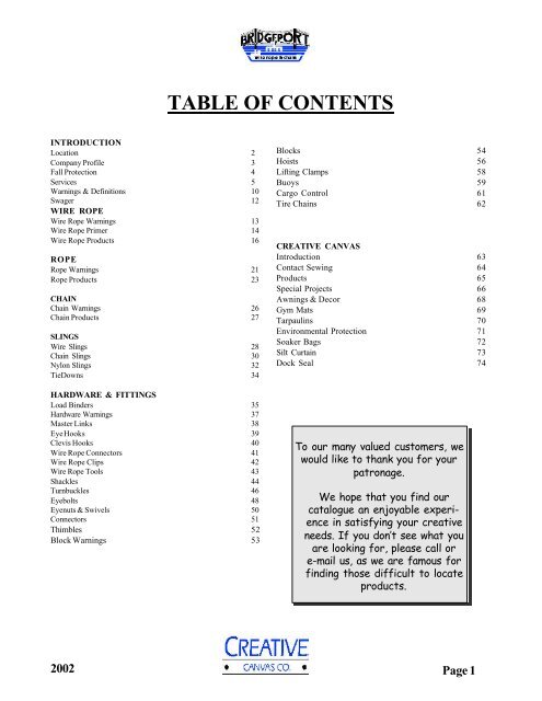
TABLE OF CONTENTS<br />
INTRODUCTION<br />
Location 2<br />
Company Profile 3<br />
Fall Protection 4<br />
Services 5<br />
Warnings & Definitions 10<br />
Swager 12<br />
WIRE ROPE<br />
Wire Rope Warnings 13<br />
Wire Rope Primer 14<br />
Wire Rope Products 16<br />
ROPE<br />
Rope Warnings 21<br />
Rope Products 23<br />
CHAIN<br />
Chain Warnings 26<br />
Chain Products 27<br />
SLINGS<br />
Wire Slings 28<br />
Chain Slings 30<br />
Nylon Slings 32<br />
TieDowns 34<br />
HARDWARE & FITTINGS<br />
Load Binders 35<br />
Hardware Warnings 37<br />
Master Links 38<br />
Eye Hooks 39<br />
Clevis Hooks 40<br />
Wire Rope Connectors 41<br />
Wire Rope Clips 42<br />
Wire Rope Tools 43<br />
Shackles 44<br />
Turnbuckles 46<br />
Eyebolts 48<br />
Eyenuts & Swivels 50<br />
Connectors 51<br />
Thimbles 52<br />
Block Warnings 53<br />
Blocks 54<br />
Hoists 56<br />
Lifting Clamps 58<br />
Buoys 59<br />
Cargo Control 61<br />
Tire Chains 62<br />
CREATIVE CANVAS<br />
Introduction 63<br />
Contact Sewing 64<br />
Products 65<br />
Special Projects 66<br />
Awnings & Decor 68<br />
Gym Mats 69<br />
Tarpaulins 70<br />
Environmental Protection 71<br />
Soaker Bags 72<br />
Silt Curtain 73<br />
Dock Seal 74<br />
To our many valued customers, we<br />
would like to thank you for your<br />
patronage.<br />
We hope that you find our<br />
<strong>catalogue</strong> an enjoyable experience<br />
in satisfying your creative<br />
needs. If you don’t see what you<br />
are looking for, please call or<br />
e-mail us, as we are famous for<br />
finding those difficult to locate<br />
products.<br />
2002 Page 1
LOCATIONS<br />
Branch Offices:<br />
1 Austin Street,<br />
St. John’s, Newfoundl<strong>and</strong>, Canada<br />
A1B 4C1<br />
Tel: (709)-579-7960 Fax: (709)-579-7964<br />
BRIDGEPORT WIRE ROPE & CHAIN LTD.<br />
CREATIVE CANVAS CO.<br />
70 Akerley Blvd.<br />
Dartmouth, Nova Scotia, Canada<br />
B3B 1R1<br />
Tel: (902)-468-0300 Fax: (902)-468-0303<br />
www.bridgeport<strong>wire</strong>.com<br />
www.creative-canvas.com<br />
520 Edinburgh Dr.<br />
Moncton, New Brunswick, Canada<br />
E1E 4C6<br />
Tel: (506)-382-7770 Fax: (506)-856-5131<br />
9 Dedication Street,<br />
Saint John, New Brunswick, Canada<br />
E2R 1A7<br />
Tel: (506)-696-3707 Fax: (506)-652-4505<br />
Page 2<br />
2002
COMPANY PROFILE<br />
<strong>Bridgeport</strong> Wire Rope & Chain is a 15-year old diversified Nova Scotia privately owned company. Our<br />
specialty is equipment <strong>and</strong> apparatus for lifting <strong>and</strong> securing applications. We supply <strong>wire</strong> <strong>rope</strong>, <strong>chain</strong>, <strong>rope</strong><br />
<strong>and</strong> related hardware to industrial, oil & gas, transportation, logging, mining <strong>and</strong> fishing sectors. Our textile<br />
division, Creative Canvas Co., manufactures related industrial <strong>and</strong> technical textile products, including<br />
tarpaulins, nylon web slings, geotextile products, awnings <strong>and</strong> custom sewn products, Creative Canvas has<br />
established itself as the finest custom sewing facility in Eastern Canada.<br />
We have a full rigging shop, complete with a proof load test bed. Our Evita certified <strong>wire</strong> <strong>rope</strong> inspectors<br />
serve both offshore <strong>and</strong> onshore industries for inspection of lifting <strong>wire</strong>, slings, <strong>and</strong> related hardware. Our<br />
Test Bed is approved by Lloyd’s register <strong>and</strong> DNV. Also, <strong>Bridgeport</strong> operations are registered to ISO 9002<br />
st<strong>and</strong>ards.<br />
Our head office & main warehouse is located in Dartmouth, Nova Scotia. We also have Branch offices in St.<br />
John’s, Newfoundl<strong>and</strong>, Moncton, New Brunswick, <strong>and</strong> Saint John, New Brunswick.<br />
TO PURSUE EXCELLENCE IN PRODUCTS, SERVICE AND<br />
PEOPLE<br />
IN ORDER TO<br />
MEET OR EXCEED OUR CUSTOMERS’ REQUIREMENTS<br />
Registered to:<br />
ISO 9002<br />
Test Facilities Approved by:<br />
Test Facilities Approved by:<br />
<strong>Bridgeport</strong> <strong>and</strong> its staff are proud to have earned certification<br />
<strong>and</strong> recognition from the leading st<strong>and</strong>ards groups in<br />
this sector. This commitment to consistent quality is maintained<br />
during all transactions with customers <strong>and</strong> suppliers.<br />
2002 Page 3
FALL PROTECTION EQUIPMENT<br />
INSPECTION/CERTIFICATION SERVICES<br />
<strong>Bridgeport</strong> Wire Rope & Chain is proud to introduce another new service. Our fall protection division<br />
offers products <strong>and</strong> services from North America’s leading manufactures of fall protection equipment.<br />
We specialize in custom inspection <strong>and</strong> certification services.<br />
Let our team of qualified, competent <strong>and</strong> trained professionals help develop <strong>and</strong> manage your fall<br />
protection equipment inventory.<br />
We offer state of the art tracking <strong>and</strong> inventory systems allowing for equipment traceability <strong>and</strong><br />
employee accountability of equipment.<br />
Our inspection services are available for individual site work or expedient service through our main<br />
inspection facility.<br />
Our inspection protocol procedure allows us to monitor <strong>and</strong> bench mark equipment used on a regular<br />
basis thus reducing the need for constant replacement of costly equipment.<br />
Our inspection protocol includes the following:<br />
√ Written inspection report for each piece of equipment.<br />
√ Evaluation on the piece of equipment.<br />
√ Posted record of the equipment reporting pass.<br />
√ Posted record of the equipment reporting failure.<br />
√ Yearly report for replacement of equipment<br />
√ Anniversay reminder for equipment inspections.<br />
√ Posted certificate 24/7.<br />
Did You Know?<br />
Inspection<br />
records must be<br />
maintained on<br />
fall protection<br />
equipement?<br />
Page 4<br />
2002
FALL PROTECTION COURSES DESIGNED TO MEET<br />
TODAY’S<br />
STRINGENT REQUIREMENTS FOR THE WORKPLACE<br />
Course 1: Basic Fall Arrest<br />
This course delivers an outline to cover the basic functions of fall<br />
arrest <strong>and</strong> fall prevention.<br />
This course will deal with basic fall arrest equipment <strong>and</strong> regulations.<br />
Company Specific training;<br />
Industry course;<br />
2 hrs., maximum 10 people<br />
2 hrs., maximum 10 people<br />
Course 2: Intermediate Fall Arrest<br />
This course delivers an in depth look at fall arrest <strong>and</strong> fall prevention<br />
in the workplace. This h<strong>and</strong>s on session will deal with day to day<br />
occurrences <strong>and</strong> fall arrest equipment.<br />
Company specific training;<br />
Industry course;<br />
2 hrs, maximum 10 people<br />
2 hrs, maximum 10 people<br />
Course 3: Advanced Fall Arrest<br />
This course delivers information on hazard assessment, equipment<br />
evaluation/inspection <strong>and</strong> competency.<br />
Company specific training;<br />
Industry course;<br />
4 hrs, 10 people<br />
4 hrs, 10 people<br />
Please note: All courses include testing <strong>and</strong> certificate upon completion.<br />
2002 Page 5
FALL PROTECTION / FALL ARREST<br />
TRAINING SERVICES<br />
Courses designed to meet today’s stringent requirements for fall protection in the workplace. Course<br />
content covers government regulations, industry st<strong>and</strong>ards, manufacturer practices <strong>and</strong> work place<br />
safety.<br />
We offer Company specific training designed to meet the actual needs of individual customers <strong>and</strong><br />
Industry training to individuals in the work place throughout Atlantic Canada.<br />
Company specific courses can be held on location or at our training facility in Dartmouth, Nova<br />
Scotia. This training is customized to deal with fall protection applications suited to your specific<br />
needs.<br />
Industry training will be held throughout Atlantic Canada <strong>and</strong> our Burnside Facility on a scheduled<br />
basis. This training deals with fall prevention protection in a wide variety of applications <strong>and</strong> situations.<br />
To inquire about course content, placement availability or course locations, please contact your local<br />
<strong>Bridgeport</strong> office or sales representative for more information.<br />
<strong>Bridgeport</strong> can also provide:<br />
Did You Know?<br />
√<br />
√<br />
√<br />
√<br />
Equipment inspections<br />
Certifications<br />
Designing <strong>and</strong> Installations Services<br />
Consulting Service<br />
Fall related accidents are<br />
the second highest reported<br />
accident in North America<br />
each year?<br />
P<strong>rope</strong>r training can reduce<br />
your chances of a fall.<br />
Let <strong>Bridgeport</strong> be your choice for sales, service <strong>and</strong> training in<br />
Atlantic Canada.<br />
Page 6<br />
2002
FALL PROTECTION PRODUCTS<br />
Full Body Harness<br />
Rope Lanyard<br />
Web Lanyard<br />
Shock Absorbing<br />
Lanyard<br />
Self Retracting Lifeline<br />
Description BWRC # Price<br />
Full Body Harness 83052 68.70<br />
Rope Lanyard 5/8 x 4'<br />
c/w snap hooks<br />
83024 66.50<br />
Rope Lanyard 5/8 x 4'<br />
c/w snap hook & rebar hook<br />
83023 125.50<br />
Web Laynard 1" x 6'<br />
c/w snap hooks<br />
83054 43.20<br />
Web Lanyard 1" x 6'<br />
Shock absorbing,<br />
83020 76.90<br />
c/w snap hooks<br />
Self retractable lifeline MFA-FL11-3<br />
c/w carabiner & swivel shackle<br />
276.00<br />
Self retractable lifeline<br />
MFA-FL11-6<br />
c/w rebar hook & swivel shackle<br />
310.00<br />
2002 Page 7
INSPECTION & TRAINING SERVICES<br />
<strong>Bridgeport</strong> Inspection <strong>and</strong> Training Inc. has been supplying both onshore <strong>and</strong> offshore services for the past 5 years.<br />
We are proud to offer a full range of services including the following:<br />
√<br />
√<br />
√<br />
√<br />
√<br />
Wire Rope <strong>and</strong> Lifting Gear Inspection<br />
Database Tracking of Certificates & Inspection reports<br />
Non Destructive Testing (Magnetic Particle Inspection <strong>and</strong> Load Testing)<br />
110,000 lb. Load Cell<br />
Power Lubrucation for Wire Rope<br />
We also have on staff certified inspection <strong>and</strong> repair personnel for:<br />
√<br />
√<br />
Chain Hoists<br />
DBI/Sala Fall Arrest Gear<br />
At present, our load test facilities are capable of load testing up to 350,000 lbs. <strong>Bridgeport</strong>’s test bed is both Lloyd’s <strong>and</strong><br />
DNV approved.<br />
Evita Training Services Ltd., located in the U.K., is recognized the world over for its knowledgeable <strong>and</strong> experienced<br />
staff. <strong>Bridgeport</strong> Wire Rope & Chain Ltd. has recently been named Evita Training’s North American Representative.<br />
Working with professional trainers, we can now offer Certification Courses in Wire Rope <strong>and</strong> Lifting Gear Inspections.<br />
Test Facilities Approved by:<br />
Test Facilities Approved by:<br />
350K, 350,000lb Testing Machine, 40’ Long<br />
Page 8<br />
2002
INSPECTION & TRAINING SERVICES<br />
<strong>Bridgeport</strong> Inpsection & Training offers courses designed to meet stringent offshore & onshore requirements<br />
for a safe workplace.<br />
Course 1: Crosby Lifting Gear<br />
This course is designed to familiarize participants in lifting gear applications <strong>and</strong><br />
applicable st<strong>and</strong>ards.<br />
Duration: 4 hours<br />
Course 2: Evita Wire Rope Examiner<br />
This course delivers an in depth look at p<strong>rope</strong>r use of Wire Rope on the job site, also<br />
enables the participants to identify degraded products not fit for use.<br />
This course is recognized in the Offshore Petroleum Industry.<br />
Duration: 2 Days<br />
Course 3: Evita Lifting Gear Examiner<br />
This course delivers an in depth look at p<strong>rope</strong>r use of Lifting Gear on the job site, also<br />
enables the participants to identify degraded products not fit for use.<br />
This course is recognized in the Offshore Petroleum Industry.<br />
Duration: 2 Days<br />
Course 4: <strong>Bridgeport</strong> Wire Rope & Lifting Gear<br />
This course is designed to familiarize participants in lifting gear applications <strong>and</strong><br />
applicable st<strong>and</strong>ards.<br />
Duration: 1 Day<br />
<strong>Bridgeport</strong> Instructors are certified by Evita <strong>and</strong> Crosby. The above courses are recognized by both<br />
PanCanadian <strong>and</strong> Sable Offshore.<br />
2002 Page 9
IMPORTANT WARNINGS <strong>and</strong> DEFINITIONS<br />
for use of this <strong>catalogue</strong><br />
Use all products p<strong>rope</strong>rly, in a safe manner <strong>and</strong> for the<br />
application for which they were intended. All products<br />
are sold with the express underst<strong>and</strong>ing that the purchaser<br />
is thoroughly familiar with their correct application <strong>and</strong><br />
safe use. The End-User is responsible for design <strong>and</strong> use<br />
decisions. <strong>Bridgeport</strong> Wire Rope & Chain Ltd. assumes no<br />
responsibility for the use or misapplication of any product<br />
sold by this company.<br />
Wear, corrosion, overloading, abuse, overuse, alterations<br />
<strong>and</strong> inadequate maintenance affect all products. These<br />
factors all contribute to product breakage. With lifting <strong>and</strong><br />
securing products, breaks can cause loads to fall or swing<br />
out of control. Major p<strong>rope</strong>rty damage, serious injury or<br />
death can result.<br />
To minimize that risk, follow four basic guidelines.<br />
1. Keep out from under a raised load, <strong>and</strong> away from the<br />
line of force.<br />
2. Underst<strong>and</strong> <strong>and</strong> observe Working Load Limit.<br />
3. Avoid shock loads.<br />
4. Match components p<strong>rope</strong>rly.<br />
5. Regularly inspect equipment <strong>and</strong> components.<br />
Maintain safe distances between the load force <strong>and</strong><br />
personnel.<br />
Keep out from under a raised load. Stay out of the line of<br />
force of a load. Never operate a load over people. Never<br />
ride on a load. While planning a lifting or securing project,<br />
the key consideration is that no equipment failure can<br />
result in personnel injury.<br />
Respect the Working Load Limit (W.L.L.) of all<br />
assemblies <strong>and</strong> components<br />
The WLL is the recommended maximum load to be applied<br />
to a product, at any time during its application cycle. It is<br />
based on a uniformly applied, straight-line load only, not<br />
side loading. WLL ratings are determined for typical<br />
environmental conditions. Application in temperature<br />
extremes or corrosive environments can reduce stated<br />
ratings. Under such conditions, or in higher-risk applications,<br />
a reduction to the stated working<br />
Apply forces gradually <strong>and</strong> uniformly.<br />
Avoid impacting, jerking or swinging of loads. A shock<br />
(sudden) load is generally significantly greater than the static<br />
load. The Working Load Limit could be exceeded <strong>and</strong><br />
component failure result. AVOID SHOCK LOADS.<br />
Carefully assess all assembly designs <strong>and</strong> component combinations.<br />
Get expert advice when in doubt.<br />
Components must match. Make certain that components<br />
such as hooks, links or shackles are used with <strong>wire</strong> <strong>rope</strong>,<br />
<strong>chain</strong> or cordage of suitable material size <strong>and</strong> strength for<br />
safe application. Attachments must be p<strong>rope</strong>rly installed,<br />
<strong>and</strong> must have a working load limit at least equal to the<br />
product with which they are being used. Remember: any<br />
device is only as strong as the weakest component.<br />
Inspect all equipment regularly, especially before each<br />
use.<br />
No product can keep operating at its rated capacity indefinitely.<br />
Inspect products regularly, preferably prior to each<br />
use. Carefully check each item for damage, wear, deformation,<br />
cracks or elongation – a sure sign of imminent failure.<br />
Immediately withdraw such items from service.<br />
The diversity of products <strong>and</strong> use involved makes blanket<br />
recommendations for inspection procedures <strong>and</strong> frequency<br />
impossible. Frequency of inspection will depend on environmental<br />
conditions, application, storage of product prior to<br />
use, frequency of use, etc. Best results are achieved when<br />
qualified personnel base their decision on information from<br />
rigging <strong>and</strong> engineering manuals <strong>and</strong> on experience from<br />
actual use in the field. Keep inspection records to help<br />
pinpoint problems <strong>and</strong> to ensure periodic inspection intervals<br />
Protect all products from corrosion. Rust damage is a real<br />
hazard. When in doubt about the extent of corrosion or<br />
other damage, withdraw the items from service.<br />
Destroy, rather than discard, items that have been<br />
judged defective . Someone not aware of the hazard<br />
involved might use them again.<br />
load limit should be applied. Any modifications to products<br />
will also change the working load limit.<br />
Page 10<br />
2002
DEFINITIONS<br />
Information in this <strong>catalogue</strong> is subject to change; all weights <strong>and</strong> dimensions are approximate. Ratings are stated in short<br />
tons (2000 pounds) or pounds. Unless otherwise stated, all dimensions are in Inches <strong>and</strong> all weights are in pounds.<br />
Working Load Limit<br />
The WLL is the recommended maximum load, which should ever be applied to a product during its use. It is also referred<br />
to as Safe Working Load (S.W.L.), Rated Capacity, Rated Load Value, <strong>and</strong> Resulting Safe Working Load. Whatever the<br />
terminology, a force exceeding a product’s performance rating must be avoided during all operations.<br />
See also Design Factor.<br />
Breaking Strength / Ultimate Strength<br />
NEVER use breaking strength as criterion for service or design purposes. Refer only to the WLL. Breaking Strengths,<br />
when published, were obtained under controlled laboratory conditions. A constantly increasing force is applied in direct<br />
line to the product at a uniform rate of speed on a st<strong>and</strong>ard pull-testing machine.<br />
Design Factor / Safety Factor<br />
An industry term defining the theoretical safety reserve of a product. It is usually computed by dividing the<br />
<strong>catalogue</strong> Breaking Strength by the <strong>catalogue</strong> WLL, generally expressed as a ratio.<br />
Proof Test Load<br />
“Proof Test” designates a controlled test applied to the product for the sole purpose of detecting defects in material or<br />
manufacture. The Proof Test Load (usually twice the WLL) is the load, which the product withstood without deformation<br />
when new, <strong>and</strong> under laboratory test conditions, similar to Breaking Strength procedures... The Proof Test results can<br />
never be considered as justification to exceed W.L.L.<br />
Shock Load<br />
A shock load results from a rapid change in movement, such as impacting, jerking or swinging a static load.<br />
Sudden release of tension also causes a shock load. Shock loads are generally significantly greater than static loads. Any<br />
shock loading must be considered when selecting the item for use in a system. Avoid shock loads. They can exceed the<br />
WLL.<br />
2002 Page 11
Introducing<br />
How To Design Your Assembly<br />
An exciting option that will grow to everyone’s<br />
benefit, especially the Automotive <strong>and</strong> Marine<br />
Sectors<br />
MANUAL BENCH SWAGER<br />
Swagers have led the <strong>wire</strong> <strong>rope</strong> fabrication industry<br />
for over 30 years. You can now enjoy the<br />
benefit of rapid rigging service. For large jobs our<br />
machine is portable, call us for on site service.<br />
We’ll make custom or special ends to meet your<br />
specifications, while you wait. We maintain a<br />
large inventory of fittings, <strong>and</strong> both bare <strong>and</strong><br />
coated cable for your immediate needs.<br />
Did You Know?<br />
That we can swage terminals<br />
on site?<br />
We can manufacture<br />
<strong>wire</strong> <strong>rope</strong> assemblies for<br />
gas line <strong>and</strong> brake cables<br />
while you wait ?<br />
Page 12<br />
2002
Wire Rope<br />
IMPORTANT WARNINGS<br />
The general warnings on Pages 10 apply to Wire Rope. Observe them!<br />
Wire Rope is a machine. Underst<strong>and</strong> <strong>and</strong> respect it.<br />
Like any machine, it needs p<strong>rope</strong>r care <strong>and</strong> maintenance for optimal safety <strong>and</strong> long service life. All users <strong>and</strong> operators<br />
must should be trained in using <strong>and</strong> operating <strong>wire</strong> <strong>rope</strong> systems, <strong>and</strong> follow all industry <strong>and</strong> regulatory st<strong>and</strong>ards for its<br />
applications.<br />
Rated Capacity<br />
Rated Capacity is the load, which a new <strong>wire</strong> <strong>rope</strong> may h<strong>and</strong>le under given operating conditions <strong>and</strong> at, assumed design<br />
factor. A design factor of 5 is chosen most frequently for <strong>wire</strong> <strong>rope</strong>. (i.e.: Operating Loads not to exceed 20% of<br />
<strong>catalogue</strong> Breaking Strength) Operating loads may have to be reduced when life, limb or valuable p<strong>rope</strong>rty is at risk or<br />
other than new <strong>rope</strong> is used. A design factor of 10 is preferred when <strong>wire</strong> <strong>rope</strong> is used to carry personnel. (Operating<br />
loads not to exceed 10% of <strong>catalogue</strong> Breaking Strength)<br />
Responsibility for choosing a design factor rests with the user.<br />
Attachments must have at least the same Working Load Limit as the <strong>wire</strong> <strong>rope</strong> used.<br />
Clips, sockets, thimbles, sleeves, hooks, links, shackles, sheaves, blocks, etc. must match in size, material <strong>and</strong> strength<br />
to provide adequate safety protection. P<strong>rope</strong>r installation is critical to obtain maximum safety <strong>and</strong> efficiency.<br />
Maintain safe distances <strong>and</strong> locations while operating <strong>wire</strong> <strong>rope</strong> systems.<br />
Do not operate a load over people. Do not ride on load. Keep out of the line of force during operations. Conduct all<br />
lifting operations in such a manner that if equipment were to fall or break, no personnel would be injured.<br />
Avoid Shock Loads<br />
Inspect <strong>wire</strong> <strong>rope</strong> regularly<br />
Check the general condition of the <strong>wire</strong> <strong>rope</strong>. Use professional inspection services, or obtain appropriate, specific<br />
training in inspections. Look for localized damage <strong>and</strong> wear, especially at <strong>wire</strong> <strong>rope</strong> attachments. Inspect all parts that<br />
come in contact with the <strong>wire</strong> <strong>rope</strong>. In addition to routine wear <strong>and</strong> abuse, poor performances of <strong>wire</strong> <strong>rope</strong> often results<br />
from worn or wrong-sized sheaves, drums, rollers, etc. Look for kinks, broken <strong>wire</strong>s, abrasions, lack of lubrication, rust<br />
damage, crushing, reduction of diameter, stretch or other obvious damage.<br />
If any of these conditions exists, or if there is any other possible damage to the <strong>wire</strong> <strong>rope</strong>, retire the <strong>wire</strong> <strong>rope</strong> When in<br />
doubt about potential damage, remove the <strong>rope</strong> from service immediately for further assessment. Without controlled<br />
testing <strong>and</strong>/or analysis, it is impossible to determine the strength of damaged or used <strong>wire</strong>. Therefore, any visible<br />
damage requires testing or discarding to maintain safety st<strong>and</strong>ards.<br />
Destroy, rather than discard, <strong>wire</strong> <strong>rope</strong> to be retired<br />
Someone not aware of the hazard might use <strong>wire</strong> <strong>rope</strong> that is not destroyed again. Destroy <strong>wire</strong> <strong>rope</strong> by cutting it into<br />
short pieces.<br />
2002 Page 13
WIRE ROPE PRIMER<br />
The construction <strong>and</strong> applications of <strong>wire</strong> <strong>rope</strong> is a diverse <strong>and</strong><br />
complex subject. With the wide range of industrial requirements<br />
for <strong>wire</strong> <strong>rope</strong>, there are a wide range of sizes <strong>and</strong> constructions<br />
manufactured for the market. A knowledgeable individual should<br />
select the <strong>wire</strong> <strong>rope</strong> for a specific application with experience in<br />
the specific requirements. This primer presents only a basic<br />
overview of <strong>wire</strong> <strong>rope</strong> terms <strong>and</strong> types, <strong>and</strong> how those factors<br />
reflect size <strong>and</strong> construction requirements for <strong>wire</strong> <strong>rope</strong>. <strong>Bridgeport</strong><br />
staff are trained <strong>and</strong> experienced in answering your inquiries<br />
on <strong>wire</strong> application, pricing <strong>and</strong> availability.<br />
CONSTRUCTION<br />
Wire <strong>rope</strong> is constructed by twisting individual <strong>wire</strong>s into str<strong>and</strong>s,<br />
<strong>and</strong> then twisting the str<strong>and</strong> bundles around a core to form the<br />
<strong>rope</strong>. The primary construction of the <strong>wire</strong> is described by<br />
number designation. The format is XX x YY, where XX is the<br />
number of bundles of str<strong>and</strong>s used in the <strong>wire</strong>, <strong>and</strong> YY is the<br />
number of <strong>wire</strong>s used to construct a str<strong>and</strong>. For example, a 6 x 26<br />
<strong>wire</strong> would have 6 str<strong>and</strong>s in its construction, each str<strong>and</strong><br />
comprised of 26 <strong>wire</strong>s.<br />
With <strong>wire</strong> <strong>rope</strong>s of equivalent diameter, a lower YY value<br />
indicates a larger <strong>wire</strong> was used in constructing the str<strong>and</strong>s. The<br />
<strong>wire</strong> <strong>rope</strong> will therefore have more resistant to abrasion, <strong>and</strong> also<br />
be stiffer. Conversely, a higher YY value means smaller <strong>wire</strong>s<br />
comprise the str<strong>and</strong>s. With more <strong>wire</strong>s used, they can move more<br />
independently. The result is a more flexible <strong>wire</strong>, but also less<br />
abrasion resistance.<br />
CORE<br />
Wire <strong>rope</strong> cores are the foundation center to <strong>rope</strong> construction. It<br />
supports the str<strong>and</strong>s <strong>and</strong> adds to the <strong>rope</strong>’s resilience. The core<br />
can be constructed of fiber or metal.<br />
Fibre core is usually identified as FC (fibre core) or PC (poly<br />
core) in the <strong>wire</strong>’s construction designation. Fibre core <strong>wire</strong> <strong>rope</strong>s<br />
are typically more supple <strong>and</strong> elastic, resulting in flexible <strong>wire</strong><br />
that is more resilient to shock loading.<br />
Metal core can be a solid str<strong>and</strong>, but is more often a<br />
str<strong>and</strong>ed core. This is identified as IWRC, independent<br />
<strong>wire</strong> <strong>rope</strong> core. A metal core increases a <strong>rope</strong>’s strength,<br />
<strong>and</strong> its durability. Because metal is less compressible<br />
than fibre, IWRC construction reduces crushing while<br />
running over sheaves, or being wound on drum. IWRC<br />
construction limits bridging as well. Bridging occurs<br />
when str<strong>and</strong>s <strong>and</strong> <strong>wire</strong>s, which move during operation,<br />
are compressed against each other. The resulting stress<br />
<strong>and</strong> fatigue cause the <strong>wire</strong> to break prematurely.<br />
CLASSIFICATIONS<br />
Although <strong>wire</strong> <strong>rope</strong> is described by its “str<strong>and</strong> x <strong>wire</strong>” count, <strong>wire</strong><br />
with different constructions can have similar p<strong>rope</strong>rties. This<br />
allows substitution amongst specific <strong>wire</strong> constructions with<br />
minimal change in efficiency <strong>and</strong> effectiveness. Although the<br />
classification categories are too diverse to detail in this primer, a<br />
few key classes are presented.<br />
6 x 7 This class includes <strong>rope</strong>s with 6 str<strong>and</strong>s, around<br />
fibre or steel core, with 6 or 7 <strong>wire</strong>s per str<strong>and</strong>. It is usually large<br />
<strong>wire</strong> with low flexibility, but high abrasion resistance. It is used in<br />
drilling, ski or tramway traction cables, <strong>and</strong> guy <strong>wire</strong>s.<br />
6 x 19 This class includes <strong>rope</strong>s with 6 str<strong>and</strong>s, around<br />
steel or fibre core, with 15 to 26 <strong>wire</strong>s per str<strong>and</strong>. This class has<br />
the greatest variety of industrial applications. It contains a wide<br />
range of combinations of abrasion resistance <strong>and</strong> flexibility.<br />
6 x 37 This class includes <strong>rope</strong>s with 6 str<strong>and</strong>s, around<br />
steel or fibre core, with 27 to 49 <strong>wire</strong>s per str<strong>and</strong>. They deliver<br />
maximum flexibility with reasonable resistance to crushing;<br />
suitable for high speed multiple revving applications<br />
17 x 7 & 18 x 7 This class covers non-rotating<br />
<strong>wire</strong>s, typically with 11 or 12 outer layer str<strong>and</strong>s laid right<br />
h<strong>and</strong>, over a layer of 6 inner str<strong>and</strong>s laid left h<strong>and</strong>, around<br />
a fibre or steel core. The non-rotating p<strong>rope</strong>rty is required<br />
when lifting an unguided load, which could spin, or where<br />
the spinning of the load could open the construction of<br />
conventional <strong>rope</strong>.<br />
Aircraft cable This class includes smaller<br />
diameter <strong>rope</strong>s with 7 str<strong>and</strong>s, with 7 or 19 <strong>wire</strong>s per<br />
str<strong>and</strong>. They are noted for high tensile strength, high<br />
fatigue resistance <strong>and</strong> minimal stretch. Despite their<br />
popular name, they are not intended for aircraft use.<br />
LAY<br />
The direction of twist in the str<strong>and</strong> <strong>and</strong> <strong>wire</strong> <strong>rope</strong> construction<br />
is referred to as the lay. The designation describes<br />
whether the str<strong>and</strong>s rotate to the right or left away from<br />
the observer, when viewed from above.<br />
Right <strong>and</strong> left lays are combined around the core <strong>and</strong> in<br />
successive layers in various combinations. How the lays<br />
are combined or alternated determines the <strong>wire</strong> <strong>rope</strong>’s<br />
application, including rotational p<strong>rope</strong>rties, resistance to<br />
kinking <strong>and</strong> twisting, splicing p<strong>rope</strong>rties, <strong>and</strong> durability.<br />
IWRC is also resistant to higher temperatures, which<br />
can damage fibre cores.<br />
Page 14<br />
2002
WIRE ROPE PRIMER<br />
MATERIALS<br />
Wire <strong>rope</strong>s have been manufactured using a wide range of grade<br />
of steel. Higher-grade steel gives equivalent size/construction<br />
<strong>rope</strong>s higher breaking strength. Today, most <strong>wire</strong> constructed<br />
from IPS (improved plow steel), EIPS (extra improved plow<br />
steel), or EEIPS (extra improved plow steel) BRIDGEPORT<br />
typically stocks EIPS grade <strong>wire</strong> <strong>rope</strong>.<br />
SURFACE FINISH<br />
Wire with an uncoated finish is referred to as Bright (BRT).<br />
Galvanized (GAL) <strong>wire</strong> has zinc coating on the surface, <strong>and</strong><br />
provides improved resistance to corrosion. Wire is also produced<br />
in Stainless Steel (SS), which provides superior corrosion<br />
resistance. For equivalent <strong>wire</strong> size <strong>and</strong> construction, Bright is<br />
the least expensive, Stainless the most expensive.<br />
Some <strong>wire</strong>s are drawn through a die after construction. They are<br />
referred to as swaged, compressed, die-formed, or proprietary<br />
terms for that process. This reduces the ridges that result from<br />
the <strong>wire</strong>/str<strong>and</strong> construction, making a flatter <strong>wire</strong>. This can<br />
improve <strong>wire</strong> contact with sheaves or other surfaces during<br />
specialized applications.<br />
Most <strong>wire</strong>s have a lubricant added during construction. This aids<br />
the movement of the <strong>wire</strong> components against each other, <strong>and</strong> aids<br />
in corrosion resistance. Typically a light lubricant, a heavier<br />
grease form can be used to effectively seal the <strong>wire</strong>. All lubricated<br />
<strong>wire</strong>s should be re-lubricated while in service as a maintenance<br />
program. Some specialized <strong>wire</strong>s are constructed with no<br />
lubricant to facilitate their field application.<br />
Wire <strong>rope</strong> is also produced with a vinyl/plastic covering. This can<br />
increase the overall diameter of the <strong>wire</strong> (i.e.: an exterior jacket),<br />
or fill the voids between the str<strong>and</strong>s <strong>and</strong> <strong>wire</strong>s. Depending on the<br />
coating material, size <strong>and</strong> application, the coating provides<br />
corrosion protection, excludes dirt penetrating the <strong>wire</strong> construction,<br />
<strong>and</strong> acts as a lubricant or bridging reducer<br />
.<br />
UNREELING/UNCOILING<br />
When unreeling or uncoiling <strong>wire</strong> <strong>rope</strong>, it is essential that the reel<br />
or coil can rotate. When unwound from a stationary reel or spool,<br />
<strong>wire</strong> <strong>rope</strong> will kink, ruining the <strong>rope</strong>’s p<strong>rope</strong>rties. Mount the reel<br />
on a movable horizontal or vertical spindle, <strong>and</strong> pull off the <strong>rope</strong>.<br />
Alternately, the <strong>rope</strong> end can be secured <strong>and</strong> the reel rolled to play<br />
off the <strong>rope</strong>. When coiled, the <strong>rope</strong> end must be secured <strong>and</strong> the<br />
coil rolled like a hoop to play off the <strong>rope</strong>.<br />
To transfer <strong>rope</strong> from one reel to another, the <strong>rope</strong> should travel<br />
from the top of one reel to the top of the take-up reel. Reeling<br />
from bottom to bottom of the reels is also acceptable, provided<br />
potential floor contact doesn’t put dirt or contamination on the<br />
<strong>wire</strong>.<br />
GAUGING WIRE ROPE SIZE<br />
Wire <strong>rope</strong> size is expressed as the <strong>rope</strong> diameter. It is best measured<br />
with a micrometer. Rotate the micrometer around the <strong>rope</strong> to<br />
ensure maximum diameter measurement. Otherwise, the smaller<br />
diameter between str<strong>and</strong> ridges could be measured. When measuring<br />
<strong>rope</strong> that has been in service, measure at numerous points along<br />
its length. This ensures measurements are not based on a flattened<br />
or elongated point caused by usage.<br />
HOW TO ORDER WIRE ROPE<br />
A <strong>wire</strong> <strong>rope</strong> order should minimally specify the required diameter,<br />
length, construction, <strong>and</strong> grade (i.e.: steel, surface finish, etc.) Be<br />
sure to include any specific instructions to facilitate your use of the<br />
<strong>wire</strong> <strong>rope</strong>. This could include preferences such as on reel or coil<br />
storage, or specialized fittings <strong>and</strong> their attachment points<br />
If you are uncertain about a specification, provide your <strong>Bridgeport</strong><br />
contact with details of your application <strong>and</strong> required results. Our<br />
objective is to ensure your receive the product that meets your<br />
needs.<br />
2002 Page 15
Diameter<br />
(in.)<br />
Construction<br />
Core<br />
WIRE ROPE<br />
Finish<br />
Working<br />
Load Limit<br />
(lb)<br />
BWRC<br />
Part #<br />
z 1x7 NA GAL. seizing NA 31126 0.14<br />
Price<br />
(ft)<br />
z 7x7 IWRC GAL. ACC 110 30180 0.05<br />
z 7x7 IWRC SS ACC 100 30190 0.11<br />
W 1x7 NA GAL. seizing NA 31125 0.15<br />
W 7x7 IWRC GAL. ACC 200 31115 0.08<br />
W 7x7 IWRC GAL. PVC coated to 3/16 200 31123 0.18<br />
W 7x7 IWRC GAL. PVC coated to 1/4 200 31124 0.49<br />
W 7x7 IWRC SS ACC 180 31118 0.18<br />
8 7x19 IWRC GAL. ACC 400 30380 0.13<br />
8 7x7 IWRC GAL. PVC coated to 3/16 320 30385 0.25<br />
8 7x19 IWRC GAL. nylon coated to 3/16 400 30395 0.79<br />
8 7x7 IWRC SS ACC 260 30390 0.25<br />
E 7x19 IWRC GAL. ACC 560 30653 0.17<br />
E 7x7 IWRC SS ACC 480 30654 0.38<br />
x 7x19 IWRC GAL. ACC 840 30410 0.15<br />
x 7x19 IWRC GAL. PVC coated to 1/4 840 30411 0.32<br />
x 7x19 IWRC GAL. nylon coated to 1/4 840 30415 0.98<br />
x 7x7 IWRC SS ACC 700 30409 0.64<br />
4 1x7 NA GAL. Guy Str<strong>and</strong> 1260 30348 0.27<br />
4 7x19 IWRC GAL. ACC 1330 30350 0.19<br />
4 7x19 IWRC GAL. PVC coated to 5/16 1330 30360 0.41<br />
4 7x19 IWRC SS ACC 1280 30375 0.92<br />
c 1x7 NA GAL. Guy Str<strong>and</strong> 2130 30649 0.30<br />
c 7x19 IWRC GAL. ACC 1960 30650 0.30<br />
c 7x19 IWRC GAL. PVC coated to 3/8 1960 30651 0.59<br />
c 7x19 IWRC SS ACC 1900 30652 1.47<br />
c 6x36 IWRC GAL. 1900 30902 0.74<br />
c 19x7 IWRC BRT N/R 1630 30648 1.05<br />
a 1x7 NA GAL. Guy Str<strong>and</strong> 3080 30595 0.48<br />
a 7x19 IWRC GAL. ACC 2880 30600 0.39<br />
a 7x19 IWRC GAL. PVC coated to 7/16 2880 30647 0.64<br />
a 7x19 IWRC SS ACC 2280 30645 1.89<br />
a 6x19 poly GAL. 2100 30570 0.54<br />
a 6x24 poly GAL. Clean 1625 30585 0.54<br />
a 6x26 IWRC BRT 3000 30620 0.77<br />
a 6x36 IWRC GAL. 3000 30644 0.98<br />
a 19x7 IWRC BRT N/R 2400 30538 1.11<br />
Did You Know?<br />
Keeping your<br />
<strong>wire</strong> p<strong>rope</strong>rly<br />
lubricated<br />
prolongs <strong>wire</strong><br />
life<br />
Page 16<br />
2002
Diameter<br />
(in.)<br />
WIRE ROPE<br />
Construction<br />
Core<br />
Finish<br />
Working<br />
Load Limit<br />
(lb)<br />
BWRC<br />
Part #<br />
v 6x19 poly GAL. 6,460 30808 0.64<br />
v 6x24 poly GAL. 2,600 30790 0.56<br />
v 6x26 IWRC BRT 4,140 30805 0.90<br />
v 6x36 IWRC GAL. 3.670 30809 1.25<br />
v 19x7 IWRC BRT N/R 3,300 30788 1.16<br />
Price<br />
(ft)<br />
2 6x19 poly GAL. 3,660 30230 0.70<br />
2 6x24 poly GAL. Clean 3,360 30250 0.55<br />
2 6x26 IWRC BRT 5,000 30320 1.01<br />
2 6x26 IWRC GAL. 4,500 30322 1.15<br />
2 6x26 IWRC SS 4,300 30324 4.90<br />
2 6x26 IWRC Swaged 6,000 30321 1.40<br />
2 6x36 IWRC BRT 5,000 30340 1.73<br />
2 6x36 IWRC GAL. 4,500 30343 2.06<br />
2 6x37 poly GAL. 3,600 30275 1.06<br />
2 19x7 IWRC BRT N/R 4,300 30215 1.39<br />
12 6x26 IWRC SuperSwaged 7,000 30325 1.61<br />
b 6x19 poly GAL. 5,100 30930 1.02<br />
b 6x24 poly GAL. Clean 4,100 30960 0.59<br />
b 6x26 IWRC BRT 6,500 30965 1.18<br />
b 6x26 IWRC Swaged 8,000 30967 1.44<br />
b 6x36 IWRC GAL. 6,040 30962 1.55<br />
b 18x7 poly GAL. 30925 1.86<br />
b 19x7 IWRC BRT N/R 5,400 30926 1.75<br />
s 6x15 poly Lashing NA 30426 0.63<br />
s 6x19 poly GAL. 7,600 30693 1.18<br />
s 6x21 poly Drill Line 6.680 30695 1.32<br />
s 6x24 poly GAL. Clean 5,400 30720 1.07<br />
s 6x26 IWRC BRT 8.000 30760 1.18<br />
s 6x26 IWRC GAL. 7.400 30762 1.57<br />
s 6x26 IWRC Swaged 10,000 30761 1.47<br />
s 6x36 IWRC BRT 8,000 30780 1.57<br />
s 6x36 IWRC GAL. 7,400 30774 1.61<br />
s 6x37 poly GAL. 5,700 30778 1.60<br />
s 19x7 IWRC BRT N/R 6,700 30674 1.89<br />
s 18x7 poly GAL. N/R 6,040 30672 1.92<br />
2002 Page 17
Diameter<br />
(in.)<br />
Construction<br />
Core<br />
WIRE ROPE<br />
Finish<br />
Working<br />
Load Limit<br />
(lb)<br />
BWRC<br />
Part #<br />
Price<br />
(ft)<br />
w 6x15 NA Lashing NA 30428 0.81<br />
w 6x19 poly GAL. 12,200 30429 1.71<br />
w 6x21 poly LH Drill Line 9,000 30433 1.68<br />
w 6X24 poly GAL. Clean 7,400 30475 1.38<br />
w 6x26 IWRC BRT 12,000 30520 1.72<br />
w 6X26 IWRC GAL. 10,600 30528 2.06<br />
w 6x26 IWRC Swaged 14,000 30460 2.75<br />
w 6x36 IWRC BRT 12,000 30533 2.06<br />
w 6x37 poly GAL. Clean 9,000 30535 1.92<br />
d 4x7 poly GAL. 14,600 30810 1.86<br />
d 6x19 poly GAL. 11,600 30856 2.31<br />
d 6x24 poly GAL. Clean 16,000 30860 1.76<br />
d 6x26 IWRC BRT 14,500 30890 2.44<br />
d 6x26 IWRC GAL. 14,500 30893 2.79<br />
d 6x36 IWRC BRT 16,000 30896 2.80<br />
d 6x36 IWRC GAL. 14,500 30895 3.18<br />
d 7 Flex IWRC MacWhyte 14,900 30892 5.20<br />
d 19x7 IWRC BRT N/R 13,000 30815 3.15<br />
1! 6x19 poly GAL. 21,000 30110 2.67<br />
1! 6x24 poly GAL. Clean 12,500 30125 2.34<br />
1! 6x26 IWRC BRT 20,000 30160 2.79<br />
1! 6x26 IWRC GAL. 18,600 30165 3.39<br />
1! 6x36 IWRC BRT 20,000 30171 2.97<br />
1! 6x36 IWRC GAL. 18,600 30174 3.36<br />
1! 6x37 poly GAL. Clean 16,000 30172 3.24<br />
1! 7 Flex IWRC MacWhyte 19,400 30202 4.95<br />
1! 19x7 IWRC BRT N/R 16,800 30106 4.13<br />
!8 6x19 poly GAL. 24,000 30060 3.20<br />
!8 6x24 poly GAL. Clean 16,400 30075 3.38<br />
!8 6x26 IWRC BRT 25,000 30100 3.70<br />
!8 6x26 IWRC GAL. 22,200 30101 3.77<br />
!8 6x36 IWRC GAL. 22,200 30103 4.41<br />
!8 19x7 IWRC BRT N/R 21,000 30104 4.89<br />
Page 18<br />
2002
WIRE ROPE<br />
Diameter<br />
(in.)<br />
Construction Core Finish<br />
Working<br />
Load Limit<br />
(lb)<br />
BWRC<br />
Part #<br />
Price<br />
(ft)<br />
!4 6x26 IWRC BRT 30,000 30045 4.40<br />
!4 6X36 IWRC BRT 30,000 30038 4.50<br />
!4 6X36 IWRC GAL. 27,000 30058 4.55<br />
!2 6x26 IWRC BRT 44,000 30005 6.25<br />
!2 6x36 IWRC GAL. 39,100 30015 6.72<br />
!w 6x36 IWRC GAL. 52,000 30020 9.45<br />
@ 6x36 IWRC GAL. 67,600 30030 14.00<br />
@411 6x36 IWRC GAL. 84,600 30044 17.80<br />
@2 6X36 IWRC GAL. 102,600 30050 22.50<br />
GALV. AIRCRAFT CABLE<br />
PRE CUT REELS<br />
Diameter<br />
(in.)<br />
Construction<br />
Core Finish<br />
Length<br />
(ft)<br />
BWRC<br />
Part #<br />
Price<br />
per reel<br />
z 7x19 IWRC Gal ACC 500 31005 20.52<br />
8 7x19 IWRC Gal ACC 500 31010 35.53<br />
x 7x19 IWRC Gal ACC 500 31014 77.00<br />
4 7x19 IWRC Gal ACC 500 31018 97.86<br />
c 7x19 IWRC Gal ACC 500 31022 159.40<br />
a 7x19 IWRC Gal ACC 500 31026 201.08<br />
z 7x19 IWRC Gal ACC 1000 31008 38.58<br />
8 7x19 IWRC Gal ACC 1000 31012 61.60<br />
x 7x19 IWRC Gal ACC 1000 31016 147.00<br />
4 7x19 IWRC Gal ACC 1000 31020 189.00<br />
c 7x19 IWRC Gal ACC 1000 31024 298.40<br />
a 7x19 IWRC Gal ACC 1000 31028 390.60<br />
2002 Page 19
METRIC WIRE<br />
Diameter<br />
(mm)<br />
Construction<br />
Construction<br />
Core<br />
Finish<br />
Working<br />
Load Limit<br />
(lb)<br />
BWRC<br />
Part #<br />
Price<br />
(ft)<br />
9 8x19 IWRC BRT 2220 30934 1.21<br />
11 8x19 IWRC BRT 3315 30383 1.71<br />
13 8x36 IWRC BRT 4520 30387 1.81<br />
14 8x36 IWRC BRT 5258 30389 1.87<br />
16 8x36 IWRC BRT 6864 30391 2.19<br />
19 8x36 IWRC BRT 9680 30981 2.97<br />
Diameter<br />
(in.)<br />
TRAWL WARP<br />
<strong>Bridgeport</strong>’s TRIPLE ‘SSS’ trawl warp delivers longer life than regular 6x19 trawl <strong>wire</strong>. Your<br />
material <strong>and</strong> labor costs are reduced. With 3.5% larger diameter outside <strong>wire</strong>s, TRIPLE ‘SSS’<br />
delivers greater abrasion resistance <strong>and</strong> greater overall strength. See that strength gain below.<br />
The high-grade steel controlled heating <strong>and</strong> lead patenting of TRIPLE ‘SSS’ delivers that extra<br />
strength without sacrificing flexibility.<br />
TRIPLE ‘SSS’ is available in <strong>rope</strong> diameters of ½” to 1-1/8”. Look for the distinctive Double<br />
Red Str<strong>and</strong>.<br />
Core<br />
Finish<br />
Regular<br />
Trawl Wire<br />
Breaking<br />
Strength<br />
(lb.)<br />
Triple "SSS"<br />
Trawl Wire<br />
Breaking<br />
Strength<br />
(lb)<br />
BWRC<br />
Part #<br />
Price<br />
(ft)<br />
a 6x19 poly GAL. 10,500 11,300 30570 0.54<br />
v 6x19 poly GAL. 14,900 16,250 30806 0.68<br />
2 6x19 poly GAL. 18,300 26,700 30229 0.86<br />
b 6x19 poly GAL. 21,200 34,000 30931 1.10<br />
s 6x19 poly GAL. 30,000 40,000 30692 1.20<br />
w 6x19 poly GAL. 42,100 57,000 30430 1.78<br />
d 6x19 poly GAL. 56,500 78,300 30856 2.31<br />
, 6x19 poly GAL. 67,200 88,400 30975 2.40<br />
! 6x19 poly GAL. 78,800 100,600 30110 2.67<br />
!8 6x19 poly GAL. 91,400 126,500 30059 3.37<br />
Page 20<br />
2002
ROPE<br />
PRODUCT WARNINGS<br />
The general warnings on Pages 10 apply to Wire Rope.<br />
Observe them!!<br />
NEVER EXCEED WORKING LOAD LIMIT OF<br />
ROPE<br />
Use published WLL as guidelines only. WLL should be<br />
reduced when life, limb or valuable p<strong>rope</strong>rty is at risk, or<br />
other than new <strong>rope</strong> is used. When using multiple leg <strong>rope</strong><br />
slings, the WLL of each leg will have to be reduced<br />
considerably. Consult industry recommendations for<br />
information such as those published by the Cordage<br />
Institute. WLL will not apply if <strong>rope</strong> has been subjected to<br />
severe dynamic loading, which may not leave visible signs.<br />
AVOID OVERHEATING<br />
Exposure to high temperatures will cause <strong>rope</strong> to lose<br />
strength rapidly. Even temperatures as low as 150 degrees<br />
Fahrenheit (66 degrees Celsius) can reduce the strength of<br />
some <strong>rope</strong>s by 50%. When using synthetic <strong>rope</strong> (especially<br />
polypropylene) on a capstan or a winch, be careful to avoid<br />
excessive friction, which heats melts <strong>and</strong> fuses the outer<br />
fibers of the <strong>rope</strong>. Avoid repeated surging or hard rendering<br />
around poles or over cross arms. Polyester <strong>rope</strong> resists<br />
overheating best due to its high melting point.<br />
ATTACHMENTS MUST HAVE AT LEAST THE<br />
SAME WORKING LOAD LIMIT AS THE ROPE<br />
USED.<br />
Hooks, links, shackles, etc. must be of suitable material<br />
<strong>and</strong> strength to provide adequate safety protection. Splice<br />
<strong>rope</strong>s p<strong>rope</strong>rly <strong>and</strong> use thimbles if applicable. Choose <strong>rope</strong><br />
to match gear or gear to match <strong>rope</strong>. Sheaves, pulleys,<br />
thimbles, etc. that do not match the <strong>rope</strong> size used can<br />
cause dangerous friction, abrasion, or overload.<br />
MAINTAIN SAFE DISTANCES AND LOCATIONS<br />
WHILE USING ROPE.<br />
Do not operate a load over people. Do not ride on load.<br />
Conduct all lifting <strong>and</strong> securing operations in such a<br />
manner that if equipment were to fall or break, no personnel<br />
would be injured. NEVER STAND IN THE LINE OF<br />
ROPE UNDER STRAIN. If the <strong>rope</strong> breaks it will recoil<br />
with considerable force, especially if it is nylon.<br />
REMOVE ROPE FROM COILS AND REELS PROP-<br />
ERLY. Regular right h<strong>and</strong> laid <strong>rope</strong> should be uncoiled in a<br />
counter clockwise direction.<br />
Coiled Rope: Lay the coil on the floor with the inside end at<br />
bottom, then reach down through the center <strong>and</strong> pull the<br />
inside up through the coil.<br />
Reeled Rope: Remove the <strong>rope</strong> from a reel by pulling it off<br />
the top while the reel is free to rotate. Rope should never be<br />
taken from a reel lying on its end because it is more likely to<br />
kink or hockle or pull yarns on the wooden flange.<br />
AVOID SHOCK LOADS.<br />
Rope that is strong enough to withst<strong>and</strong> a steady pull can be<br />
broken with a sudden jerk. Be aware of all possible dynamic-loading<br />
situations. Avoid them, or use stronger <strong>rope</strong><br />
when they cannot be avoided. The effects of dynamic<br />
loading are greater on shorter <strong>rope</strong>s than on longer <strong>rope</strong>s,<br />
<strong>and</strong> greater on low elongation <strong>rope</strong>s (Manila <strong>and</strong> polypropylene)<br />
than on high elongation <strong>rope</strong>s (nylon).<br />
INSPECT ROPE FREQUENTLY.<br />
Closely examine the entire length of <strong>rope</strong> to determine<br />
general condition <strong>and</strong> detect localized wear. Excessive<br />
abrasion, fusing of outside fibers, hockles, rust or other<br />
chemical stains, broken fibers or other obvious damage are<br />
reasons to retire <strong>rope</strong> from service. Twisting str<strong>and</strong>s open<br />
<strong>and</strong> checking for powdered fiber can assess internal damage.<br />
Rope that is suspect of having been exposed to severe shock<br />
loads, or loads close to its catalog breaking strength, should<br />
be retired immediately. Such damage may not be visible.<br />
Actual remaining strength of damaged or used <strong>rope</strong> can only<br />
be established by laboratory analysis <strong>and</strong> tension tests.<br />
DESTROY, RATHER THAN DISCARD, ROPE TO BE<br />
RETIRED.<br />
Someone not aware of the hazard or defect might use it<br />
again. This is best achieved by cutting it up into short<br />
pieces.<br />
2002 Page 21
PROPER CARE OF ROPE<br />
Avoid abrasion <strong>and</strong> unnecessary wear. Outer fibers as<br />
well as inner fibers contribute to a <strong>rope</strong>’s strength. When<br />
outer fibers are worn by chafing or dragging over splintered,<br />
rough or gritty surfaces, the <strong>rope</strong> is worn <strong>and</strong><br />
weakened. When <strong>rope</strong> is used on cleats, winchheads etc.<br />
make sure they are smooth <strong>and</strong> use chafing gear when<br />
possible. Prevent unraveling of <strong>rope</strong> - whip or tape cut<br />
ends.<br />
Avoid sharp angles <strong>and</strong> bends . Sharp angles greatly<br />
affect the strength of a <strong>rope</strong>. Any sharp angle or bend is a<br />
weak spot. Use thimbles or chafing gear or padding<br />
where possible. Knots are also weak spots. They can<br />
reduce strength by as much as 50% or more. Use splices<br />
instead.<br />
Splice <strong>rope</strong> correctly. When a small section of a <strong>rope</strong> has<br />
been worn or damaged, cut out the section <strong>and</strong> splice it<br />
together. Splice in extra tucks for synthetic fiber <strong>rope</strong>s.<br />
Use p<strong>rope</strong>r splicing procedures as outlined by the Cordage<br />
Institute. Do not re-splice <strong>rope</strong> that broke due to being<br />
overloaded - discard it. Its remaining strength will only be<br />
a fraction of the WLL when new.<br />
Avoid sustained loads . Fiber <strong>rope</strong>s subjected to heavy<br />
loads for long periods of time can break well below<br />
catalog Breaking Strength. Natural fiber <strong>rope</strong>s such as<br />
Manila <strong>and</strong> Sisal have less ability to take sustained loads<br />
than synthetic fiber <strong>rope</strong>s such as nylon <strong>and</strong> polypropylene.<br />
Never exceed the WLL <strong>and</strong> do not subject fiber <strong>rope</strong><br />
to sustained loads for more than two days.<br />
Avoid rust. All <strong>rope</strong>s, synthetic or natural, should be kept<br />
away from rusting iron or steel. Rust can cause rapid loss<br />
of strength, sometimes in as short a time as one to two<br />
weeks. If <strong>rope</strong>s become rust stained, inspect the extent of<br />
the stain. If it is halfway through the <strong>rope</strong>, the <strong>rope</strong>’s<br />
capacity may be reduced by as much as 50%.<br />
Keep <strong>rope</strong> away from chemicals. Even though synthetic<br />
<strong>rope</strong> is generally considered to be resistant to damage<br />
from oils, gasoline, paint <strong>and</strong> most chemicals, exposure to<br />
any of these may cause some damage. Avoid contact with<br />
such things as storage battery solution, washing compounds<br />
or solutions, <strong>and</strong> animal wastes. Strong acids,<br />
alkalis <strong>and</strong> solvents can damage any <strong>rope</strong>. Natural fiber<br />
<strong>rope</strong> is extremely vulnerable to all chemicals <strong>and</strong> solvents.<br />
Avoid the use of swivels in <strong>rope</strong>s under load. A loss of<br />
turn will cause permanent damage to the <strong>rope</strong>.<br />
combination with a <strong>rope</strong> of lower stretch. The nylon line<br />
will stretch <strong>and</strong> not carry its proportionate share of the load,<br />
thus putting extra strain on the other lines.<br />
Reverse ends of the <strong>rope</strong> periodically. Especially in<br />
tackles <strong>and</strong> winches, reverse the <strong>rope</strong> end-for-end periodically<br />
so that all sections will be worn equally. Also, using a<br />
line in one direction over a winch many times can also<br />
damage the <strong>rope</strong> by twisting it too tight, or untwisting it so<br />
that hockles occur. Kinks pulled through a restricted space,<br />
such as a tackle block, can seriously damage <strong>rope</strong> fibers.<br />
The initial use should be in a clockwise direction, then<br />
reverse the <strong>rope</strong> periodically.<br />
Slack off guys in wet weather. When <strong>rope</strong>s are used as<br />
guy lines or other supports exposed to weather, they should<br />
be slacked off in wet weather, or damage to the <strong>rope</strong>, as well<br />
as what is being supported, may result.<br />
Store <strong>rope</strong> p<strong>rope</strong>rly. Rope is best stored in a dry, unheated<br />
place where air circulates freely, off the floor, <strong>and</strong> away from<br />
direct sunlight <strong>and</strong> other contact with the elements. Keep in<br />
mind that synthetic <strong>rope</strong>s will deteriorate in direct sunlight<br />
due to exposure to ultraviolet radiation. Light colored<br />
polypropylene especially is severely affected, smaller<br />
diameters more so than larger ones. Natural fiber <strong>rope</strong>s<br />
(Manila <strong>and</strong> Sisal) will deteriorate in storage even under<br />
ideal conditions.<br />
Dry <strong>rope</strong> p<strong>rope</strong>rly. Whenever natural fiber <strong>rope</strong>s become<br />
wet they should always be thoroughly dried before they are<br />
stored or they will rot in a very short time. Do NOT dry<br />
synthetic fiber <strong>rope</strong> in direct sunlight.<br />
Keep <strong>rope</strong> clean. Dirt on the surface of <strong>rope</strong> can become<br />
embedded inside <strong>and</strong> act as an abrasive on fibers. When<br />
<strong>rope</strong> gets dirty, wash it thoroughly with clean fresh water.<br />
Remember to dry natural fiber <strong>rope</strong> before storing.<br />
When substituting natural fiber <strong>rope</strong> with synthetic fiber<br />
<strong>rope</strong>s (or synthetic for synthetic) substitution should not be<br />
made on a straight breaking strength-for-breaking strength<br />
basis only. Other important factors must be considered.<br />
Page 22<br />
2002
POLYPROPYLENE<br />
ROPE<br />
<strong>Bridgeport</strong> carries a full line of SuperDan 3-st<strong>and</strong> polypropylene <strong>rope</strong>. SuperDan delivers advanced durability,<br />
with excellent anti-abrasion p<strong>rope</strong>rties <strong>and</strong> prolonged lifetime (over 105% that of regular poly). It also<br />
delivers superior strength, typically up to 50% greater than B.S. <strong>and</strong> ISO ratings. A proven multi-purpose<br />
<strong>rope</strong>, it has excellent application in the fishing sector, especially for deep-water traps.<br />
Diameter<br />
(in.)<br />
Quantity<br />
(ft.)<br />
Breaking<br />
Strength<br />
(lb)<br />
Superdan<br />
Colour<br />
BWRC<br />
Part #<br />
Price<br />
($/lb.)<br />
4 1,200 1670 Green 20795 2.17<br />
4 1,200 1670 Yellow 20797 2.17<br />
T 1,200 2560 Green 20807 2.17<br />
T 1,200 2560 Yellow 20860 2.17<br />
c 1,200 3170 Green 20800 2.17<br />
c 1,200 3170 Yellow 20799 2.17<br />
a 1,200 3920 Green 20802 2.17<br />
a 1,200 3920 Yellow 20803 2.17<br />
v 1,200 4870 Green 20813 2.17<br />
v 1,200 4870 Yellow 20862 2.17<br />
2 600 6870 Green 20804 2.17<br />
2 600 6870 Yellow 20866 2.17<br />
2 1,200 6870 Green 20805 2.17<br />
2 1,200 6870 Yellow 20864 2.17<br />
b 1,200 9320 Green 20806 2.17<br />
b 1,200 9320 Yellow 20824 2.17<br />
s 600 11500 Green 20808 2.17<br />
s 600 11500 Yellow 20870 2.17<br />
s 1,200 11500 Green 20809 2.17<br />
s 1,200 11500 Yellow 20868 2.17<br />
w 600 14600 Green 20810 2.17<br />
w 600 14600 Yellow 20872 2.17<br />
w 1,200 14600 Green 20811 2.17<br />
d 600 21100 Green 20812 2.17<br />
d 1,200 21100 Green 20801 2.17<br />
! 600 24300 Green 20814 2.17<br />
!8 600 31600 Green 20816 2.17<br />
!4 600 34600 Green 20818 2.17<br />
!2 600 48500 Green 20820 2.17<br />
!s 600 58500 Green 20822 2.17<br />
@ 600 87800 Green 20825 2.17<br />
2002 Page 23
ROPE<br />
Polypropylene 8 Str<strong>and</strong> (Plated) Super Dan<br />
Circumference<br />
(in.)<br />
Polypropylene 3 Str<strong>and</strong> (Yellow)<br />
Industrial Reels<br />
Diameter<br />
(in.)<br />
Quantity<br />
(ft.)<br />
Breaking<br />
Strength<br />
(lb.)<br />
BWRC<br />
Part #<br />
Price per<br />
Coil<br />
x 2125 720 21060 34.50<br />
4 1310 1050 21055 34.50<br />
c 975 1700 21065 34.50<br />
a 630 2450 21070 34.50<br />
2 335 3600 20989 34.50<br />
s 200 5500 21075 34.50<br />
w 125 8000 21080 34.50<br />
Circumference<br />
(in.)<br />
Diameter<br />
( in.)<br />
Diameter<br />
( in.)<br />
Quantity<br />
(ft.)<br />
Quantity<br />
(ft.)<br />
Average<br />
Breaking<br />
Strength<br />
(lb.)<br />
Polypropylene 8 Str<strong>and</strong> (Plated) Danline<br />
Average<br />
Breaking<br />
Strength<br />
(lb.)<br />
BWRC<br />
Part #<br />
BWRC<br />
Part #<br />
Price<br />
($/lb.)<br />
Price<br />
($/lb.)<br />
Weight per<br />
coil<br />
(lb)<br />
5 ! s" 720 62500 21897 2.35 382<br />
6 @ 720 91400 21902 2.35 577<br />
7 @ 4 720 120600 21912 2.35 781<br />
8 @ s 720 155000 21922 2.35 1016<br />
9 # 720 197100 21932 2.35 1282<br />
10 # 4 720 238600 21927 2.35 1584<br />
Weight per<br />
coil<br />
(lb)<br />
5 ! s" 720 36,000 21895 2.35 342<br />
6 @ 720 52,000 21900 2.35 497<br />
7 @ 4 720 69,000 21910 2.35 663<br />
8 @ s 720 90,000 21920 2.35 864<br />
9 # 720 114,000 21930 2.35 1102<br />
10 # 4 720 137,000 21925 2.35 1368<br />
Did you Know?<br />
Tying knots in<br />
<strong>rope</strong> reduces<br />
strength by up<br />
to 50%<br />
Diameter<br />
(in.)<br />
Quantity<br />
(ft.)<br />
Breaking<br />
Strength<br />
(lb.)<br />
BWRC<br />
Part #<br />
Price<br />
($/lb.)<br />
Weight per<br />
Coil<br />
(lbs)<br />
4 1,200 1650 20520 6.77 18<br />
c 1,200 2550 20568 6.77 30<br />
a 1,200 3700 20540 6.77 42<br />
2 600 6400 20510 6.77 39<br />
Cs 600 10400 20560 6.77 63<br />
w 600 14200 20530 6.77 87<br />
! 600 25000 20495 6.77 156<br />
Page 24<br />
2002
Sash Cord<br />
Type<br />
Diameter<br />
(in.)<br />
Quantity<br />
(ft.)<br />
BWRC<br />
Part #<br />
Price<br />
(ea.)<br />
#5 8 1,000 22115 96.60<br />
#6 x 100 22117 11.62<br />
#6 x 760 22116 96.60<br />
#7 R 100 22118 13.93<br />
#7 R 660 22119 96.60<br />
#8 4 100 22140 15.81<br />
#8 4 500 22150 96.60<br />
#10 c 100 22120 24.35<br />
#10 c 350 22125 96.60<br />
#12 a 100 22130 37.03<br />
#12 a 240 22135 96.60<br />
#16 2 170 22155 96.60<br />
ROPE<br />
Tarred Marlin<br />
Quantity<br />
(lb.)<br />
BWRC<br />
Part #<br />
Price<br />
($/lb.)<br />
Price per<br />
Coil<br />
(approx.)<br />
1 00910 7.40 7.40<br />
5 00905 7.10 35.50<br />
Barbour Twine<br />
Quantity<br />
(g.)<br />
BWRC<br />
Part #<br />
Price<br />
Spool<br />
250 00300 31.95<br />
Aluminum Fids<br />
Rope Size<br />
(in.)<br />
BWRC<br />
Part #<br />
Price<br />
(ea.)<br />
4 80710 8.37<br />
a 80720 9.77<br />
2 80705 11.17<br />
s 80725 13.99<br />
w 80715 16.77<br />
d 80730 20.99<br />
! 80700 26.54<br />
Wood Fids<br />
Length<br />
(in..)<br />
BWRC<br />
Part #<br />
Price<br />
(ea.)<br />
6 80742 8.79<br />
8 80745 9.73<br />
10 80750 12.03<br />
12 80755 12.95<br />
14 80760 14.55<br />
16 80765 20.93<br />
18 80770 30.51<br />
20 80772 36.39<br />
24 80774 51.64<br />
SPLICING TOOLS<br />
Pushers<br />
Length<br />
(in.)<br />
BWRC<br />
Part #<br />
Price<br />
!!211 81250 5.59<br />
!& 81245 9.37<br />
Sail Needles<br />
Type<br />
Length<br />
(in.)<br />
BWRC<br />
Part #<br />
Price<br />
#16 @a 81174 1.40<br />
#15 @2 81172 1.40<br />
#14 @w 81171 1.40<br />
#13 #8 81169 1.40<br />
#12 #a 81168 1.40<br />
#11 #2 81173 1.75<br />
#10 #w 81167 1.80<br />
#8 $s 81166 1.59<br />
Sail Palm<br />
Style<br />
BWRC<br />
Part #<br />
Price<br />
Right H<strong>and</strong> 81317 17.29<br />
Left H<strong>and</strong> 81318 17.29<br />
2002 Page 25
CHAIN<br />
IMPORTANT WARNINGS<br />
The general warnings on Pages 10 apply to Chain. Observe them!!<br />
Use only alloy <strong>chain</strong> for overhead lifting<br />
Grade 80 <strong>and</strong> Grade 100 alloy <strong>chain</strong> is the ONLY type of <strong>chain</strong> that can be used for<br />
overhead lifting.<br />
Never exceed the Working Load Limit of the <strong>chain</strong>.<br />
The Working Load Limit is the maximum load that to be applied to the <strong>chain</strong>, even when<br />
new <strong>and</strong> load is uniformly applied. WLL applies only to straight line pulls. When using<br />
multiple leg <strong>chain</strong> slings, the WLL of each leg will be reduced considerably depending<br />
on the angle of the sling legs.<br />
Attachments must have at least the same Working Load Limit as the <strong>chain</strong> used.<br />
Hooks, links, shackles, etc. must be of suitable material <strong>and</strong> strength to provide adequate<br />
safety protection.<br />
Maintain safe distances <strong>and</strong> locations while operating <strong>wire</strong> <strong>rope</strong> systems.<br />
Do not operate a load over people. Do not ride on load. Keep out of the line of force<br />
during operations. Conduct all lifting operations in such a manner that if equipment<br />
were to fall or break, no personnel would be injured.<br />
Avoid Shock Loads.<br />
Inspect Chain Frequently.<br />
Eliminate twists <strong>and</strong> kinks in <strong>chain</strong> before using. Use that process to inspect the <strong>chain</strong><br />
before each use. No product can keep operating at its rated capacity indefinitely.<br />
Closely examine each link for deformation, cracks, elongation, corrosion, rust, or other<br />
damage Take <strong>chain</strong> out of service even if only one bad link is found. Do not attempt to<br />
repair damaged or worn links in a <strong>chain</strong>. Attempting to weld, anneal, heat treat or hot<br />
galvanize alloy <strong>chain</strong> will completely destroy its capacity.<br />
Destroy, rather than discard, <strong>chain</strong> that is judged to be defective.<br />
Chain that is not destroyed might be used again by someone not aware of the hazard<br />
associated with that use. Destroy <strong>chain</strong> by cutting it into short pieces.<br />
Page 26<br />
2002
Grade 43 Windlass Chain<br />
Diameter<br />
(in.)<br />
Feet/Drum<br />
Working<br />
Load Limit<br />
(lb.)<br />
BWRC<br />
Part #<br />
Price<br />
($/ft.)<br />
c xxx 3,900 40193 3.08<br />
a xxx 5,400 40179 3.68<br />
a<br />
BBB. BLK<br />
Grade 80<br />
Diameter<br />
(in.)<br />
Feet/Drum<br />
197 2,700 40173 3.20<br />
Working<br />
Load Limit<br />
(lb.)<br />
BWRC<br />
Part #<br />
Price<br />
($/ft.)<br />
T 800 3,500 40220 2.94<br />
a 400 7,100 40182 3.64<br />
2 200 12,000 40028 6.43<br />
s 150 18,100 40206 10.70<br />
w 100 28,300 40115 16.72<br />
Diameter<br />
(in.)<br />
Feet/Drum<br />
Working<br />
Load Limit<br />
(lb.)<br />
BWRC<br />
Part #<br />
Price<br />
($/ft.)<br />
3/8 400 6,200 40245 3.15<br />
1/2 200 10,575 40250 4.43<br />
5/8 150 16,150 40255 5.50<br />
3/4 100 24,640 40118 8.33<br />
s<br />
Supersweep<br />
C<br />
H<br />
A<br />
I<br />
N<br />
Marine Mid-Link Chain<br />
Regular <strong>and</strong> Long Link<br />
150 15,800 40214 7.20<br />
Grade 30 Self Coloured<br />
Diameter<br />
(in.)<br />
Feet/Drum<br />
Working<br />
Load Limit<br />
(lb.)<br />
BWRC<br />
Part #<br />
Price<br />
($/ft.)<br />
4 400 1,100 40051 0.55<br />
c 275 1,900 40190 0.85<br />
a 200 2,400 40180 1.23<br />
2 200 4,150 40023 2.03<br />
s 150 6,900 40203 4.13<br />
Grade 30 Galvanized<br />
Diameter<br />
(in.)<br />
Feet/Drum<br />
Working<br />
Load Limit<br />
(lb.)<br />
BWRC<br />
Part #<br />
Price<br />
($/ft.)<br />
x 1,500 620 40095 0.48<br />
4 800 1,100 40055 0.77<br />
c 550 1,900 40185 0.98<br />
a 400 2,400 40140 1.47<br />
2 200 4,150 40025 2.59<br />
s 150 6,900 40205 4.34<br />
w 100 10,600 40110 7.00<br />
! 60 13,950 40005 18.90<br />
!4 90 26,500 40265 26.30<br />
Grade 70<br />
Diameter<br />
(in.)<br />
Feet/Drum<br />
Working<br />
Load Limit<br />
(lb.)<br />
BWRC<br />
Part #<br />
Price<br />
($/ft.)<br />
4 800 3,150 40067 1.76<br />
c 550 4,700 40195 1.85<br />
Diameter<br />
(in.)<br />
a 400 6,600 40160 2.25<br />
2 200 11,300 40037 5.18<br />
Stainless Steel<br />
Feet/Drum<br />
Working<br />
Load Limit<br />
(lb.)<br />
BWRC<br />
Part #<br />
Price<br />
($/ft.)<br />
8 800 375 40070 2.10<br />
x 750 1,200 40085 2.73<br />
4 800 2,000 40068 4.13<br />
c 550 2,850 40197 5.95<br />
a 400 3,550 40184 8.75<br />
2 200 6,500 40030 16.40<br />
2002 Page 27
WIRE SLINGS<br />
Wire Rope Slings <strong>and</strong> Assemblies<br />
Wire <strong>rope</strong> slings are available for use in a wide range of applications.<br />
In their simplest form, often called chokers, they are a single<br />
leg of <strong>wire</strong> <strong>rope</strong> with eyes/loops, fittings or plain <strong>wire</strong> at the ends.<br />
They are used in vertical, choker or basket configurations. <strong>Bridgeport</strong><br />
stocks single leg slings with st<strong>and</strong>ard (soft) eyes in commonly<br />
requested <strong>wire</strong> diameters <strong>and</strong> lengths. Other slings are constructed<br />
in our rigging shops to meet customer orders.<br />
Multi-legged slings, also referred to as bridles or spreaders, are<br />
used to lift larger, or heavier, objects. Because of the diversity of<br />
these slings, all multi-legged slings are manufactured on a per order<br />
basis. This assures our customers receive the specific lengths,<br />
configurations, <strong>and</strong> fittings essential for their effective use. The<br />
overall lift capacity of multi leg slings is affected by the angle of<br />
lift. This angle is determined mainly by the bridle leg length.<br />
Contact your <strong>Bridgeport</strong> representative for more information on<br />
how to determine those lengths, arrange an on-site assessment or<br />
for additional information on meeting special requirements.<br />
Orders are typically processed in sequence. However, our shops<br />
pride themselves on meeting essential priority-production requests.<br />
We achieve this with dedicated, experienced staff, <strong>and</strong> the most<br />
comprehensively stocked <strong>wire</strong> <strong>rope</strong> <strong>and</strong> hardware inventory in<br />
Eastern Canada.<br />
<strong>Bridgeport</strong> will also work with you to develop <strong>and</strong> manufacture<br />
larger scale production runs of slings, <strong>and</strong> <strong>wire</strong> <strong>rope</strong> based components<br />
<strong>and</strong> assemblies.<br />
Testing <strong>and</strong> Certification Programs<br />
As an ISO 9002 certified facility, <strong>Bridgeport</strong> underst<strong>and</strong>s <strong>and</strong><br />
supports your requirements for the testing, certification <strong>and</strong><br />
identification of slings. Our in-house test beds enable individual<br />
proof testing of slings <strong>and</strong> assemblies. Test Certificates, Certificates<br />
of Compliance, <strong>and</strong> Mill Certificates are available for all<br />
<strong>Bridgeport</strong> <strong>wire</strong> <strong>rope</strong> products, upon request.<br />
Ordering a Wire Rope Sling<br />
A complete order needs to specify:<br />
Wire <strong>rope</strong> construction, diameter <strong>and</strong> surface finish<br />
Overall leg length, measured “pull-to-pull” (i.e. lift point to lift<br />
point)<br />
Type of eye, fittings or end termination.<br />
Number of legs<br />
Required lifting capacity <strong>and</strong> intended application.<br />
NOTE: sling Capacity are based on 6x26 IWRC Wire Rope <strong>and</strong><br />
are not necessarily the Capacity for other Wire Rope construction.<br />
Please consult BWRC for your specific requirements.<br />
Page 28<br />
WORKING LOAD LIMITS for<br />
WIRE ROPE SLINGS<br />
Single Legged IWRC ( 6x26 Construction)<br />
Diameter<br />
Wire (in.)<br />
Std. Eye<br />
Size (in.)<br />
Vertical<br />
WLL(lb.)<br />
Choker<br />
WLL (lb.)<br />
Basket<br />
WLL (lb.)<br />
4 2 x 4 1,400 1,000 2,800<br />
a 3 x 6 3,000 2,300 6,000<br />
2 4 x 8 5,000 3,800 10,000<br />
s 5 x 10 8,000 6,000 16,000<br />
w 6 x 12 12,000 9,000 24,000<br />
d 7 x 14 16,000 12,000 32,000<br />
1! 8 x 16 20,000 15,000 40,000<br />
!8 9 x 18 25,000 19,000 50,000<br />
!4 10 x 20 30,000 23,000 60,000<br />
!a11 11 x 22 36,000 27,000 72,000<br />
!2 12 x 24 44,000 33,000 88,000<br />
!s 13 x 26 50,000 37,600 100,000<br />
!w 15 x 30 58,000 43,600 116,000<br />
!d 15 x 30 66,000 49,600 132,000<br />
@ 16 x 32 75,000 56,000 150,000<br />
@4 18 x 36 94,000 70,600 188,000<br />
@2 20 x 40 114,000 85,600 228,000<br />
@w xxx 137,000 102,800 274,000<br />
# xxx 162,000 121,600 324,000<br />
Double Legged<br />
Diameter<br />
Wire (in.)<br />
^)0<br />
WLL(lb.)<br />
$%0<br />
WLL (lb.)<br />
#)0<br />
WLL (lb.)<br />
4 2,400 1,900 1,400<br />
a 5,200 4,200 3,000<br />
2 8,700 7,000 5,000<br />
s 13,800 11,200 8,000<br />
w 20,800 16,800 12,800<br />
d 27,700 22,400 16,000<br />
! 34,600 28,000 20,000<br />
1!8 43,300 35,000 25,000<br />
!4 51,900 42,000 30,000<br />
!a 62,300 50,400 36,000<br />
!2 76,100 61,600 44,000<br />
Three & Four Legged<br />
Diameter ^)0<br />
Wire (in.) WLL(lb.)<br />
$%0<br />
WLL (lb.)<br />
#)0<br />
WLL (lb.)<br />
4 3,600 2,900 2,100<br />
a 7,800 6,300 4,500<br />
2 13,000 10,500 7,500<br />
s 20,800 16,800 12,000<br />
w 31,100 25,200 18,000<br />
d 41,500 33,600 24,000<br />
! 51,900 42,000 30,000<br />
1!8 64,900 52,500 37,500<br />
!4 77,900 63,000 45,000<br />
!a 93,400 75,600 54,000<br />
!2 114,200 92,400 66,000<br />
2002
WIRE SLINGS<br />
BRIGHT EIPS 6X26 IWRC C/W STANDARD SOFT EYES<br />
ROPE<br />
DIA.<br />
1/4<br />
(IN)<br />
3/8<br />
(IN)<br />
1/2<br />
(IN)<br />
5/8<br />
(IN)<br />
3/4<br />
(IN)<br />
7/8<br />
(IN)<br />
1<br />
(IN)<br />
1 1/8<br />
(IN)<br />
1 1/4<br />
(IN)<br />
1 1/2<br />
(IN)<br />
LENGTH<br />
2'<br />
7.35 8.82 11.69 16.79<br />
3' 7.88 9.59 12.70 18.11 28.35 37.24<br />
4' 8.41 10.36 13.71 19.43 30.07 39.68 57.38 75.74<br />
5' 8.94 11.13 14.72 20.75 31.79 42.12 60.17 79.44 104.99 161.70<br />
6' 9.47 11.90 15.73 22.07 33.51 44.56 62.96 83.14 109.39 168.22<br />
7' 10.00 12.67 16.74 23.39 35.23 47.00 65.75 86.84 113.79 174.74<br />
8' 10.53 13.44 17.75 24.71 36.95 49.44 68.54 90.54 118.19 181.26<br />
9' 11.06 14.21 18.76 26.03 38.67 51.88 71.33 97.24 122.59 187.78<br />
10' 11.59 14.98 19.77 27.35 40.39 54.32 74.12 97.94 126.99 194.30<br />
11' 12.12 15.75 20.78 28.67 42.11 56.76 76.91 101.64 131.39 200.82<br />
12' 12.65 16.52 21.79 29.99 43.83 59.20 79.70 105.34 135.79 207.34<br />
15' 14.24 18.83 24.82 33.95 48.99 66.52 88.07 116.44 148.99 226.90<br />
20' 16.89 22.68 29.87 40.55 57.59 78.72 102.02 134.94 170.99 259.50<br />
ADDER<br />
PER. FT.<br />
0.53 0.77 1.01 1.32 1.72 2.44 2.79 3.70 4.40 6.52<br />
Larger sizes available/Price on application<br />
LOGGING CHOKER<br />
DESCRIPTION PART NUMBER PRICE<br />
7/16 X 6' 39206 13.86<br />
7/16 X 7' 39208 14.94<br />
7/16 X 8' 39209 15.64<br />
1/2 X 6' 39200 13.83<br />
1/2 X 7' 39201 14.70<br />
1/2 X 8' 39202 15.57<br />
9/16 X 8' 39212 16.58<br />
9/16 X 10' 39215 18.90<br />
9/16 X 12' 39136 19.70<br />
Did You Know?<br />
Slings can be<br />
manufactured<br />
with different<br />
eye sizes?<br />
2002 Page 29
C<br />
H<br />
A<br />
I<br />
N<br />
S<br />
L<br />
I<br />
N<br />
G<br />
S<br />
HOW TO ORDER A CHAIN SLING<br />
1. Determine the maximum load to be lifted.<br />
2. Choose the p<strong>rope</strong>r type of <strong>chain</strong> sling (single, double,<br />
etc.) dictated by the size, shape <strong>and</strong> weight of the load.<br />
3. Estimate the approximate angle between a leg of the<br />
sling <strong>and</strong> the load during operation.<br />
4. Select the p<strong>rope</strong>r attachment (hooks <strong>and</strong> master links)<br />
for your sling.<br />
5. Determine the overall reach from bearing point on the<br />
master link to bearing point on attachment.<br />
6. Refer to the Working Load Limit Chart <strong>and</strong> to your<br />
predetermine angle of the type sling you have selected.<br />
7. Choose the <strong>chain</strong> size, which meets your requirements.<br />
8. When placing your order be sure you give complete<br />
information as to size, reach <strong>and</strong> attachments required.<br />
*NOTE: Angle to the load on multiple leg slings will be 60°<br />
or greater as long as the distance between lifting eyes of the<br />
lifting load is not greater than reach shown on identification<br />
tag.<br />
TYPES OF CHAIN SLINGS<br />
Slings are designated throughout the industry by the symbols.<br />
FIRST SYMBOLS (Basic Type)<br />
S- Single Chain Sling with master link <strong>and</strong> hook, or hook<br />
each end.<br />
C- Single Choker Chain with master link each end. No<br />
hooks.<br />
D- Double Chain Sling with st<strong>and</strong>ard master links <strong>and</strong><br />
hooks.<br />
T- Triple Chain Sling with st<strong>and</strong>ard master link <strong>and</strong> hooks.<br />
Q- Quadruple Chain Sling with st<strong>and</strong>ard master link <strong>and</strong><br />
hooks.<br />
SECOND SYMBOL (Type of master link or end)<br />
O- St<strong>and</strong>ard Oblong Master Link – Recommended for all<br />
types.<br />
P- Pear Shaped Master Link – Available on request<br />
R-Master Link – Not recommended.<br />
THIRD SYMBOL<br />
S- Sling Hook<br />
G- Grab Hook<br />
F- Foundry Hook<br />
Page 30<br />
2002
CHAIN SLINGS<br />
WORKING LOAD LIMIT - 4 TO 1 DESIGN FACTOR<br />
Spectrum 8 Alloy<br />
Chain Size<br />
Single Leg<br />
90°<br />
Double Leg<br />
60°<br />
Double Leg<br />
45°<br />
Double Leg<br />
30°<br />
Triple &Quad Leg<br />
60°<br />
Triple & Quad Leg<br />
45°<br />
Triple & Quad Leg<br />
30°<br />
R 2100 3600 3000 2100 5500 4400 3200<br />
4 3500 6100 4900 3500 9100 7400 5200<br />
cCCCC 4500 7800 6400 4500 11700 9500 6800<br />
a 7100 12300 10000 7100 18400 15100 10600<br />
2 12000 20800 17000 12000 31200 25500 18000<br />
s 18100 31300 25600 18100 47000 38400 27100<br />
w 28300 49000 40000 28300 73500 60000 42400<br />
d 34200 59200 48400 34200 88900 72500 51300<br />
! 47700 82600 67400 47700 123900 101200 71500<br />
!4 72300 125200 102200 72300 187800 153400 108400<br />
Price on Application<br />
POLYESTER ROUND SLINGS<br />
STOCK<br />
CODE NO.<br />
COLOUR<br />
VERTICAL<br />
POUNDS<br />
CHOKER<br />
POUNDS<br />
BASKET<br />
POUNDS<br />
SL-30 PURPLE 3,000 2,400 6,000<br />
SL-40 BLACK 4,000 3,200 8,000<br />
SL-60 GREEN 6,000 4,800 12,000<br />
SL-90 YELLOW 9,000 7,200 18,000<br />
SL-120 TAN 12,000 9,600 24,000<br />
SL-140 RED 14,000 11,200 28,000<br />
SL-170 ORANGE 17,000 13,600 34,000<br />
SL-230 BLUE 23,000 18,400 46,000<br />
SL-260 ORANGE 26,000 20,800 52,000<br />
SL-320 GREY 32,000 25,600 64,000<br />
SL-400 ORANGE 40,000 32,000 80,000<br />
SL-540 ORANGE 54,000 43,200 108,000<br />
SL-680 ORANGE 68,000 54,400 136,000<br />
SL-900 ORANGE 90,000 72,000 180,000<br />
Did You Know?<br />
All Chain Slings should<br />
be supplied with a tag<br />
identifying WLL <strong>and</strong><br />
<strong>chain</strong> size?<br />
WARNING: DO NOT EXCEED RATED CAPACITIES<br />
2002 Page 31
WIDTH<br />
NYLON SLINGS<br />
TECHNICAL SPECIFICATIONS<br />
PLYS<br />
VERTICAL<br />
(LBS)<br />
BASKET<br />
(LBS)<br />
CHOKER<br />
(LBS)<br />
1 1 1,600 3,200 1,200<br />
2 1 3,200 6,400 2,400<br />
3 1 4,800 9,600 3,600<br />
4 1 6,400 12,800 4,800<br />
5 1 8,000 16,000 6,000<br />
6 1 9,600 19,200 7,200<br />
8 1 12,800 25,600 9,600<br />
10 1 16,000 32,000 12,000<br />
12 1 19,200 38,400 14,400<br />
1 2 2,800 5,600 2,100<br />
2 2 5,600 11,200 4,200<br />
3 2 8,400 16,800 6,300<br />
4 2 11,200 22,400 8,400<br />
5 2 14,000 28,000 10,500<br />
6 2 16,800 33,600 12,600<br />
8 2 22,400 44,800 16,800<br />
10 2 28,000 56,000 21,000<br />
12 2 33,600 67,200 25,200<br />
New Service<br />
Your Company Name Now Available On Labels<br />
RECOMMENDATIONS FOR USE AND MAINTENANCE OF NYLON WEB SLINGS<br />
· Use only p<strong>rope</strong>rly identified slings.<br />
· Do not use damaged slings<br />
· Do not use nylon slings in acid conditions<br />
· Do not expose nylon slings to temperatures above 80° Celsius<br />
· When lifting in a choker hitch, the angle of the choke should form naturally <strong>and</strong> not be forced.<br />
· The lifting device engaged by a soft eye should be smooth <strong>and</strong> of such a size that it does stretch or<br />
tear the sewn joint at the throat.<br />
· Do not make knots in sling.<br />
· Do not lift with a twisted sling.<br />
· Do not use web slings for loads with sharp edges.<br />
· Carry out lifting in such a way that the load is stable when several slings are needed. Distribute the<br />
load evenly among the slings <strong>and</strong> in such a way that the slings hang nearly vertical.<br />
· Store slings away from sunlight <strong>and</strong> other resources of ultraviolet radiation.<br />
· Inspect the sling before each lift. Look for surface chafe, cuts in the webbing, damage to the edges,<br />
chemical attack indicated by softening of the material <strong>and</strong> deterioration of the seams.<br />
Page 32<br />
2002
Other fittings, wear pads, etc<br />
Specialized applications<br />
NYLON WEB SLINGS<br />
Type 3 or 4 Eye & Eye (EE)<br />
Single ply<br />
width<br />
( in)<br />
Single Ply<br />
Base<br />
( 3 ft )<br />
Single Ply<br />
Foot Adder<br />
Double Ply<br />
Width<br />
( in )<br />
Double Ply<br />
Base<br />
( 3 ft )<br />
Double Ply<br />
Foot<br />
Adder<br />
1 11.77 0.94 1 12.71 1.93<br />
2 11.99 1.38 2 13.09 2.86<br />
3 16.83 1.98 3 18.32 4.13<br />
4 21.84 2.59 4 23.82 5.39<br />
6 36.08 4.51 6 39.45 9.13<br />
8 52.30 7.10 8 58.69 12.71<br />
10 67.38 9.02 10 73.70 16.12<br />
12 11.33 11.33 12 99.00 20.35<br />
Type 5 Endless (EN)<br />
Single Ply<br />
Width<br />
(in)<br />
Single Ply<br />
Base<br />
( 3ft )<br />
Single Ply<br />
Foot<br />
Adder<br />
Double Ply<br />
Width<br />
(in)<br />
Double Ply<br />
Base<br />
( 3 ft )<br />
Double Ply<br />
Foot<br />
Adder<br />
1 10.56 1.82 1 17.33 4.51<br />
2 15.73 2.64 2 24.81 6.71<br />
3 21.78 3.69 3 36.30 9.46<br />
4 26.13 4.79 4 43.56 11.55<br />
6 45.38 9.35 6 79.86 18.48<br />
Type 6 Reverse Eye (RE)<br />
Single Ply<br />
Width<br />
( in )<br />
Single Ply<br />
Base<br />
( 3 ft )<br />
Single Ply<br />
Foot<br />
Adder<br />
Double Ply<br />
Width<br />
( in )<br />
Double Ply<br />
Base<br />
( 3 ft )<br />
Double Ply<br />
Foot<br />
Adder<br />
2 10.18 3.52 2 16.83 6.22<br />
4 14.57 5.28 4 24.37 9.90<br />
6 21.23 8.14 6 34.65 14.08<br />
SLING PRICE = ( SLING LENGTH - 3 FEET ) X ( FOOT ADDER ) + ( BASE PRICE)<br />
2002 Page 33
TIE DOWNS<br />
DESCRIPTION<br />
END FITTINGS<br />
1"<br />
DOUBLE J-HOOKS<br />
RATCHET & STRAP<br />
ASSEMBLY<br />
(2)<br />
1.75"<br />
RATCHET & STRAP<br />
ASSEMBLY<br />
1.75"<br />
RATCHET & STRAP<br />
ASSEMBLY<br />
3"<br />
RATCHET & STRAP<br />
ASSEMBLY<br />
3" X30'<br />
FLAT HOOK<br />
3" X 30'<br />
CHAIN ASS.<br />
4" X 30"<br />
FLAT HOOK<br />
4" X 30'<br />
CHAIN ASS.<br />
DOUBLE J-HOOKS<br />
(2)<br />
FLAT-HOOKS<br />
(2)<br />
DOUBLR J -<br />
HOOKS<br />
(2)<br />
FLAT-HOOK<br />
(1)<br />
CHAIN ASSEMBLY<br />
(1)<br />
FLAT-HOOK<br />
(1)<br />
CHAIN ASSEMBLY<br />
(1)<br />
REACH<br />
(FT)<br />
WLL<br />
(LBS)<br />
PART<br />
NUMBER PRICE<br />
PER FOOT<br />
ADDER/<br />
SUBTRACTOR<br />
20 1,000 66512 18.70 .29<br />
20 3,000 66526 33.90 .45<br />
20 3,000 66527 38.00 .45<br />
30 5,000 66532 111.50 .55<br />
30 5,000 66021 22.70 .55<br />
30 5,000 66030 25.00 .55<br />
30 5,000 66041 42.50 .95<br />
30 5,000 66040 47.40 .95<br />
Tarp straps with Galv.<br />
S-Hook<br />
Basic winch straps come in 3” <strong>and</strong> 4” widths. A variety of end<br />
fittings are available. These inculde a flat hook, “D” rings <strong>and</strong><br />
sewn eyes.<br />
Size<br />
(in.)<br />
Stretch<br />
(in.)<br />
BWRC<br />
Part #<br />
Price<br />
(ea.)<br />
9" to 18" 66600 1.05<br />
15" to 30" 66610 1.29<br />
21" to 42" 66615 1.54<br />
31" to 62" 66620 2.03<br />
Straps: 100% natural rubber.<br />
Hooks: Galv. steel<br />
Page 34<br />
2002
LOAD BINDERS<br />
CAUTION: NEVER EXCEED THE WORKING LOAD LIMIT.<br />
Failure to follow warnings <strong>and</strong> instructions can result in serious injury or death.<br />
· IMPROPER OPERATION OF LOAD BINDERS CAN RESULT IN SERIOUS INJURY<br />
OR DEATH.<br />
· Do not operate the binder while you or anyone else is on the load. You might slip or fall risking serious injury or<br />
death.<br />
· When applying the binder, always position the load binder so the h<strong>and</strong>le is tightened in a downward manner.<br />
Failure to do so may result in a sudden snapping back of the lever, which might result in serious injury or death.<br />
· Load binders are designed to be tightened to the approximate Working Load Limit by a substantial h<strong>and</strong> effort.<br />
Do not use a h<strong>and</strong>le extension. Extensions can severely damage the binder system <strong>and</strong> result in serious injury or<br />
death.<br />
· The operator should at all times use the load binder from a firm st<strong>and</strong>ing position that will ensure protection for<br />
himself as well as those in the immediate vicinity.<br />
· Load binders are a form of machinery <strong>and</strong> require periodic inspection <strong>and</strong> maintenance. Inspect for wear, deformation,<br />
cracks, nicks, or gouges before using. Replace if damaged,<br />
· Load binders should be periodically lubricated to give optimum performance <strong>and</strong> reduce friction losses.<br />
LOAD BINDERS, LEVER TYPE<br />
· In releasing lever type binders, be sure no one is positioned to be struck by the h<strong>and</strong>le, which may release<br />
suddenly.<br />
· If there is a possibility for a relaxation of the <strong>chain</strong> when the binder is in the locked or “ over center” position, the<br />
h<strong>and</strong>le should be secured to the binding <strong>chain</strong> by securely wrapping the loose end of the <strong>chain</strong> around the h<strong>and</strong>le.<br />
Whenever possible. Secure the h<strong>and</strong>le down with a positive retaining method.<br />
2002 Page 35
LOAD BINDERS<br />
CAUTION: NEVER EXCEED THE WORKING LOAD LIMIT.<br />
Failure to follow warnings <strong>and</strong> instructions can result in serious injury or death.<br />
√<br />
√<br />
√<br />
√<br />
√<br />
√<br />
√<br />
IMPROPER OPERATION OF LOAD BINDERS CAN RESULT IN SERIOUS INJURY<br />
OR DEATH.<br />
Do not operate the binder while you or anyone else is on the load. You might slip or fall risking serious injury or<br />
death.<br />
When applying the binder, always position the load binder so the h<strong>and</strong>le is tightened in a downward manner.<br />
Failure to do so may result in a sudden snapping back of the lever, which might result in serious injury or death.<br />
Load binders are designed to be tightened to the approximate Working Load Limit by a substantial h<strong>and</strong> effort.<br />
Do not use a h<strong>and</strong>le extension. Extensions can severely damage the binder system <strong>and</strong> result in serious injury or<br />
death.<br />
The operator should at all times use the load binder from a firm st<strong>and</strong>ing position that will ensure protection for<br />
himself as well as those in the immediate vicinity.<br />
Load binders are a form of machinery <strong>and</strong> require periodic inspection <strong>and</strong> maintenance. Inspect for wear, deformation,<br />
cracks, nicks, or gouges before using. Replace if damaged,<br />
Load binders should be periodically lubricated to give optimum performance <strong>and</strong> reduce friction losses.<br />
LOAD BINDERS, LEVER TYPE<br />
√<br />
√<br />
In releasing lever type binders, be sure no one is positioned to be struck by the h<strong>and</strong>le, which may release<br />
suddenly.<br />
If there is a possibility for a relaxation of the <strong>chain</strong> when the binder is in the locked or “ over center” position, the<br />
h<strong>and</strong>le should be secured to the binding <strong>chain</strong> by securely wrapping the loose end of the <strong>chain</strong> around the h<strong>and</strong>le.<br />
Whenever possible. Secure the h<strong>and</strong>le down with a positive retaining method.<br />
Load Binders, Lever Type<br />
Forged steel, heat treated, painted<br />
Size<br />
( in.)<br />
Model<br />
Number<br />
Working Load<br />
Limit in<br />
Pounds<br />
Breaking<br />
Strength in<br />
Pounds*<br />
Approx. Wt.<br />
Each in<br />
Pounds<br />
Take-up<br />
Price<br />
4 - c 71009 1,250 4,400 2.5 @ZZXV w 19.80<br />
c - a 71010 5,400 16,200 8.25 #w 17.80<br />
a - 2 88650 9,200 27,600 11.5 $2 32.06<br />
Load Binders, Rachet Type<br />
Forged steel, heat treated, painted.<br />
Size<br />
( in. )<br />
Model<br />
Number<br />
Working<br />
Load Limit in<br />
Pounds<br />
Breaking<br />
Strenght in<br />
Pounds*<br />
Approx. Wt.<br />
Each in<br />
Pounds<br />
Take-up<br />
( in. )<br />
Price<br />
c - a 88652 6,600 19,800 11.25 *"' 36.50<br />
a - 2 88654 9,200 27,600 13.25 * 46.80<br />
Page 36<br />
2002
HARDWARE<br />
PRODUCT WARNINGS<br />
The general warnings on Page 10 apply to Hardware. Observe them !!!!!!!!!!!<br />
USE THE RIGHT HARDWARE FOR THE APPLICATION.<br />
Fittings <strong>and</strong> hardware are accessories that exp<strong>and</strong> the application of lifting <strong>and</strong> securing equipment. Industry has developed<br />
<strong>and</strong> proven specialized equipment for maximum performance. Seek professional assistance in selecting the best components<br />
for the task.<br />
USE COMPONENTS THAT MATCH THE JOB LOAD REQUIREMENTS.<br />
The WLL of all hardware must be assessed <strong>and</strong> matched to achieve the overall load requirements. Ideally, the WLL of all<br />
components will meet or exceed the maximum load. In applications with shock loads, side loading, or extreme environment<br />
conditions, the WLL specification of the assembly or components may actually need to exceed the anticipated maximum load.<br />
Wherever possible, also match component sizing to minimize movement <strong>and</strong> wear.<br />
ASSEMBLE, INSTALL AND USE ALL COMPONENTS CORRECTLY.<br />
Review all instructions <strong>and</strong> specifications from the manufacturer before using a component. If you do not have the skills or<br />
p<strong>rope</strong>r equipment for the job, seek professional assistance.<br />
SOURCE THE CORRECT TYPE OF COMPONENT FOR THE APPLICATION.<br />
W.L.L. of any component can vary between manufacturers, or a manufacturer can produce several versions of similar<br />
components with different ratings, or no rating at all. Verify the component is correct for your needs.<br />
NEVER MODIFY COMPONENTS, ASSUMING INITIAL SPECIFICATIONS STILL APPLY.<br />
Any heating, cutting, grinding or welding of a component can reduce its capacity. If modifications are essential, seek the<br />
manufacturers advise whenever possible. Assume the modification will decrease the component’s WLL as the assembly is<br />
designed<br />
DEVELOP AND FOLLOW AN INSPECTION AND MAINTENANCE PROGRAM.<br />
Expect components <strong>and</strong> assemblies to deteriorate through use <strong>and</strong> environmental exposure. Adjust, secure <strong>and</strong> lubricate to<br />
minimize wear. Inspect regularly to determine the extent of deterioration. Replace components before deterioration exceeds<br />
manufacturer’s tolerances.<br />
2002 Page 37
MASTER LINKS<br />
Oblong Master Link<br />
Working<br />
Load Limit<br />
(lb.)<br />
Stock (A)<br />
(in.)<br />
Width (B)<br />
(in.)<br />
Length (C)<br />
(in.)<br />
BWRC<br />
Part #<br />
Price<br />
(ea.)<br />
4,100 2 2.50 5.0 80952 4.48<br />
5,500 s 3.0 6.0 80966 5.88<br />
8,600 w 2.75 5.0 80964 6.45<br />
20,300 ! 3.50 7.0 80940 12.48<br />
29,300 !4 4.38 8.75 80930 26.25<br />
39,900 !2 5.25 10.50 80924 62.30<br />
52,100 !w 6 12 80932 112.20<br />
81,400 @ 7 14 80934 273.00<br />
Ultimate Load is 6 times the Working Load Limit<br />
Galvanized Sling/Pear Link<br />
Working<br />
Load Limit<br />
(lb.)<br />
Stock (A)<br />
(in.)<br />
Width(B)<br />
(in.)<br />
Width(D)<br />
(in.)<br />
Lengt h (C)<br />
(in.)<br />
BWRC<br />
Part #<br />
Price<br />
(ea.)<br />
1,800 a 1.50 .75 2.25 88670 2.93<br />
2,900 2 2.0 1.0 3.0 81005 3.68<br />
4,200 s 2.50 1.25 3.75 81006 6.09<br />
6,000 w 3.0 1.50 4.50 81007 9.21<br />
8,300 d 3.50 1.75 5.25 81008 15.25<br />
10,800 ! 4.0 2.0 6.0 81001 19.58<br />
16,700 !4 5.0 2.50 8.0 81002 39.69<br />
Weldless Ring<br />
Working<br />
Load Limit<br />
(lb.)<br />
Stock (A)<br />
(in.)<br />
Diameter (B)<br />
(in.)<br />
BWRC<br />
Part #<br />
Price<br />
(ea.)<br />
7,200 d 4 81288 22.82<br />
10,400 !8 6 81284 15.72<br />
17,000 !4 10 81295 34.15<br />
Page 38<br />
2002
Eye Hoist Hook<br />
Working Pull to<br />
Load Limit Pull (L)<br />
(Ton) (in.)<br />
Eye (B)<br />
(in.)<br />
EYE HOOKS<br />
Throat (F)<br />
(in.)<br />
BWRC<br />
Part #<br />
Price<br />
(ea.)<br />
w 4.38 .75 .94 82385 2.24<br />
! 4.88 .88 1.06 82360 2.97<br />
1! 2 5.50 1.13 1.06 82355 3.84<br />
@ 6.31 1.25 1.22 82370 4.62<br />
# 7.94 1.56 1.50 82380 8.45<br />
% 10.10 2.00 1.88 82395 14.70<br />
& 2 12.44 2.44 2.25 82405 28.14<br />
Swivel Eye Hook<br />
Working<br />
Load Limit<br />
(Ton)<br />
Eye (B)<br />
(in.)<br />
Eye (C)<br />
(in.)<br />
Stock (S)<br />
(in.)<br />
Pull to<br />
Pull (R)<br />
(in.)<br />
Throat (J)<br />
(in.)<br />
BWRC<br />
Part #<br />
Price<br />
(ea.)<br />
w .94 1.25 .38 4.47 .94 88445 6.01<br />
! 1.31 1.5 .50 5.28 1.02 88459 8.53<br />
! 2 1.62 1.75 .62 6.00 1.06 88449 12.18<br />
@ 1.56 1.75 .62 6.38 1.22 88451 13.86<br />
% 1.75 2.00 .75 7.41 1.50 88453 23.80<br />
% 2.31 2.50 1.00 9.59 1.88 88455 48.30<br />
& 2 2.38 2.75 1.12 11.12 2.28 88477 71.54<br />
Eye Sorting Hook<br />
WLL<br />
Hook Tip<br />
(Ton.)<br />
WLL<br />
Hook Bottom<br />
(Ton)<br />
Pull to<br />
Pull (L)<br />
(in.)<br />
Eye (B)<br />
(in.)<br />
Throat (F)<br />
(in.)<br />
BWRC<br />
Part #<br />
Price<br />
(ea.)<br />
2 7 -1/2 5.50 1.25 2.88 88675 31.64<br />
G3315 Snap Hook<br />
Working<br />
Load Limit<br />
(lb.)<br />
SPECIALTY HOOKS<br />
Stock (D)<br />
(in.)<br />
Snap Hook<br />
Stock<br />
(in.)<br />
Length<br />
(in.) A<br />
Eye<br />
(in.)<br />
Part<br />
Numbers<br />
Plated<br />
Price<br />
Plated<br />
Part<br />
Numbers<br />
Stainless<br />
Price<br />
Stainless<br />
Lx @ 4 88671 0.68 82341 1.89<br />
4 @ a c 88662 0.73 82323 2.19<br />
c # x a 88663 0.82 82327 3.75<br />
a $ 2 88664 1.29 82329 5.40<br />
v $ Zw b 88658 1.98 N/A N/A<br />
2 s s 88666 2.19 82346 7.90<br />
b 2 8 88660 5.59 N/A N/A<br />
Eye (B)<br />
(in.)<br />
Pull to<br />
Pull (B)<br />
(in.)<br />
Throat (C)<br />
(in.)<br />
BWRC<br />
Part #<br />
Price<br />
(ea.)<br />
750 v .75 3.35 .75 82590 3.57<br />
1,000 b 1.12 4.75 .81 82592 4.75<br />
2002 Page 39
CLEVIS HOOKS<br />
Clevis Sling Hook<br />
Working<br />
Load Limit<br />
(lb.)<br />
Chain Size<br />
(in.)<br />
DiameterPin<br />
(P)<br />
(in.)<br />
Pull to<br />
Pull (R)<br />
(in.)<br />
Throat (A)<br />
(in.)<br />
BWRC<br />
Part #<br />
Price<br />
(ea.)<br />
3,500 T .36 3.39 1.02 82562 16.94<br />
7,600 a .52 4.14 1.20 82564 23.35<br />
12,000 2 .63 5.06 .61 82571 38.70<br />
18,100 d .83 6.17 1.97 82568 74.61<br />
28,300 w 1.02 7.25 2.36 82572 118.71<br />
Clevis Grab Hook<br />
Working<br />
Chain Size<br />
Load Limit<br />
(lb.)<br />
(in.)<br />
DiameterPin<br />
(P)<br />
(in.)<br />
Pull to<br />
Pull (R)<br />
(in.)<br />
Throat (H)<br />
(in.)<br />
BWRC<br />
Part #<br />
Price<br />
(ea.)<br />
3,500 4 .31 1.64 .32 82467 1.89<br />
4,700 c .38 2.02 .39 82486 2.72<br />
7,100 a .44 2.41 .45 82475 3.77<br />
12,000 2 .63 3.19 .66 82460 7.98<br />
Clevis Grab Hook - Grade 80<br />
Working<br />
Load Limit<br />
(lb.)<br />
Chain Size<br />
(in.)<br />
DiameterPin<br />
(L)<br />
(in.)<br />
Pull to<br />
Pull (M)<br />
(in.)<br />
Throat (E)<br />
(in.)<br />
BWRC<br />
Part #<br />
Price<br />
(ea.)<br />
3,500 T .36 1.97 .39 82473 11.90<br />
7,100 a .52 2.83 .52 82474 16.52<br />
12,000 2 .63 3.47 .67 82476 26.60<br />
18,100 s .83 4.02 .78 82479 42.56<br />
Clevis Self-locking Hook<br />
Working<br />
Load Limit<br />
(lb.)<br />
Chain Size<br />
(in.)<br />
DiameterPin<br />
(P)<br />
(in.)<br />
Pull to<br />
Pull (R)<br />
(in.)<br />
Throat (A)<br />
(in.)<br />
BWRC<br />
Part #<br />
Price<br />
(ea.)<br />
7,100 a .52 4.92 1.50 82437 65.10<br />
12,000 2 .63 6.19 1.81 82425 92.40<br />
18,100 s .83 7.44 2.25 82423 138.32<br />
Page 40<br />
2002
Wire<br />
Diameter<br />
(in.)<br />
WIRE ROPE CONNECTORS<br />
Aluminum Duplex Sleeves<br />
Length (E)<br />
(in.)<br />
Depth (C)<br />
(in.)<br />
Width (D)<br />
(in.)<br />
After<br />
Swage (B)<br />
(in.)<br />
BWRC<br />
Part #<br />
Price<br />
(ea.)<br />
z .38 .17 .25 .19 81686 0.10<br />
W .50 .28 .41 .28 81687 0.11<br />
8 .63 .34 .50 .31 81688 0.13<br />
E .69 .38 .56 .38 81689 0.13<br />
x 1 .44 .66 .44 81690 0.21<br />
4 1.13 .53 .81 .56 81691 0.25<br />
c 1.25 .69 1.03 .69 81698 0.42<br />
Copper Duplex Sleeves ( Zinc Plated )<br />
Wire<br />
Diameter<br />
(in.)<br />
Length (E)<br />
(in.)<br />
Depth (C)<br />
(in.)<br />
Width (D)<br />
(in.)<br />
After<br />
Swage (B)<br />
(in.)<br />
BWRC<br />
Part #<br />
Price<br />
(ea.)<br />
z .39 .17 .25 .19 81701 0.16<br />
W .45 .23 .38 .27 81702 0.21<br />
8 .56 .33 .50 .35 81703 0.43<br />
E .63 .38 .59 .39 81704 0.67<br />
x .88 .44 .67 .48 81706 1.65<br />
4 1.13 .52 .80 .59 81707 1.70<br />
c 1.13 .67 1.02 .73 81708 2.48<br />
Aluminum Wire Stops<br />
Wire<br />
Diameter<br />
(in.)<br />
Length (B)<br />
(in.)<br />
Width (A)<br />
(in.)<br />
After<br />
Swage (C)<br />
(in.)<br />
BWRC<br />
Part #<br />
Price<br />
(ea.)<br />
z .22 .25 .19 81891 0.15<br />
W .34 .34 .25 81892 0.16<br />
8 .34 .34 .25 81893 0.16<br />
E .34 .44 .33 81894 0.18<br />
x .34 .44 .33 81895 0.18<br />
4 .69 .69 .51 81896 0.65<br />
c .75 .70 xxx 81890 0.70<br />
Copper Wire Stops<br />
0.12Wire<br />
Diameter<br />
Length (C)<br />
(in.)<br />
(in.)<br />
Width (B)<br />
(in.)<br />
After<br />
Swage (A)<br />
(in.)<br />
BWRC<br />
Part #<br />
Price<br />
(ea.)<br />
z .22 .20 .18 81897 0.12<br />
W .33 .33 .26 81898 0.24<br />
8 .33 .33 .26 81899 0.33<br />
E .33 .42 .35 81901 0.48<br />
x .33 .42 .35 81902 0.48<br />
4 .69 .66 .60 81904 1.93<br />
2002 Page 41
WIRE ROPE CLIPS<br />
Forged Rated Clips<br />
Wire Rope<br />
Diameter<br />
(in.)<br />
Stock (A)<br />
(in.)<br />
Length (B)<br />
(in.)<br />
Min. # of<br />
Clips<br />
Amt. of Wire<br />
Rope<br />
Turnback (in)<br />
Bolt Torque<br />
(lbs. ft.)<br />
BWRC<br />
Part #<br />
Price<br />
(ea.)<br />
4 .3 1.06 2 $w 15 80415 0.56<br />
c .38 1.44 2 %4 30 80465 0.81<br />
a .44 1.50 2 ^2 45 80455 1.09<br />
v .47 1.67 3 (2 55 80481 4.60<br />
2 .50 1.88 3 !!2 65 80405 1.65<br />
b .55 2.12 3 11.9 83 80496 2.25<br />
s .56 2.38 3 !@ 95 80475 2.31<br />
w .63 2.75 4 !* 130 80445 2.90<br />
d .75 3.19 4 !( 225 80495 4.79<br />
1! .75 3.63 5 @^ 225 80395 5.42<br />
!8 .75 4.00 6 #$ 225 80396 6.44<br />
!2 .88 4.94 8 %$ 360 80398 14.83<br />
Malleable Clips<br />
Wire Rope<br />
Diameter<br />
(in.)<br />
Stock (A)<br />
(in.)<br />
Length (B)<br />
(in.)<br />
Min. # of<br />
Clips<br />
Amt. of Wire<br />
Rope<br />
Turnback (in)<br />
Bolt Torque<br />
(lbs. ft.)<br />
BWRC<br />
Part #<br />
Price<br />
(ea.)<br />
z .15 .65 3 $ 2 80518 0.16<br />
8 .18 .81 3 $w 3 80515 0.08<br />
x .25 .94 3 %2 4.5 80520 0.13<br />
4 .31 1.19 3 & 15 80510 0.17<br />
c .31 1.31 3 &w 15 80525 0.19<br />
a .38 1.63 3 (2 30 80545 0.28<br />
2 .44 2.25 4 !%4 45 80500 0.39<br />
s .50 2.31 4 !^ 75 80580 0.66<br />
w .56 2.56 5 @@4 75 80540 0.85<br />
d .63 3.06 5 @#2 130 80585 1.95<br />
! .63 3.44 6 #! 130 80499 2.74<br />
Did You Know?<br />
Wire <strong>rope</strong> clips are<br />
not recommended<br />
for overhead lifting<br />
Stainless Steel Clips<br />
Wire Rope<br />
Diameter<br />
(in.)<br />
Min. # of<br />
Clips<br />
Amt. of Wire<br />
Rope<br />
Turnback (in)<br />
Bolt Torque<br />
(lbs. ft.)<br />
BWRC<br />
Part #<br />
Price<br />
(ea.)<br />
z 2 @2 3 82310 1.83<br />
8 2 #4 4.5 82312 1.80<br />
x 2 #w 7.5 82314 2.40<br />
4 2 $w 15 82316 2.65<br />
c 2 %4 30 82318 4.20<br />
a 2 ^2 45 82320 5.65<br />
2 3 !!2 65 82322 10.50<br />
s 3 !@ 95 82324 15.95<br />
w 4 !* 130 82325 14.40<br />
Page 42<br />
2002
WIRE ROPE TOOLS<br />
Swaging Tools<br />
Tool #<br />
Style<br />
Can Swage Size<br />
Sleeves Stops<br />
BWRC<br />
Part #<br />
Price<br />
(ea.)<br />
z A z z 80775 85.50<br />
8 B 8 E x 80780 251.40<br />
x B x x 80778 241.20<br />
4 B 4 4 80779 391.70<br />
z-x C z-x z-R 80785 399.80<br />
A<br />
B<br />
C<br />
Wire Cable Cutters (Felco)<br />
Model<br />
Style<br />
Wire<br />
Capacity<br />
(in.)<br />
Length<br />
(in.)<br />
BWRC<br />
Part #<br />
Price<br />
(ea.)<br />
C-7 A 4 &12 80781 86.00<br />
C-9 B a !@2 80783 207.00<br />
C-12 B 2 !( 80790 330.00<br />
C-16 B s @# 80792 476.00<br />
HK Porter C s #^ 86018 387.45<br />
HK Porter C w $@ 86020 438.50<br />
#1 Impacto W - w NA 80820 105.40<br />
A<br />
B<br />
H.K. Porter Bolt Cutters<br />
Model<br />
Bolt Diameter Length BWRC Price<br />
BWRC Price<br />
(in.) (in.) Part # (ea.)<br />
Part # (ea.)<br />
190MC v 24 86000 162.80 CUTTER- 86008 115.70<br />
290MC 2 30 86002 200.25 HEADS 86010 162.00<br />
390MC b 36 86004 240.00 86012 163.10<br />
590MC n 42 86006 322.00 86014 217.40<br />
2002 Page 43
Scallop Swivels<br />
Load Rated Screw Pin Shackles<br />
Nomial<br />
Size<br />
Working<br />
Load Limit<br />
(ton)<br />
SHACKLES<br />
Pin (B)<br />
(in.)<br />
Pull to<br />
Pull (C)<br />
(in.)<br />
Throat (D)<br />
(in.)<br />
Opening (F)<br />
(in.)<br />
BWRC<br />
Part #<br />
Price<br />
(ea.)<br />
x 3 4 .88 .38 .63 81540 0.66<br />
4 2 c 1.06 .47 .75 81525 0.86<br />
c w a 1.25 .53 .84 81565 0.91<br />
a ! v 1.44 .63 1.00 81555 1.12<br />
v !2 2 1.69 .75 1.10 81588 1.70<br />
2 @ s 1.88 .81 1.25 81515 1.82<br />
s #4 w 2.44 1.06 1.69 81575 3.29<br />
w $w d 2.88 1.19 1.94 81545 4.69<br />
d ^2 ! 3.38 1.44 2.19 81590 7.35<br />
! *2 !8 3.81 1.69 2.63 81505 9.80<br />
!8 (2 !4 4.25 1.75 2.88 81485 12.70<br />
!4 !@ !a 4.69 2.00 3.13 81475 18.69<br />
!a !#2 !2 5.31 2.13 3.50 81500 26.53<br />
1!2 !& !s 5.69 2.31 3.75 81465 34.30<br />
!1w @% @ 7.06 2.88 4.88 81490 65.38<br />
Load Rated Safety Anchor Shackle<br />
Nomial<br />
Size<br />
Working<br />
Load Limit<br />
(ton)<br />
Pin (B)<br />
(in.)<br />
Pull to<br />
Pull (C)<br />
(in.)<br />
Throat (D)<br />
(in.)<br />
Opening (F)<br />
(in.)<br />
BWRC<br />
Part #<br />
2 @ s 1.88 .81 1.25 81420 2.23<br />
Price<br />
(ea.)<br />
s #4 w 2.44 1.06 1.69 81445 3.77<br />
w $w d 2.88 1.19 1.94 81435 6.30<br />
d ^2 ! 3.38 1.44 2.19 81455 8.25<br />
! *2 !8 3.81 1.69 2.63 81415 11.58<br />
11!8 (2 !4 4.25 1.75 2.88 81395 15.39<br />
!4 !@ !a 4.69 2.00 3.13 81390 25.20<br />
!a !#2 1!2 5.31 2.13 3.50 81405 36.90<br />
!2 !& !s 5.69 2.31 3.75 81385 38.50<br />
!w @% @ 7.06 2.88 4.88 81400 72.23<br />
@ #% @4 7.75 3.31 5.44 81430 119.90<br />
@2 %% @w 10.75 4.13 7.25 81429 270.00<br />
# 85 34 13.00 5.00 7.88 81433 490.00<br />
Black D Shackles<br />
Stock<br />
(in.)<br />
Working<br />
Load Limit<br />
(ton)<br />
Pin (B)<br />
(in.)<br />
Pull to<br />
Pull (C)<br />
(in.)<br />
Throat (D)<br />
(in.)<br />
BWRC<br />
Part #<br />
Price<br />
(ea.)<br />
a non-rated .38 1.06 .78 81360 0.40<br />
2 non-rated .50 1.91 1 81350 0.47<br />
s non-rated .63 2.50 1.25 81365 0.95<br />
Type<br />
Stock<br />
Diameter<br />
(in.)<br />
BWRC<br />
Part #<br />
Price<br />
(ea.)<br />
Long Bow s 30786 22.40<br />
Short Bow !4 30025 94.80<br />
Did You Know ?<br />
All of BWRC Load Rated Screw<br />
Pin Shackles & Load Rated<br />
Saftey Anchor Shackles have a<br />
saftey factor of 6:1<br />
Page 44<br />
2002
Stainless Steel Screw Pin Anchor Shackles<br />
Commercial Screw Pin Anchor Shackles<br />
Stock<br />
(in.)<br />
Stock<br />
(in.)<br />
Working<br />
Load Limit<br />
(ton)<br />
BWRC<br />
Part #<br />
SHACKLES<br />
Price<br />
(ea.)<br />
x non-rated 81539 0.20<br />
4 non-rated 81522 0.22<br />
c non-rated 81564 0.32<br />
a non-rated 81554 0.59<br />
v non-rated 81597 0.76<br />
2 non-rated 81514 1.18<br />
s non-rated 81579 1.96<br />
w non-rated 81549 3.08<br />
d non-rated 81589 4.34<br />
! non-rated 81504 7.14<br />
Trawl Shackles<br />
Stock<br />
(in.)<br />
BWRC<br />
Part #<br />
Price<br />
(ea.)<br />
8 88725 3.45<br />
x 88730 3.45<br />
4 81526 4.35<br />
c 81566 4.65<br />
a 81556 4.95<br />
2 81516 7.60<br />
s 81576 16.45<br />
w 88720 17.80<br />
Working<br />
Load Limit<br />
(ton)<br />
Pin (B)<br />
(in.)<br />
Pull to<br />
Pull (C)<br />
(in.)<br />
Throat (D)<br />
(in.)<br />
Stainless Steel Screw Pin Chain Shackles<br />
BWRC<br />
Part #<br />
Stock<br />
(in.)<br />
BWRC<br />
Part #<br />
Price<br />
(ea.)<br />
8 81528 3.40<br />
x 81542 3.45<br />
4 81527 4.65<br />
c 81567 5.10<br />
a 81557 5.90<br />
2 81517 8.67<br />
s 81577 17.90<br />
w 81551 23.90<br />
Price<br />
(ea.)<br />
2 @ .63 1.63 .81 81424 2.52<br />
s #4 .81 1.94 1.06 81452 4.34<br />
w $w .88 2.38 1.25 81438 6.44<br />
d ^2 1.00 2.81 1.44 81458 10.92<br />
! *2 1.13 3.16 1.75 81425 15.47<br />
Did You Know ?<br />
To test the difference<br />
between S/S<br />
<strong>and</strong> steel use a<br />
magnet.<br />
S/S will not attract<br />
the magnet.<br />
2002 Page 45
TURNBUCKLES<br />
StainlessSteel Turnbuckles<br />
Diameter Takeup<br />
Stock (A)<br />
End<br />
(B)<br />
(in.) (in.)<br />
Fittings<br />
Working<br />
Load Limit<br />
(lb.)<br />
BWRC<br />
Part #<br />
Price<br />
(ea.)<br />
4 $ J & J 480 84012 11.85<br />
c % J & J 900 84046 15.89<br />
a ^ J & J 1,300 84041 19.74<br />
2 ^ J & J 1,700 84014 30.73<br />
s ^ J & J 2,200 84042 45.50<br />
w ^ J & J 3,200 84057 61.88<br />
Bottle Turnbuckles<br />
Diameter<br />
Stock (A)<br />
(in.)<br />
End<br />
Fittings<br />
Working<br />
Load Limit<br />
(lb.)<br />
BWRC<br />
Part #<br />
Price<br />
(ea.)<br />
a J & J 1,200 82265 22.90<br />
2 J & J 2,200 82250 25.90<br />
s J & J 3,500 82270 43.40<br />
w J & J 5,200 82260 66.05<br />
d J & J 7,200 82275 90.60<br />
! J & J 10,000 82245 104.86<br />
!4 J & J 15,200 82240 298.90<br />
Page 46<br />
2002
TURNBUCKLES<br />
Diameter<br />
Stock (A)<br />
(in.)<br />
Takeup<br />
(B)<br />
(in.)<br />
End<br />
Fittings<br />
Working<br />
Load Limit<br />
(lb.)<br />
BWRC<br />
Part #<br />
Price<br />
(ea.)<br />
c $2 J & J 800 82284 4.13<br />
c $2 E & E 800 82285 3.15<br />
c $2 H & H 700 82286 3.15<br />
a ^ J & J 1,200 82268 4.13<br />
a ^ J & E 1,200 84063 4.06<br />
a ^ E & E 1,200 82267 3.15<br />
a ^ H & E 1,000 82264 5.80<br />
a ^ H & H 1,000 82266 3.15<br />
2 ^ J & J 2,200 82253 5.60<br />
2 ^ J & E 2,200 82254 5.60<br />
2 ^ E & E 2,200 82252 5.46<br />
2 ^ H & E 1,500 82249 7.40<br />
2 ^ H & H 1,500 82251 5.46<br />
2 ^ J & H 1,500 82204 9.20<br />
2 ( J & J 2,200 82257 10.16<br />
2 ( E & E 2,200 82256 9.65<br />
2 ( H & E 1,500 82258 11.40<br />
2 ( H & H 1,500 82255 9.65<br />
2 !@ J & J 2,200 84020 12.95<br />
s ^ J & J 3,500 82273 10.49<br />
s ^ J & E 3,500 82280 16.00<br />
s ^ E & E 3,500 82272 10.35<br />
s ^ H & H 2,250 82271 10.35<br />
s ( J & J 3,500 82282 13.94<br />
w ^ J & J 5,200 82291 16.35<br />
w ^ E & E 5,200 82290 16.00<br />
w !@ J & J 5,200 82261 20.79<br />
w !@ E & E 5,200 82262 19.40<br />
w !@ H & H 3,000 82263 19.40<br />
w !* J & J 5,200 84062 36.33<br />
d !@ E & E 7,200 84066 29.62<br />
d !* J & J 7,200 84069 8.00<br />
! !@ J & J 10,000 82246 48.44<br />
! !@ E & E 10,000 82247 38.98<br />
! !@ H & H 5,000 82248 38.98<br />
! @$ J & J 10,000 82232 117.68<br />
!4 !* J & J 15,200 82241 117.74<br />
!2 !* J & J 21,400 82242 189.28<br />
!w @$ J & J 28,000 82243 420.00<br />
@ @$ J & J 37,000 82244 674.80<br />
Eye<br />
Hook<br />
Jaw<br />
2002 Page 47
EYEBOLTS<br />
SHOULDER NUT EYE BOLT<br />
APPLICATION<br />
Regular Eyebolt<br />
Diameter<br />
x Shank<br />
(A) x (B)<br />
(in.)<br />
Thread (C)<br />
(in.)<br />
Eye (D)<br />
(in.)<br />
Working<br />
Load Limit<br />
(lb.)<br />
BWRC<br />
Part #<br />
Price<br />
(ea.)<br />
a ~ ^ 2.50 .75 1,200 83112 3.09<br />
2 ~ * 3.00 1.00 2,200 83118 4.34<br />
2 ~ !) 3.00 1.00 2,200 83120 5.05<br />
s ~ * 3.00 1.25 3,500 83126 8.09<br />
s ~ !) 3.00 1.25 3,500 83128 9.04<br />
s ~ !@ 4.00 1.25 3,500 83130 9.81<br />
w ~ * 3.00 1.50 5,200 83136 10.47<br />
w ~ !) 3.00 1.50 5,200 83138 12.14<br />
w ~ !@ 4.00 1.50 5,200 83140 14.87<br />
! ~ !@ 4.00 2.00 10,000 83148 31.53<br />
Shoulder Eyebolt<br />
Diameter<br />
x Shank (A)<br />
x (B)<br />
(in.)<br />
Thread (C)<br />
(in.)<br />
Eye (D)<br />
(in.)<br />
Working<br />
Load Limit<br />
(lb.)<br />
BWRC<br />
Part #<br />
Price<br />
(ea.)<br />
4 ~ @ 1.50 .50 500 83100 0.77<br />
4 ~ $ 2.50 .50 500 83102 0.98<br />
c ~ @4 1.50 .63 800 83104 1.22<br />
c ~ $4 2.50 .63 800 83106 1.82<br />
a ~ @2 1.50 .75 1,200 83108 1.54<br />
a ~ $4 2.50 .75 1,200 83110 1.68<br />
2 ~ #4 1.50 1.00 2,200 83114 2.17<br />
2 ~ ^ 3.00 1.00 2,200 83116 2.59<br />
s ~ $ 2.00 1.25 3,500 83122 6.80<br />
s ~ ^ 3.00 1.25 3,500 83124 7.94<br />
w ~ $2 2.00 1.50 5,200 83132 9.31<br />
w ~ ^ 3.00 1.50 5,200 83134 10.21<br />
d ~ % 2.50 1.75 8,500 83142 17.01<br />
! ~ ^ 3.00 2.50 10,000 83144 25.13<br />
! ~ ( 4.00 2.50 10,000 83146 26.32<br />
!4 ~ * 4.00 2.50 16,500 80374 69.64<br />
!4 ~ !@ 4.00 2.50 16,500 80375 77.28<br />
!4 ~ !% 6.00 3.00 16,500 80376 96.60<br />
· Working load ratings are for in-line with respect to centerline of shank.<br />
· For angular lifts, the shoulder type eye bolt should be used.<br />
· Angular lifts should not be applied to eyebolts that are turned into a tapped hole.<br />
· In making angular lifts the working load should be reduced as follows:<br />
Direction of Pull<br />
Adjusted Working Load<br />
45° 30% of rated working load<br />
90° 25% of rated working load<br />
The above ratings are for eye bolts having the shoulder firmly seated against the mating part <strong>and</strong> when the direction of pull is in respect to the plane of the<br />
eye as shown in the illustration.<br />
Page 48<br />
2002
EYEBOLTS<br />
Machinery Eyebolts<br />
(Full Thread)<br />
Diameter<br />
x Shank (A) x<br />
(B)<br />
(in.)<br />
Eye (D)<br />
(in.)<br />
Working<br />
Load Limit<br />
(lb.)<br />
BWRC<br />
Part #<br />
Stainless Steel Eyebolts<br />
Diameter<br />
x Shank Thread (C) Eye (D)<br />
(nominal) (in.) (in.)<br />
(in.)<br />
Working<br />
Load Limit<br />
(lb.)<br />
BWRC<br />
Part #<br />
Price<br />
(ea.)<br />
4 ~ @ 1.5 .5 460 83101 4.25<br />
4 ~ $ 2.5 .5 460 83103 5.38<br />
c ~ @4 1.5 .56 780 83105 6.65<br />
c ~ $4 2.5 .56 780 83107 7.98<br />
a ~ @2 1.5 .75 1,160 83109 8.19<br />
a ~ $2 2.5 .75 1,160 83111 10.42<br />
2 ~ #4 1.5 1 2,150 83115 10.88<br />
2 ~ ^ 3 1 2,150 83117 12.03<br />
s ~ $ 2 1.25 3,440 83123 16.65<br />
s ~ ^ 3 1.25 3,440 83125 19.46<br />
w ~ $4 2 1.5 5,140 83133 25.77<br />
w ~ ^ 3 1.5 5,140 83135 30.97<br />
Price<br />
(ea.)<br />
4 ~ ! .50 650 83160 3.01<br />
c ~ !8 .62 1,200 83162 3.15<br />
a ~ !4 .75 1,550 83164 2.28<br />
2 ~ !2 1.00 2,600 83166 2.93<br />
s ~ 1!w 1.25 5,200 83168 4.27<br />
w ~ @ 1.50 7,200 83170 5.11<br />
d ~ @4 1.75 10,600 83172 18.44<br />
! ~ @2 2.00 13,300 83174 20.10<br />
!4 ~ # 2.50 21,000 83176 51.76<br />
Screw Eyebolts<br />
Diameter<br />
x Shank (A)<br />
x (B)<br />
(in.)<br />
Thread (C)<br />
(in.)<br />
Eye (D)<br />
(in.)<br />
BWRC<br />
Part #<br />
Price<br />
(ea)<br />
4 ~ @ 1.75 .5 80351 1.20<br />
c ~ @4 1.75 .63 80360 1.51<br />
a ~ @2 1.75 .7 80355 1.82<br />
2 ~ #4 2.5 1 80353 2.21<br />
s ~ $ 3.25 1.25 80357 4.19<br />
2002 Page 49
EYE NUTS & SWIVELS<br />
Eyenuts<br />
Tap (M)<br />
(in.)<br />
Width<br />
Eye (E)<br />
(in.)<br />
Width<br />
Eye (C)<br />
(in.)<br />
Length<br />
Eye (D)<br />
in.)<br />
Working<br />
Load Limit<br />
(lb.)<br />
BWRC<br />
Part #<br />
Price<br />
(ea.)<br />
4 .66 .75 1.06 520 82802 3.58<br />
a .75 1.00 1.20 1,250 82822 3.99<br />
2 1.00 1.25 1.45 2,250 82812 4.06<br />
s 1.19 1.50 1.94 3,600 82816 4.55<br />
w 1.38 1.75 2.25 5,200 82821 5.53<br />
d 1.63 2.00 2.50 7,200 82826 8.39<br />
! 1.88 2.19 3.00 10,000 82829 9.73<br />
!4 1.94 2.44 3.38 15,500 82834 15.82<br />
Jaw & Eye Galvanized Swivel<br />
Stock (A)<br />
(in.)<br />
Length (F)<br />
(in.)<br />
Length (B)<br />
(in.)<br />
Width (C)<br />
(in.)<br />
Length (E)<br />
(in.)<br />
Width (D)<br />
(in.)<br />
Pin (G)<br />
in.)<br />
Working<br />
Load Limit<br />
(lb.)<br />
BWRC<br />
Part #<br />
a 3.63 .94 1.25 1.06 .63 .38 2,250 82004 3.64<br />
2 4.50 1.31 1.50 1.31 .75 .50 3,600 81964 5.46<br />
s 5.31 1.56 1.75 1.50 .94 .63 5,200 82034 8.25<br />
w 6.06 1.75 2.00 1.75 1.13 .75 7,200 81993 12.46<br />
! 8.56 2.31 2.50 2.81 1.75 1.13 12,500 81943 28.14<br />
Price<br />
(ea.)<br />
Eye & Eye Galvanized Swivel<br />
Stock (A)<br />
(in.)<br />
Length (F)<br />
(in.)<br />
Length (B)<br />
(in.)<br />
Width (C)<br />
(in.)<br />
Working<br />
Load Limit<br />
(lb.)<br />
BWRC<br />
Part #<br />
Price<br />
(ea.)<br />
a 4.31 .94 1.25 2,250 82003 2.65<br />
2 5.44 1.31 1.50 3,600 81963 3.93<br />
s 6.56 1.56 1.75 5,200 82033 5.74<br />
w 7.18 1.75 2.00 7,200 81990 8.37<br />
! 9.63 2.31 2.50 12,500 81946 30.66<br />
Eye & Eye Stainless Steel Swivel<br />
Stock (A)<br />
(in.)<br />
Length (L)<br />
(in.)<br />
Length (B)<br />
(in.)<br />
Width (C)<br />
(in.)<br />
Working<br />
Load Limit<br />
(lb.)<br />
BWRC<br />
Part #<br />
Price<br />
(ea.)<br />
c 3.71 .80 .82 1,300 88685 5.29<br />
a 4.64 1.05 .95 1,900 88690 7.50<br />
2 5.97 1.35 1.22 3,300 88695 11.50<br />
s 7.37 1.72 1.49 5,900 88700 21.35<br />
w 9.00 2.12 1.62 7,200 88705 41.82<br />
Page 50<br />
2002
CONNECTORS<br />
Hammerlocks<br />
Chain Size<br />
(in..)<br />
Stock (A)<br />
(in.)<br />
Pull to<br />
Pull (B)<br />
(in.)<br />
Opening (C)<br />
(in.)<br />
Opening (D)<br />
(in.)<br />
Working<br />
Load Limit<br />
(lb.)<br />
BWRC<br />
Part #<br />
Price<br />
(ea.)<br />
T .31 1.92 .62 .78 3,500 40318 12.85<br />
a .47 3.03 .87 1.06 7,100 40362 13.25<br />
2 .63 3.34 1.25 1.27 12,000 40322 20.70<br />
s .78 4.06 1.53 1.53 18,100 40382 28.60<br />
w .91 4.56 1.72 1.86 28,300 40342 47.20<br />
d 1.06 5.23 2 2.17 34,200 40385 68.90<br />
<strong>Bridgeport</strong> stocks replacement bushings <strong>and</strong> pins for these hammerlocks.<br />
Call for availability <strong>and</strong> pricing.<br />
Galvanized Quick Link<br />
Stock<br />
(in..)<br />
Opening (A)<br />
(in.)<br />
Opening (C)<br />
(in.)<br />
Opening (D)<br />
(in.)<br />
Working<br />
Load Limit<br />
(lb.)<br />
BWRC<br />
Part #<br />
Price<br />
(ea.)<br />
8 .18 .39 1.14 400 88656 0.31<br />
x .26 .51 1.54 750 80975 0.49<br />
4 .30 .55 1.77 1,325 80974 0.56<br />
c .37 .71 2.28 1,950 80978 0.84<br />
a .43 .79 2.44 2,750 80976 1.12<br />
v .47 .81 2.71 3,320 80980 1.54<br />
2 .57 .94 3.19 4,750 80972 2.10<br />
Stainless Steel Quick Link<br />
Stock<br />
(in..)<br />
Working<br />
Load Limit<br />
(lb.)<br />
BWRC<br />
Part #<br />
Price<br />
(ea.)<br />
8 450 80969 1.54<br />
x 1,200 80968 1.61<br />
4 1,400 80977 2.23<br />
c 2,400 80979 3.08<br />
a 3,200 80970 5.03<br />
v 4,000 80971 5.75<br />
2 5,500 80973 7.39<br />
Did You Know ?<br />
Hammerlocks make<br />
excellent connectors<br />
between <strong>chain</strong>,<br />
hooks, rings <strong>and</strong><br />
links.<br />
2002 Page 51
St<strong>and</strong>ard Thimbles<br />
Rope<br />
Diameter<br />
(in.)<br />
Depth (E)<br />
(in.)<br />
Eye<br />
Length (B)<br />
(in.)<br />
THIMBLES<br />
Eye<br />
Width (D)<br />
(in.)<br />
BWRC<br />
Part #<br />
Price<br />
(ea.)<br />
4 .38 1.31 .69 82144 0.15<br />
c .44 1.50 .81 82178 0.15<br />
a .53 1.63 .94 82159 0.17<br />
v .72 2.38 1.25 82198 0.30<br />
2 .69 1.88 1.13 82129 0.30<br />
s .91 2.25 1.38 82179 0.64<br />
w 1.08 2.50 1.63 82151 0.86<br />
d 1.27 3.50 1.88 82206 1.35<br />
! 1.39 4.25 2.50 82126 1.72<br />
!8-!4 1.75 4.50 2.75 82127 3.20<br />
Stainless Steel Heavy Duty Thimbles<br />
56Rope<br />
Diameter<br />
(in.)<br />
Depth (E)<br />
(in.)<br />
Length<br />
Eye (B)<br />
(in.)<br />
Heavy Duty Thimbles<br />
Rope<br />
Diameter<br />
(in.)<br />
Depth (E)<br />
(in.)<br />
Length<br />
Eye (B)<br />
(in.)<br />
Width<br />
Eye (D)<br />
(in.)<br />
BWRC<br />
Part #<br />
Price<br />
(ea.)<br />
4 .41 1.63 .88 82146 0.14<br />
c .50 1.88 1.06 82177 0.24<br />
a .63 2.13 1.13 82165 0.42<br />
v .72 2.38 1.25 82197 0.70<br />
2 .81 2.75 1.50 82135 0.77<br />
s .97 3.25 1.75 82185 0.99<br />
w 1.22 3.75 2.00 82155 2.02<br />
d 1.38 4.25 2.25 82205 2.49<br />
! 1.56 4.50 2.50 82125 3.28<br />
!8-!4 1.81 5.13 2.88 82113 4.90<br />
!4-!a 2.19 6.50 3.50 82095 11.97<br />
!2 2.56 6.25 3.50 82090 14.63<br />
!w 2.84 9.00 4.50 82115 32.62<br />
@ 3.09 12.00 6.00 82092 47.74<br />
Width<br />
Eye (D)<br />
(in.)<br />
BWRC<br />
Part #<br />
Price<br />
(ea.)<br />
z .17 .76 .34 82080 0.21<br />
8 .25 1.31 .69 82150 0.39<br />
x .31 1.31 .69 82085 0.56<br />
4 .41 1.63 .88 82145 1.05<br />
c .50 1.88 1.06 82176 1.82<br />
a .63 2.13 1.13 82160 3.57<br />
2 .81 2.75 1.50 82131 5.17<br />
s .97 3.25 1.75 82181 8.75<br />
w 1.22 3.75 2.00 82156 13.57<br />
Did You Know?<br />
Using thimbles<br />
in your <strong>wire</strong><br />
Sling Assembly<br />
will extend the<br />
life of your<br />
sling.<br />
Did You Know?<br />
Heavy duty thimbles<br />
are used for <strong>wire</strong>,<br />
light duty thimbles<br />
are used for <strong>rope</strong>.<br />
Galv. <strong>and</strong> stainless<br />
steel should not be<br />
used in the same<br />
assembly.<br />
Page 52<br />
2002
BLOCKS<br />
PRODUCT WARNINGS<br />
The general warnings on Pages 10 apply to Blocks. Observe them!!<br />
Blocks are devices used for lifting or lowering loads, or for changing direction of the pull on the line. They<br />
consist of a sheave, two side plates, <strong>and</strong> an end fitting which is either a hook with a latch or shackle.<br />
Know the weight of the load <strong>and</strong> the line pull required. Make sure that the correct <strong>wire</strong> <strong>rope</strong> grade <strong>and</strong> diameter<br />
is used. Imp<strong>rope</strong>r use or setup of a block system can cause a load to slip or fall, resulting in serious injury or<br />
death. A block assembly should always be rigged by a professional in designing <strong>and</strong> assembling these systems.<br />
Seek professional assistance.<br />
Keep h<strong>and</strong>s <strong>and</strong> clothing away from block sheaves, hooks, shackles or “pinch points”, where the <strong>rope</strong> meets or<br />
touches block parts or loads.<br />
Avoid side-loading blocks. These products generally are intended for tension or pull. Side loading exerts additional<br />
force or loads, which the product may not be able to withst<strong>and</strong>.<br />
Always make sure that the hook supports the load. The latch must NEVER support the load. Never lift personnel<br />
with a hook block.<br />
Always check for wear or damage before rigging block systems. Check for cracks, rust, corrosion, deformation,<br />
chips, warps, intentional alterations or any other sign of physical damage or wear. When in doubt, take the<br />
product out of service immediately. Only laboratory tests can determine the fitness of a damaged or worn part.<br />
Discard any part that appears worn or damaged.<br />
In order to ensure peak efficiency <strong>and</strong> extended service life it is necessary that blocks be inspected <strong>and</strong> maintained<br />
at frequent intervals. Check general condition of block components. Look for wear on sheaves, sheave groove,<br />
sheave pins (wobble of sheave), <strong>and</strong> ensure security of bolts, hooks, nuts <strong>and</strong> shackles. Make sure sheave rotates<br />
freely <strong>and</strong> lubricates grease nipples frequently.<br />
Inspect the hook latch for p<strong>rope</strong>r fit <strong>and</strong> operation. Deformed latches must be replaced.<br />
Worn, deformed or damaged parts of the block <strong>and</strong> any other part used in the assembly must be replaced. If<br />
necessary, the entire assembly needs to be removed from the service.<br />
IMPORTANT: The total load on the snatch block, <strong>and</strong> also on any fitting which is attached to the block, is<br />
usually considerably greater than the actual load lifted. The deciding factor in determining the total load on the<br />
block is the angle between the lead line <strong>and</strong> the load line.<br />
BEWARE THAT BENDING ROPE OVER SHEAVES WILL REDUCE ITS STRENGTH. The smaller the ratio<br />
of sheave diameter to <strong>rope</strong> diameter the larger the reduction in <strong>rope</strong> strength efficiency compared to the Catalog<br />
Breaking Strength, <strong>and</strong> the more rapid the resulting wear on sheave <strong>and</strong> <strong>wire</strong> <strong>rope</strong> fatigue. Avoid changing the<br />
bending direction from one sheave to another, as this will rapidly accelerate <strong>rope</strong> fatigue.<br />
2002 Page 53
Single Wooden Blocks<br />
Shell Length<br />
(in.)<br />
Rope<br />
Diameter<br />
(in.)<br />
WOODEN BLOCKS<br />
Working<br />
Load Limit<br />
(lb.)<br />
BWRC<br />
Part #<br />
Price<br />
(ea.)<br />
3 a 500 80168 12.40<br />
4 2 1,000 80170 15.25<br />
5 s 1,200 80172 26.48<br />
6 w 1,800 80174 27.40<br />
8 d - ! 2,800 80176 51.00<br />
Double Wooden Blocks<br />
Shell Length<br />
(in.)<br />
Rope<br />
Diameter<br />
(in.)<br />
Working<br />
Load Limit<br />
(lb.)<br />
BWRC<br />
Part #<br />
Price<br />
(ea.)<br />
3 a 800 80178 24.52<br />
4 2 1,400 80182 31.00<br />
5 s 1,800 80184 42.00<br />
6 w 2,500 80186 52.80<br />
8 d - ! 3,800 80188 98.90<br />
SHEAVES<br />
Due to the wide range of industrial sheaves, <strong>Bridgeport</strong> stocks sheaves as required typically through contracted customer supply commitments.<br />
Other sheaves are sourced <strong>and</strong> supplied based on order specific requirements. Crosby McKissick is the key supplier for such orders.<br />
Refer to the Crosby <strong>catalogue</strong> for detailed information on configurations <strong>and</strong> specifications.<br />
Contact your <strong>Bridgeport</strong> representative for additional assistance in determining your sheave requirements.<br />
To order a sheave, please provide (see Diagram):<br />
Intended <strong>wire</strong> <strong>rope</strong> diameter<br />
Maximum weight requirement<br />
Shaft diameter<br />
Bushing or bearing preferences *<br />
Finished bore diameter<br />
Nominal hub size<br />
Nominal tread diameter<br />
Nominal outside diameter<br />
Rim width<br />
Hub width<br />
Other special requirements, such as finishes, delivery, etc.<br />
* Sheave bores can be provided as common (hole bored in center of sheave to fit the shaft), finished (ready to be equipped with bushings or<br />
bearings), bronze bushed, or fitted with roller or tapered bearings.<br />
Common bore is appropriate for very low speeds <strong>and</strong> infrequent line use. Bronze bushings (self-lubricating bronze, graphite bronze, <strong>and</strong><br />
pressure lubrication bronze) are for slow speed lines. Self-lubricating <strong>and</strong> graphite are intended for infrequent use, while lubrication bronze<br />
is for more frequent use, at greater loads. Roller <strong>and</strong> tapered bearings are designed for faster line speeds, more frequent use <strong>and</strong> greater<br />
loads.<br />
Page 54<br />
2002
SNATCH BLOCKS<br />
Hook Snatch Block ( 418 Style )<br />
Sheave<br />
Diameter<br />
(in.)<br />
Wire Rope<br />
Diameter<br />
(in.)<br />
Working<br />
Load Limit<br />
(lb.)<br />
BWRC<br />
Part #<br />
Price<br />
(ea.)<br />
# c - a 4,000 80152 55.99<br />
$2 a - 2 8,000 80154 107.10<br />
^ s - w 16,000 80156 179.20<br />
* s - w 16,000 80158 235.20<br />
Shackle Snatch Block ( 419 Style )<br />
Sheave<br />
Diameter<br />
(in.)<br />
Wire Rope<br />
Diameter<br />
(in.)<br />
Working<br />
Load Limit<br />
(lb.)<br />
BWRC<br />
Part #<br />
Price<br />
(ea.)<br />
# c - a 4,000 80144 55.99<br />
$2 a - 2 8,000 80146 111.44<br />
^ s - w 16,000 80148 191.31<br />
* s - w 16,000 80150 235.20<br />
Marine Blocks<br />
Type<br />
Sheave<br />
Diameter<br />
(in.)<br />
Working<br />
Load Limit<br />
( t )<br />
BWRC<br />
Part #<br />
Price<br />
(ea.)<br />
Trynet 6 5 Tons 80160 125.37<br />
Trynet 8 10 Tons 80162 234.15<br />
2002 Page 55
HOISTS <strong>Bridgeport</strong><br />
Chain Hoist - HS Series<br />
Capacity<br />
(Tons.)<br />
Lift<br />
(m.)<br />
Min. Pull<br />
(Hook to Hook)<br />
(mm.)<br />
BWRC<br />
Part #<br />
Price<br />
(ea.)<br />
2 5 280 88404 105.50<br />
! 3 3003 88400 93.50<br />
! 5 300 88406 115.50<br />
@ 3 380 88402 141.30<br />
@ 5 380 88410 172.70<br />
# 5 470 88412 328.90<br />
Page 56<br />
2002
HOISTS Ingersoll - R<strong>and</strong><br />
<strong>Bridgeport</strong> is an Master Ingersoll - R<strong>and</strong> Material H<strong>and</strong>ling<br />
distributor, providing full service <strong>and</strong> sourcing for all products <strong>and</strong> parts.<br />
Lever Hoist - LV Series<br />
Capacity<br />
(Tons.)<br />
Lift (A)<br />
(m.)<br />
Min. Pull (A)<br />
(Hook to Hook)<br />
(mm.)<br />
BWRC<br />
Part #<br />
Price<br />
(ea.)<br />
w 5 295 88070 422.65<br />
!2 5 324 88080 596.45<br />
# 5 395 88090 762.35<br />
Chain Hoist - VL2 Sreies<br />
Capacity<br />
(Tons.)<br />
Lift (A)<br />
(m.)<br />
Min. Pull (A)<br />
(Hook to Hook)<br />
(mm.)<br />
BWRC<br />
Part #<br />
Price<br />
(ea.)<br />
2 10 305 88040 564.85<br />
! 10 346 88045 647.80<br />
@ 10 425 88050 999.35<br />
# 10 505 88055 1307.45<br />
% 10 635 88065 2101.44<br />
Chain Hoist - MCH Series<br />
Capacity<br />
(Tons.)<br />
Lift (A)<br />
(m.)<br />
Min. Pull (A)<br />
(Hook to Hook)<br />
(mm.)<br />
BWRC<br />
Part #<br />
Price<br />
(ea.)<br />
2 10 305 88000 264.65<br />
! 10 346 88005 300.20<br />
@ 10 425 88010 497.70<br />
# 10 500 88079 722.85<br />
% 10 635 88084 1074.40<br />
Hoist Trolley - SP Series<br />
Capacity<br />
(Tons.)<br />
Fits Beam<br />
Flange Widths<br />
(in.)<br />
Supported<br />
Height (A)<br />
(in.)<br />
BWRC<br />
Part #<br />
Price<br />
(ea.)<br />
2 2.66 - 4.66 2.50 88100 150.10<br />
! 3.00 - 5.25 2.47 88106 180.90<br />
@ 3.33 - 6.00 2.47 88108 323.90<br />
% 4.66 - 7.25 2.56 88104 880.85<br />
2002 Page 57
LIFTING CLAMPS<br />
Lifting clamps have evolved to highly specialized equipment in their design <strong>and</strong> capacity. They enable the safe<br />
transfer <strong>and</strong> positioning of large, heavy or awkward materials. <strong>Bridgeport</strong> stocks units appropriate to many typical<br />
industrial applications <strong>and</strong> capacities. Specialized units <strong>and</strong> larger capacities are available through <strong>Bridgeport</strong><br />
suppliers. Our staff would be pleased to provide you with information on units that meet your specific<br />
requirements.<br />
Vertical Plate Clamps<br />
Designed for the lifting, turning, or vertical transfer of steel plate. Lifting eye is<br />
hinged to permit placing <strong>and</strong> lifting loads in almost any direction. Clamp latch<br />
locks in both open <strong>and</strong> closed positions.<br />
Working<br />
Load Limit<br />
(ton)<br />
Eye (E)<br />
(in.)<br />
Jaw<br />
Width (A)<br />
(in.)<br />
Jaw<br />
Depth (B)<br />
(in.)<br />
BWRC<br />
Part #<br />
Price<br />
(ea.)<br />
1 1.19 0 - .75 1.77 81114 610.00<br />
2 2.75 0 - 1.38 3.08 81116 845.00<br />
3 2.95 0 - 1 3.34 81118 1105.00<br />
Horizontal Plate Clamp<br />
Designed for the horizontal lifting <strong>and</strong> transfer of non-sagging steel plate.<br />
To be used as multiples of 2’s, or a three unit lift.<br />
Working<br />
Jaw<br />
Load Limit<br />
Eye (E)<br />
(in.)<br />
Width (A)<br />
(ton)<br />
(in.) (in.)<br />
Jaw<br />
Depth (B)<br />
BWRC<br />
Part #<br />
Price<br />
(ea.)<br />
0.75 .63 0 - 1.19 2.52 81120 286.00<br />
1.5 .86 0 - 2.38 3.86 81122 491.00<br />
Beam Clamp<br />
Multi-purpose clamp for use on steel beams. Suitable for application as a lifting, tackle-eye<br />
or lashing clamp. Screwed spindle securely attaches clamp to the beam.<br />
Working<br />
Load Limit<br />
(ton)<br />
Width (C)<br />
(in.)<br />
BWRC<br />
Part #<br />
Price<br />
(ea.)<br />
1 2.90-9.10 BC-1 131.15<br />
2 2.90-9.10 BC-2 162.75<br />
3 3.13-12.63 BC-3 234.00<br />
5 3.60-12.63 BC-5 268.00<br />
Page 58<br />
2002
BUOYS<br />
POLYFORM A-SERIES<br />
Style<br />
Size<br />
(circumference)<br />
BWRC<br />
Part #<br />
Price<br />
(ea. )<br />
Polyform - A-0 30" 75030 20.31<br />
Polyform - A-1 40" 75032 23.99<br />
Polyform - A-2 50" 75034 36.83<br />
Polyform - A-3 60" 75036 54.15<br />
Polyform - A-4 75" 75038 72.45<br />
Polyform - A-5 90" 75040 161.40<br />
Polyform - A-6 110" 75042 224.00<br />
Heavy Duty Floats. The original POLYFORM all-purpose float with the distinctive<br />
blue, rib-reinforced <strong>rope</strong>hold, designed to st<strong>and</strong> up to the strongest pull.<br />
The <strong>rope</strong>hold <strong>and</strong> body are moulded in one process from tough, flexible Vinyl <strong>and</strong> will<br />
never separate.<br />
Resistant to all weather conditions, common solvents <strong>and</strong> mineral oils.<br />
SCANMARIN HL<br />
Style<br />
Size<br />
Circ.<br />
BWRC # Price<br />
HL-2 36" 75052 44.65<br />
HL-3 42" 75070 57.30<br />
Colours Available:<br />
Red<br />
White<br />
Yellow<br />
Orange<br />
Green<br />
Scanmarin HL heavy duty floats with bullet-shaped design. Lifting flap <strong>and</strong> stabilising ribs<br />
around the end section reduce the drag resistance by up to 80%. Rib reinforced <strong>rope</strong>hold<br />
<strong>and</strong> body are moulded in one process from tough, flexible Vinyl <strong>and</strong> will never separate.<br />
2002 Page 59
BUOYS<br />
POLYFORM CC-SERIES<br />
Descripition<br />
Style<br />
BWRC<br />
Part #<br />
Price Per<br />
Spar CC2 76000 47.60<br />
Spar CC3 76010 65.20<br />
Mooring CCE3 76030 110.00<br />
Mooring CCE4 76020 165.60<br />
Multi-purpose Buoys. The CC-Series are fitted with a central flexible tube <strong>and</strong> are reinforced<br />
by special ribbing at the openings, providing extra high strength. The multi-purpose<br />
buoys are of seamless moulded construction. The material is resistant to all weather conditions<br />
<strong>and</strong> sunlight.<br />
POLYFORM F-SERIES<br />
Description<br />
Size<br />
dia.x length (in.)<br />
BWRC #<br />
Heavy Duty Pneumatic Fenders. Supreme Quality Twin-Eye Fenders, moulded in<br />
one piece from tough, flexible Vinyl. The larger F-Series fenders are designed <strong>and</strong><br />
manufactured for use offshore. Provided with the same rugged <strong>rope</strong>hold sections as the<br />
A-Series Floats.<br />
Price<br />
F-1 6X25 75044 25.20<br />
F-2 9X25 75046 38.60<br />
F-3 9X30 75047 44.80<br />
F-4 9X41 75048 68.20<br />
F-5 12X37 75050 74.80<br />
F-6 12X43 75053 106.50<br />
F-7 15X41 75054 139.90<br />
F-8 15X58 75045 194.95<br />
F-11 24X57 75051 287.40<br />
Page 60<br />
2002
<strong>Bridgeport</strong><br />
Now Offers<br />
Complete<br />
Cargo Control<br />
2002 Page 61
New Product !!!!!!!<br />
TIRE CHAINS<br />
ARCTIC-TRAC®<br />
Reinforced Single Truck Chains<br />
ARCTIC-TRAC®<br />
Reinforced Dual-Triple Truck Chains<br />
Accessories<br />
Straight Link Side Chain Bulk-Unhardened<br />
Twist Link Cross Chain Bulk-Hardened<br />
Replacement Cross Chain w/Hooks<br />
Get A Grip on Winter<br />
Tire Sizes<br />
Cam Type<br />
Stock<br />
Number<br />
Wt./Pr.<br />
Lbs<br />
Replacement<br />
Cross Chain<br />
Part Nmber<br />
Number<br />
of <strong>chain</strong>s<br />
10.00-20 11-22.5 275/70R22.50 275/80R22.5 40290 60 40286 15 173.80<br />
10.22-22 11-24.5 40292 59 40288 15 192.00<br />
Tire Sizes<br />
Cam Type<br />
Stock<br />
Number<br />
Wt./Pr.<br />
Lbs<br />
Replacement<br />
Cross Chain<br />
Part Nmber<br />
Number<br />
of <strong>chain</strong>s<br />
10.00-20 11-22.5 275/70R22.50 275/80R22.5 40294 102 40286 30 329.40<br />
10.22-22 11-24.5 40296 110 40288 30 340.60<br />
Stock Number Size Chain Diameter<br />
Lbs./100<br />
ft.<br />
Price<br />
40298 7/0 Trucks c .312 69 2.10<br />
40297 9/0 a .375 53 2.62<br />
40295 11/0 v .437 75 4.10<br />
Stock Number Size Chain Diameter<br />
Lbs./100<br />
ft.<br />
Price<br />
48030 7/0 c .312 40 3.00<br />
48028 9/0 Truck a .375 64 4.40<br />
48032 11/0 v .437 92 6.35<br />
Replacement<br />
Cross Chain<br />
Chart<br />
St<strong>and</strong>ard<br />
Package<br />
Quanity<br />
Weight/Lbs.<br />
per 100 pcs.<br />
Chain Diameter<br />
Number of<br />
Links<br />
Inside Length<br />
with Hooks-<br />
Inches<br />
40286 25 112 .281 T 9 14.37 3.10<br />
40288 25 121 .281 T 10 15.62 3.32<br />
Price<br />
Price<br />
Price<br />
ARCTIC-TRAC ® is a registered trademak of Weissenfels USA, Inc.<br />
Page 62<br />
2002
Creative Canvas Co.<br />
Established in 1979, CREATIVE CANVAS CO. has achieved a highly respected history of success<br />
in providing functional solutions to design challenges. Skilled craftsman produce an ever-growing<br />
range of products under careful quality control st<strong>and</strong>ards through accredited internal quality assurance<br />
program. All products meet or exceed the quality specifications of ISO 9002, <strong>and</strong> readily meet<br />
other st<strong>and</strong>ards. Our product lines include awnings <strong>and</strong> décor; gym mats; environmental protection<br />
devices; industrial curtains <strong>and</strong> specialized bags; agriculture, aquaculture, sports <strong>and</strong> construction<br />
nettings; <strong>and</strong> highly specialized scientific <strong>and</strong> paramilitary fabric related equipment <strong>and</strong> bags.<br />
CREATIVE CANVAS CO. also provides contract sewing, repair <strong>and</strong> distribution of products. Our<br />
Special Projects Group would be pleased to discuss your requirements. They are proud of their<br />
reputation for providing functional <strong>and</strong> affordable solutions for projects as diverse as outst<strong>and</strong>ing<br />
interior décor packages for retail centers to helicopter flight deck awnings.<br />
2002 Page 63
CUSTOM CONTRACT SEWING<br />
THE FINEST SEWING FACILITY IN EASTERN CANADA<br />
Using state-of-the-art equipment <strong>and</strong> technology, <strong>and</strong> manufacturing from the best materials available, CREATIVE CANVAS CO.<br />
has established itself as the finest custom sewing facility in Eastern Canada. Our plant located in Burnside Industrial Park features<br />
programmable sewing machines, fabric welding equipment, multiple layer cutting machines <strong>and</strong> a fully equipped welding shop.<br />
Design <strong>and</strong> Manufacture Established in 1979, CREATIVE CANVAS CO. has achieved a highly<br />
respected history of success in providing functional solutions to design challenges for related<br />
products. This includes working closely with the customer to ensure they receive the<br />
p<strong>rope</strong>r level of consultation concerning such matters as the most suitable<br />
fabrics for the job in question intricate design considerations.<br />
Our goal is to ensure the customer receives exactly the<br />
product they require. Skilled craftsman produce an evergrowing<br />
range of products under careful quality control<br />
st<strong>and</strong>ards.<br />
CREATIVE CANVAS, stocks the widest range<br />
of quality sewing findings available for all industrial<br />
sewing applications.<br />
MARINE HARDWARE<br />
WEBBING<br />
VELCRO<br />
THREAD<br />
BINDING<br />
GROMMETS<br />
SNAPS<br />
BUCKLES<br />
FABRICS<br />
Page 64<br />
2002
PRODUCTS<br />
BANNERS<br />
BOAT COVERS<br />
2002 Page 65
SPECIAL PROJECTS<br />
Stage Cover<br />
Alderney L<strong>and</strong>ing<br />
Deck Awning<br />
Ville de Quebec<br />
Entrance Awning<br />
Barrington Plaza<br />
Creative Canvas Co. has vast experience in managing large scale projects. Whether it is a mass<br />
production run of several thous<strong>and</strong> items, or a single large custom product such as a building cover.<br />
Creative Canvas Co. takes an individual approach to every project, <strong>and</strong> works closely with the<br />
customer, in order to produce a product that meets or exceeds the customers requirements.<br />
K-19 The WidowMaker<br />
Ceremonial Ribbon cut by<br />
Harrison Ford, manufactured by<br />
Creative Canvas Co.<br />
Quonset Hut Cover<br />
manufactured <strong>and</strong> Installed by<br />
Creative Canvas Co.<br />
Construction Tarps manufactured by<br />
Creative Canvas Co.<br />
Page 66<br />
2002
Murphy’s On The Water<br />
SPECIAL PROJECTS<br />
Exterior Awnings<br />
Patio Deck Curtains<br />
Interior Canvas Curtains<br />
Outdoor Drapery Halifax Casino<br />
2002 Page 67
Atlantic Canada’s first choice for Quality, Design <strong>and</strong> Durability<br />
AWNINGS & DECOR<br />
CREATIVE CANVAS CO. manufacturers primarily aluminum framed awnings using a system which allows for unlimited<br />
shapes <strong>and</strong> sizes that are renowned for their tight fit <strong>and</strong> superior strength. Experienced with different types of fabrics<br />
used in this highly specialized market <strong>and</strong> as a result of an ongoing research program, remain Atlantic Canada’s industry<br />
leader.<br />
Exterior awnings are very popular because they combine functional elegance with decorative appeal to enhance the<br />
appearance of any business or home. They are utilized to complement or dramatize the architecture of a building, provide<br />
protection from sun <strong>and</strong> rain to customers <strong>and</strong> serve as an excellent means of advertisement. Awnings also conserve<br />
energy by shading windows <strong>and</strong> reducing interior temperatures. Awnings may be permanent or seasonal; fixed, folding or<br />
retractable.<br />
Durable awning fabrics are available in a wide array of eye-appealing colors, patterns, textures <strong>and</strong> styles. Today’s awning<br />
fabrics are durable enough to withst<strong>and</strong> the elements, yet retain their flexibility <strong>and</strong> good looks. CREATIVE CANVAS<br />
CO. has extensive experience in a wide variety of awning <strong>and</strong> canopy applications – from extending living space over<br />
residential patios to a 400’ long backlit awning for retail complex. An in – house welding shop <strong>and</strong> state-of-the art<br />
manufacturing facility allow us to control all stages of production – from conception to budget, through design <strong>and</strong> frame<br />
fabrication, following IFAI st<strong>and</strong>ards to final installation.<br />
CREATIVE CANVAS CO. is well versed in the requirements within the retail <strong>and</strong> institutional environments for captivating,<br />
yet economical <strong>and</strong> excellent reputation for providing functional solutions to design challenges…From acoustical<br />
panels <strong>and</strong> banners to interior awnings <strong>and</strong> multi-tiered mobiles, to serve as architectural solutions.<br />
Page 68<br />
2002
GYM MATS<br />
Manufacturer of fine vinyl tumbling <strong>and</strong><br />
l<strong>and</strong>ing surfaces, floor covers <strong>and</strong> gymnasium<br />
surfaces.<br />
CREATIVE CANVAS CO. uses a 14oz. laminated<br />
vinyl for gym mats <strong>and</strong> st<strong>and</strong>ard crash mats, l<strong>and</strong>ing<br />
mats <strong>and</strong> jumps pits.<br />
This anti-skid vinyl adds to the longevity of the mats<br />
<strong>and</strong> the fire-retarding material has an anti-bacterial<br />
coating that inhibits growth of bacterial organisms <strong>and</strong><br />
can be easily cleaned with soap <strong>and</strong> water. An 18 oz.<br />
vinyl is used on all deluxe items.<br />
All seams are sewn with high tenacity nylon threads<br />
lock-stitched with 4 to 5 stitches per inch. Seams on all<br />
gym mats are inverted so no raw edges are exposed.<br />
Crash mats, l<strong>and</strong>ing mats <strong>and</strong> jump pits are all doublestitched,<br />
hidden-seam construction. Different types of<br />
foam polyurethane,open or closed cell) with varying<br />
densities are carefully chosen to suit each mat. CRE-<br />
ATIVE CANVAS CO. uses only 1 ½” original hook<br />
<strong>and</strong> loop Velcro. The strength of velcro fasteners is<br />
dependent mainly on the pressure applied in closing.<br />
Our warranty guarantees the product for 1 year against<br />
workmanship <strong>and</strong> material defects under normal usage.<br />
EXERCISE MATS<br />
CRASH MATS<br />
LANDING MATS<br />
Creative Canvas Co. also offers a wide range of<br />
other gymnasium <strong>and</strong> exercise products available<br />
including:<br />
√<br />
√<br />
√<br />
√<br />
√<br />
√<br />
√<br />
√<br />
√<br />
FOLDING MATS<br />
Wedges<br />
Barrels<br />
Buttons<br />
Single <strong>and</strong> multi-layered horses<br />
Donuts<br />
Parallel bar mats<br />
Speed skating mats<br />
Floor protection systems<br />
Gym curtains with tracking<br />
2002 Page 69
TARPAULINS<br />
FABRICS FOR INDUSTRY<br />
PRODUCTS DESIGNED AND MANUFACTURED<br />
FOR INDUSTRY FROM FIRST QUALITY MATE-<br />
RIAL THAT PERFORM TO SPECIFIES REQUIRE-<br />
MENTS.<br />
CREATIVE CANVAS CO. can help you choose the right<br />
fabric for the right job whether the project is tractor-trailer<br />
tarpaulins, large area covers, curtains or specialized bags.<br />
Our Special Projects Team would be pleased to discuss your<br />
requirements. They are proud of their reputation for providing<br />
customized, functional <strong>and</strong> affordable solutions for a vast<br />
range if industrial projects.<br />
FLAT<br />
18 oz PVC Heavy duty truck cover,<br />
100% waterproof ,choice of<br />
colors.<br />
Asphalt Tarp<br />
Nicolon with PVC sides &<br />
backflaps<br />
PVC Woven Mesh coated – for gravel,<br />
woodchips<br />
Nicolon Mesh<br />
Mesh for gravel, woodchips<br />
& asphalt<br />
Monomesh<br />
For woodchips<br />
Knitted Mesh<br />
For gravel / woodchips<br />
Canvas 12oz.<br />
Waterproof<br />
Canvas 12 oz.<br />
Fire-retardant<br />
Polyethylene<br />
P1080, 12 mil poly<br />
Color: Black/Silver<br />
Polyethylene<br />
PE RU88, 20 mil, UV<br />
resistant<br />
Insulated Tarp<br />
Other<br />
Bubble pack / Polyethylene<br />
AcrylicSunbrella or Dickson<br />
UVWater resistant for<br />
canopies &<br />
Windbreaks for odd shapes<br />
& 3 dimensional<br />
OPTIONS AVAILABLE<br />
Reefs<br />
Fitted ends<br />
Asphalt retrofit<br />
Nickel plated 2” rings ev. 2ft.-2” web<br />
Add flaps to existing asphalt tarp<br />
Fabric weights can vary upon request<br />
Page 70<br />
2002
ENVIRONMENTAL PROTECTION<br />
Geotextile Products…<br />
When Containment is Critical<br />
CREATIVE CANVAS CO. has been involved in many unique applications for membrane materials to<br />
help minimize the effects of development or industrial accidents on the surrounding environment. We<br />
offer a variety of membranes for use on both l<strong>and</strong> <strong>and</strong> sea to contain water pollution, prevent soil<br />
erosion <strong>and</strong> stabilize the ground beneath l<strong>and</strong>fills, reservoirs <strong>and</strong> new roadways.<br />
Products available include Silt Curtains that use membrane collectors to provide comprehensive treatment<br />
<strong>and</strong> the disposal of turbid wastewater from water-site engineering projects. CREATIVE CANVAS<br />
CO. was the supplier of 24.000 square feet of this system for the infilling of l<strong>and</strong> in the Bedford Basin<br />
(Nova Scotia, Canada) during development of the Bedford Basin area.<br />
Oil Booms can confine oil spills wastes from ships <strong>and</strong> other forms of water pollution.Creative has<br />
manufactured fences with proven efficiency on many occasions where ships have been str<strong>and</strong>ed <strong>and</strong><br />
leaked fuel or on-l<strong>and</strong> development has resulted in leached pollution to lakes<br />
Form Bags are put at dams, oceans <strong>and</strong> river sites by injecting mortar into a membrane mat framework<br />
of special bags.<br />
Water Barrier Linings are economical for the bottoms of reservoirs <strong>and</strong> waterways <strong>and</strong> can be used to<br />
control drainage <strong>and</strong> ground infiltration at l<strong>and</strong>fill sites. These waterproof <strong>and</strong> chemical-resistant liners<br />
are made from a variety of materials, such as polyethylene, with welded or sewn seams. Each sheet <strong>and</strong><br />
weld is carefully inspected so that they can meet the most stringent st<strong>and</strong>ards for safety <strong>and</strong> performance.<br />
CREATIVE CANVAS CO. continues to provide industry, government <strong>and</strong> even the residential market<br />
with a wide variety of fluid retention barriers-from large projects such as settling ponds to golf course<br />
construction <strong>and</strong> residential l<strong>and</strong>scaping.<br />
2002 Page 71
SOAKER BAGS<br />
(Dewatering Filter Bags )<br />
Creative Canvas Co., a division of <strong>Bridgeport</strong> Wire Rope & Chain Ltd. is Atlantic Canada’s leading<br />
manufacturer of a series of geotextile filter bags, (“Soaker Bag”). Developed over a period of 5 years,<br />
they are stronger than similar bags, more efficient, more cost effective, <strong>and</strong> allow for easy deployment<br />
<strong>and</strong> use.<br />
The Soaker Bag has a variety of uses in the control of particle contaminated run off water<br />
√ They can be used when pumping water during construction <strong>and</strong> excavation.<br />
√ Control of water run off from building sites.<br />
√ Control of sedimentation due to rain in culvert <strong>and</strong> water diversion systems.<br />
√ Used for pumping of ship bilge <strong>and</strong> flooded basement areas.<br />
The selection of fabric to be used in fabrication depends on the required bag duration, water volume <strong>and</strong><br />
pressure, <strong>and</strong> deployment conditions. The strength <strong>and</strong> permitivity of the fabric varies according to type<br />
<strong>and</strong> weight of the non-woven or woven geotextile material. Engineering specifications may be required<br />
in some instances.<br />
Page 72<br />
2002
SILT CURTAIN<br />
( Turbidity Curtain )<br />
Silt curtains are used to contain water born<br />
particles found in run off water during excavation<br />
<strong>and</strong> construction by lakes, ponds, marshes,<br />
rivers, streams or the sea. Environmental regulations<br />
dictate a specific need to protect waterways<br />
<strong>and</strong> fish habitats from sedimentation <strong>and</strong> erosion<br />
by-products.<br />
Creative Canvas Co. Silt Curtain is ready to<br />
deploy. Construction includes a non-woven or<br />
woven geotextile fabric, sewn to accommodate a<br />
flotation collar, ballast, reinforcing support <strong>wire</strong>,<br />
<strong>and</strong> joints. Sections are joined using PVC flaps<br />
with eyelets <strong>and</strong> Velcro to create a watertight<br />
seal. There is no requirement for on site sewing<br />
or floatation / ballast preparation.<br />
Curtain sizes vary according to customer requirements.<br />
St<strong>and</strong>ard curtain section lengths are 100<br />
to 150 feet to allow for ease of deployment. A<br />
typical section can be deployed easily with a<br />
small power boat <strong>and</strong> 3 personnel/floatation,<br />
fabric, ballast <strong>and</strong> <strong>wire</strong> requirements are all<br />
matched to provide consistent, complete solution<br />
to customers needs.<br />
Silt Curtains have been shown to be an effective<br />
means of protecting the environment .Designed<br />
<strong>and</strong> constructed to provide cost effective solutions<br />
to the user.<br />
2002 Page 73
DOCK SEALS<br />
Creative Canvas Co. manufactures Dock Seals to fit both st<strong>and</strong>ard <strong>and</strong> custom sizes.<br />
Using only quality PVC, 19 thru 40 oz. as requested, covering polyurethane foam pads.<br />
Hardware required for installation is included.<br />
Did You Know?<br />
That all equipment should be inspected<br />
before each use? No product can keep<br />
operating at its rated capacity indefinitely<br />
For further information <strong>and</strong> pricing please call<br />
Page 74<br />
2002