Smart Highside Power Switch
Smart Highside Power Switch
Smart Highside Power Switch

Create successful ePaper yourself
Turn your PDF publications into a flip-book with our unique Google optimized e-Paper software.
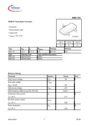
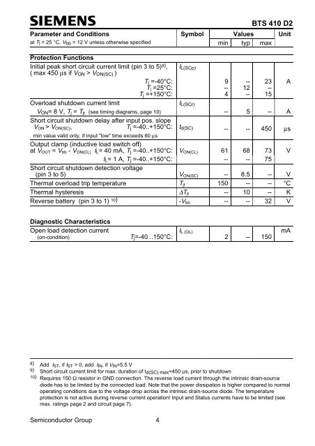
BTS 410 D2<br />
Parameter and Conditions Symbol Values Unit<br />
at Tj = 25 °C, V bb = 12 V unless otherwise specified min typ max<br />
Protection Functions<br />
Initial peak short circuit current limit (pin 3 to 5) 9) ,<br />
( max 450 µs if V ON > V ON(SC) )<br />
T j =-40°C:<br />
T j =25°C:<br />
T j =+150°C:<br />
Overload shutdown current limit<br />
I L(SCp)<br />
I L(SCr)<br />
9 -- 23<br />
-- 12 --<br />
4 -- 15<br />
V ON = 8 V, T j = T jt (see timing diagrams, page 10) -- 5 -- A<br />
Short circuit shutdown delay after input pos. slope<br />
V ON > V ON(SC) ,<br />
T j =-40..+150°C: t d(SC) -- -- 450 µs<br />
min value valid only, if input "low" time exceeds 60 µs<br />
Output clamp (inductive load switch off)<br />
at V OUT = V bb - V ON(CL) I L = 40 mA, T j =-40..+150°C: V ON(CL) 61 68 73 V<br />
I L = 1 A, T j =-40..+150°C: -- -- 75<br />
Short circuit shutdown detection voltage<br />
(pin 3 to 5) V ON(SC) -- 8.5 -- V<br />
Thermal overload trip temperature T jt 150 -- -- °C<br />
Thermal hysteresis ∆T jt -- 10 -- K<br />
Reverse battery (pin 3 to 1) 10) -V bb -- -- 32 V<br />
A<br />
Diagnostic Characteristics<br />
Open load detection current<br />
(on-condition)<br />
T j =-40 ..150°C:<br />
I L (OL)<br />
2 -- 150<br />
mA<br />
8) Add I ST , if I ST > 0, add I IN , if V IN >5.5 V<br />
9) Short circuit current limit for max. duration of t d(SC) max =450 µs, prior to shutdown<br />
10) Requires 150 Ω resistor in GND connection. The reverse load current through the intrinsic drain-source<br />
diode has to be limited by the connected load. Note that the power dissipation is higher compared to normal<br />
operating conditions due to the voltage drop across the intrinsic drain-source diode. The temperature<br />
protection is not active during reverse current operation! Input and Status currents have to be limited (see<br />
max. ratings page 2 and circuit page 7).<br />
Semiconductor Group 4