Installation Manual - Platt Electric Supply
Installation Manual - Platt Electric Supply
Installation Manual - Platt Electric Supply

You also want an ePaper? Increase the reach of your titles
YUMPU automatically turns print PDFs into web optimized ePapers that Google loves.
HAI Auxiliary Switch Overview<br />
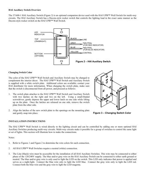
The 37A00-1 HAI Auxiliary Switch (Figure 2) is an optional companion device used with the HAI UPB Wall Switch for multi-way<br />
circuits. The HAI Auxiliary Switch has a Decora-style rocker switch that controls the lighting load in the exact same manner as the<br />
Decora-style rocker switch on the HAI UPB Wall Switch.<br />
LED<br />
INDICATOR<br />
TOP<br />
(ON/BRIGHT)<br />
BOTTOM<br />
(OFF/DIM)<br />
BLACK<br />
GRAY<br />
BLUE<br />
YELLOW<br />
LINE<br />
*NEUTRAL<br />
(FOR RED INDICATOR)<br />
*NEUTRAL<br />
(FOR BLUE INDICATOR)<br />
CONTROL<br />
Figure 2 – HAI Auxiliary Switch<br />
Changing Switch Color<br />
The color of the HAI UPB Wall Switch and Auxiliary Switch may be changed to<br />
complement the interior décor. The HAI UPB Wall Switch and Auxiliary Switch<br />
is supplied with a white switch plate. Additional colors are available; contact your<br />
HAI distributor for more information. When changing the switch plate, make sure<br />
that the switch is disconnected from all power, and proceed as follows:<br />
1. The switch plate attaches to the HAI UPB Wall Switch and Auxiliary Switch<br />
with two latches on the right and two on the left. Using a small-bladed<br />
screwdriver, gently depress the upper and lower latch on one side while lifting<br />
up on the plate. Once the latches are released on one side, remove the switch<br />
plate from the other side.<br />
2. Align the latches of the new switch plate to the openings on the mounting plate<br />
and gently snap into place.<br />
Figure 3 – Changing Switch Color<br />
INSTALLATION INSTRUCTIONS<br />
The HAI UPB Wall Switch is wired directly to the lighting circuit and can be controlled by adding one or more optional HAI<br />
Auxiliary Switches producing multi-way circuits. Multi-way circuits make it possible for a group of switches to control the same light<br />
or set of lights. This section will illustrate how to make the connections.<br />
Notes:<br />
1. Refer to Figures 1 and Figure 2 to determine the wire colors for each connection.<br />
2. All HAI UPB Wall Switches require a neutral (white) connection.<br />
3. The Line (black) wire must be accessible for the installation of all HAI Auxiliary Switches. This wire may be connected to either<br />
phase of the 120/240V supply. The blue and/or gray wire on the HAI Auxiliary Switch can be connected to either earth ground or<br />
neutral. The blue and/or gray wire is only used to light the LED on the switch. This LED only indicates that power is applied and<br />
serves as a night-light. Connect the blue wire only to light the LED blue. Connect the gray wire only to light the LED red.<br />
Connect both the blue wire and the gray wire to light the LED magenta.